DC-DC converter

Advert

DC-DC converter

Home Forums Electronics in the Workshop DC-DC converter

Viewing 23 posts - 51 through 73 (of 73 total)
  • Author
    Posts
  • #463447
    Neil Wyatt
    Moderator
      @neilwyatt
      Posted by Michael Gilligan on 07/04/2020 15:04:22:

      Hidden in plain sight, Joe

      The photo is grabbed from the link that you provided.

      MichaelG.

      What do you need 1.5V AAAs for?

      Alkaline AAAs drop to 1.2v about half way through their discharge life, NiMH AAA by about 15-20% (to 1.3V with low currents).

      If you only need low power for relatively short periods you could use NiMH ones and recharge frequently?

      Neil


      Edited By Neil Wyatt on 09/04/2020 13:05:45

      Advert
      #463449
      SillyOldDuffer
      Moderator
        @sillyoldduffer

        Found something interesting about my Lidl Caliper powered from a clean battery yesterday – it can interfere with itself.

        As the caliper only consumes 6 microamps, a 250kΩ load, I'd assumed a 9V battery and 10kΩ potentiometer would be stiff enough as a potential divider to power the caliper.

        Not so! The caliper outputs about 140mV of noise at the battery terminals. This sufficient to cause a poorly regulated supply to dip below critical voltage, causing misreadings.

        Using a 1kΩ potentiometer to divide 9V down to 1.55V is far more stable. With a 10kΩ pot the caliper fails at 1.48V, with a 1kΩ pot it worked down to 1.40V

        With the caliper operating correctly at normal full battery (1.55V), I injected noise into the supply. 9mV of external noise is enough to randomly toggle the minus sign. With 40mV of injected noise, the digits start flipping occasionally. At 90mV they flip continually.

        In short, the caliper is:

        • intolerant of low battery volts – the caliper stops working when its SR44 cell drops 0.15V from new.
        • sensitive to electrical noise on the supply, including it's own!

        Going to take it apart later. I expect to find no decoupling because the caliper normally relies on the battery to smooth out internal noise and eliminate external noise.

        Making calipers work with an external supply is probably quite simple – relatively low impedance volts (like my 1kΩ potential divider), plus a decoupling capacitor at the caliper terminals to get rid of any noise. A shielded or twisted cable decoupled at the power supply as well would be prudent.

        For a small fee I might measure how many volts are needed to kill the caliper. It took an accidental 1.9V without complaint. Fussier about too few volts than too many.

        Dave

        #463458
        Michael Gilligan
        Participant
          @michaelgilligan61133
          Posted by Neil Wyatt on 09/04/2020 13:04:17:

          Posted by Michael Gilligan on 07/04/2020 15:04:22:

          Hidden in plain sight, Joe

          The photo is grabbed from the link that you provided.

          MichaelG.

          What do you need 1.5V AAAs for?

          Alkaline AAAs drop to 1.2v about half way through their discharge life, NiMH AAA by about 15-20% (to 1.3V with low currents).

          If you only need low power for relatively short periods you could use NiMH ones and recharge frequently?

          Neil

          .

          I don’t, Neil

          Joe was picking-up on the exchange that I had with ndiy

          [ your examples nicely demonstrate my original point ]

          MichaelG.


          Edited By Michael Gilligan on 09/04/2020 14:12:01

          #463459
          Neil Wyatt
          Moderator
            @neilwyatt
            Posted by SillyOldDuffer on 09/04/2020 13:15:58:

            Found something interesting about my Lidl Caliper powered from a clean battery yesterday – it can interfere with itself.

            As the caliper only consumes 6 microamps, a 250kΩ load, I'd assumed a 9V battery and 10kΩ potentiometer would be stiff enough as a potential divider to power the caliper.

            Not so! The caliper outputs about 140mV of noise at the battery terminals. This sufficient to cause a poorly regulated supply to dip below critical voltage, causing misreadings.

            Using a 1kΩ potentiometer to divide 9V down to 1.55V is far more stable. With a 10kΩ pot the caliper fails at 1.48V, with a 1kΩ pot it worked down to 1.40V

            With the caliper operating correctly at normal full battery (1.55V), I injected noise into the supply. 9mV of external noise is enough to randomly toggle the minus sign. With 40mV of injected noise, the digits start flipping occasionally. At 90mV they flip continually.

            In short, the caliper is:

            • intolerant of low battery volts – the caliper stops working when its SR44 cell drops 0.15V from new.
            • sensitive to electrical noise on the supply, including it's own!

            Going to take it apart later. I expect to find no decoupling because the caliper normally relies on the battery to smooth out internal noise and eliminate external noise.

            Making calipers work with an external supply is probably quite simple – relatively low impedance volts (like my 1kΩ potential divider), plus a decoupling capacitor at the caliper terminals to get rid of any noise. A shielded or twisted cable decoupled at the power supply as well would be prudent.

            For a small fee I might measure how many volts are needed to kill the caliper. It took an accidental 1.9V without complaint. Fussier about too few volts than too many.

            Dave

            So add a capacitor to your 10K version to reduce the source impedance

            Neil

            #463503
            Macolm
            Participant
              @macolm

              It is only to be expected that the calliper IC will draw current spikes that translate to voltage noise. In a static state, CMOS logic draws only nano-amps. The operating current is due to charging and discharging internal capacitances on each clock edge. There needs to be adequate decoupling to limit the voltage excursion this causes. A battery may just be good enough, but a suitable capacitor should be better.

              In view of the very small margin below the battery voltage for the chip to work correctly, I again suggest investigating a slightly higher external supply, but still with adequate local decoupling at the battery terminals, or even better as near the power connections on the chip as possible.

              Do we know the clock frequency used? An electrolytic may not be best – a suitable ceramic is generally better at higher frequencies. The leads should be short to avoid adding stray inductance in series with the capacitor. A correctly designed surface mount capacitor fitment would be best, but it may be a bit late for that!

              F

              #463525
              John Baron
              Participant
                @johnbaron31275

                I haven't read the whole thread, but have you re-soldered the battery connections !

                I've got/had a couple where the display couldn't make up its mind and re-soldering the battery connections on the board cured the issue !

                #463529
                SillyOldDuffer
                Moderator
                  @sillyoldduffer
                  Posted by Neil Wyatt on 09/04/2020 14:10:25:

                  Posted by SillyOldDuffer on 09/04/2020 13:15:58:

                  Using a 1kΩ potentiometer to divide 9V down to 1.55V is far more stable. With a 10kΩ pot the caliper fails at 1.48V, with a 1kΩ pot it worked down to 1.40V

                  Making calipers work with an external supply is probably quite simple – relatively low impedance volts (like my 1kΩ potential divider), plus a decoupling capacitor at the caliper terminals to get rid of any noise.

                  So add a capacitor to your 10K version to reduce the source impedance

                  Neil

                  10uF from the pot wiper to ground didn't make any difference. It helps when placed across the battery contacts, the difference being eliminating the length of the leads.

                  Macolm makes a good point about finding the clock frequency – the spikes are caused by square waves and will have a substantial higher frequency component. If it's easy to do I'll identify the clock frequency and try various decoupling values.

                  The surprise to me is how critical about power this caliper is, but it's not a showstopper.

                  Dave

                  #463540
                  Anonymous

                    I'd be surprised if the clock frequency is more than a few kilohertz. The process isn't doing anything particularly fast or complicated so a high clock speed isn't needed. In CMOS circuits the dynamic power consumption is proportional to frequency and the supply voltage squared.

                    Think I'll stick to using mechanical micrometers – no batteries needed. I don't trust all this electronics nonsense.

                    Andrew

                    Edited By Andrew Johnston on 09/04/2020 19:05:15

                    #463574
                    Macolm
                    Participant
                      @macolm

                      I don’t have a feel for the core frequency. Certainly the data output is low kilohertz bit rate. However, the individual elements of the capacitive vernier can only be 10 or 20 pf. Secure motion tracking as well as accuracy might need a higher frequency, and of course, this could be the part that is upset by low supply voltage or interference.

                      Unfortunately, measurement is not particularly straightforward without specialised testgear.

                      F

                      #463583
                      Michael Gilligan
                      Participant
                        @michaelgilligan61133

                        Investigators may be interested to read Meyer’s patent for the capacitive system [now widely known as Chinese]

                        US4437055A

                        This, and his other patents are readily available [*] on espacenet: **LINK**

                        https://worldwide.espacenet.com/patent/

                        MichaelG.

                        .

                        [*] Just search for: "MEYER HANS ULRICH" [CH]

                        #463806
                        SillyOldDuffer
                        Moderator
                          @sillyoldduffer
                          Posted by Macolm on 09/04/2020 20:55:16:

                          I don’t have a feel for the core frequency. Certainly the data output is low kilohertz bit rate. However, the individual elements of the capacitive vernier can only be 10 or 20 pf. Secure motion tracking as well as accuracy might need a higher frequency, and of course, this could be the part that is upset by low supply voltage or interference.

                          Unfortunately, measurement is not particularly straightforward without specialised testgear.

                          F

                          So I opened it up and performed a post-mortem!

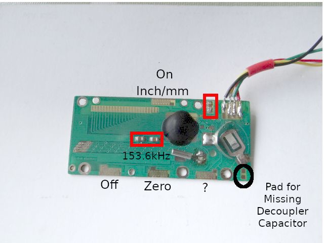
                          dsc06222_1.jpg

                          The photo shows the interesting top side of the circuit board. (On the other side is the slide movement detector, just a lot of parallel tracks.)

                          The toothy tracks on the edges are for the control buttons. There's an unused set marked ?, don't know what the missing button is for.

                          The silver tube clock crystal runs at 153.6kHz which is low radio frequency. (BBC R4 Long Wave is on 198kHz) No idea why 153.6kHz, which seems an odd number? Maybe Michael's link to the patent explains!

                          Anyway there are only 3 passive SMD components in the whole shebang, shown ringed in red. In the bottom right hand corner are pads for another, missing, SMD component, ringed in black. The pads connect across the supply rail and are certainly intended to take a decoupling capacitor.

                          This digital caliper was made by a bunch of cheapskates! I expected more for £4.99, including VAT.

                          Dave

                          #463810
                          Michael Gilligan
                          Participant
                            @michaelgilligan61133

                            Posted by SillyOldDuffer on 10/04/2020 18:57:08:
                            […]

                            The silver tube clock crystal runs at 153.6kHz which is low radio frequency. (BBC R4 Long Wave is on 198kHz) No idea why 153.6kHz, which seems an odd number? Maybe Michael's link to the patent explains!

                            […]

                            I have a vague recollection that 2048 comes into the scaling of these things

                            153600/2048 = 75

                            Which may, or may not, be relevant to something dont know

                            MichaelG.

                            .

                            P.S. __ I have mentioned this before, but it may be worth linking here:

                            http://www.pcbheaven.com/exppages/Digital_Caliper_Protocol/

                            At 2 March 2012, 10:30:16 user Hans U. Meyer wrote:

                            Edited By Michael Gilligan on 10/04/2020 19:32:26

                            #463813
                            Anonymous

                              Bit higher that I expected, but almost certainly related to comms or LCD data rate. Incidentally:

                              3 x 512 = 1536

                              so definitely powers of 2 come into it.

                              SoD: Your task for tomorrow is to stick the 'scope on the comms and see what the bit rate looks like. smile

                              Andrew

                              #463975
                              SillyOldDuffer
                              Moderator
                                @sillyoldduffer
                                Posted by Andrew Johnston on 10/04/2020 19:22:56:

                                Bit higher that I expected, but almost certainly related to comms or LCD data rate. Incidentally:

                                3 x 512 = 1536

                                so definitely powers of 2 come into it.

                                SoD: Your task for tomorrow is to stick the 'scope on the comms and see what the bit rate looks like. smile

                                Andrew

                                Andrew's wish is my command!

                                Hard to see what the LCD feeds do when the slide is moved because there's no way of getting a probe on the LCD lines after the caliper has been reassembled.

                                However, the two of the 4 wires I soldered on to the caliper are data for an external display. On these the minimum pulse width is 80uS, and the caliper signals in 1.23kHz bursts.

                                I don't know if this output and the LCD update together at the same rate. These things aren't meant to come apart and in my clunky hands the LCD has stopped working! I've also lost one of the buttons.

                                blush

                                Dave

                                #463988
                                Paul H 1
                                Participant
                                  @paulh1

                                  Dave (SOD), I've been following your experiments with great interest. Regarding the LCD, from the PCB photo it looks like the LCD has a zebra strip that presses against the PCB. Having an appliance I have been trying to debug/repair for several months with one of the same style of connections, it only takes a slight misalignment for the contacts to be in the wrong place, so perhaps a bit of fiddling around with the alignment and pressure would help.

                                  Are you going to try a decoupling cap on the position you have shown?

                                  Paul

                                  #463993
                                  SillyOldDuffer
                                  Moderator
                                    @sillyoldduffer
                                    Posted by Paul H 1 on 11/04/2020 14:12:41:

                                    it only takes a slight misalignment for the contacts to be in the wrong place, so perhaps a bit of fiddling around with the alignment and pressure would help.

                                    Are you going to try a decoupling cap on the position you have shown?

                                    Paul

                                    Hi Paul,

                                    I think you're right – the contacts between LCD panel and board are via a sort of rubber strip thingy, which fell off! Very likely I put it back out of alignment. Also, one of the screws has gouged through the board and it's not applying pressure to the strip at one end. Fortunately, I'm experimenting with a cheap caliper I dropped on a concrete floor and then stood on, not a brand-new Mitutoyo!

                                    I intended to try decoupling but I can't test it now I've broken the display. Why is nothing is ever easy?

                                    sad

                                    Dave

                                    #464005
                                    Michael Gilligan
                                    Participant
                                      @michaelgilligan61133
                                      Posted by SillyOldDuffer on 11/04/2020 14:43:45:

                                      Hi Paul,

                                      I think you're right – the contacts between LCD panel and board are via a sort of rubber strip thingy, which fell off!

                                      .

                                      ferinstance : **LINK**

                                      https://www.c-a-d.com.hk/design.htm

                                      MichaelG.

                                      #464011
                                      Neil Wyatt
                                      Moderator
                                        @neilwyatt

                                        Posted by SillyOldDuffer on 11/04/2020 14:43:45:

                                        the contacts between LCD panel and board are via a sort of rubber strip thingy, which fell off! Very likely I put it back out of alignment.

                                        'Zebra strip' (some are black and white) with alternating conductive and non-conductive stripes. The spacing should be cleverly designed so that you don't need the strip perfectly aligned, just the PCB and the display unit lined up with each other.

                                        Usually the problems are either tiny bits of grit breaking a contact or finger grease. Degrease in alcohol (meths works OK).

                                        Neil

                                        #464025
                                        Anonymous
                                          Posted by SillyOldDuffer on 11/04/2020 13:17:01:
                                          These things aren't meant to come apart and in my clunky hands the LCD has stopped working!

                                          It happens to us all. I knocked a cup of coffee over my keyboard this morning and I'm only just back up and running. Although to be fair in the meantime I've also had lunch, gone for an 8 mile cycle ride and had a long sulk sitting out in the garden.

                                          SoD has it nailed! Some playing with the numbers gives:

                                          153600/128 = 1200

                                          or 1200 baud for the serial comms. The measured value of 1.23kHz is pretty close allowing for measurement error and tiddly crystals that aren't that accurate.

                                          I hate zebra strips. Many years ago in the mad world of motor racing the company I worked for used them to connect the electronics to the graphics LCD display on a handheld unit. The build instructions consisted of assembling the unit, seeing if the LCD worked and if not dis-assembling and repeating until it did. Mind you the draughtsman/mechanical 'designer' was incompetent and got the heave ho shortly afterwards.

                                          Andrew

                                          #464038
                                          SillyOldDuffer
                                          Moderator
                                            @sillyoldduffer
                                            Posted by Andrew Johnston on 11/04/2020 17:09:56:

                                            Posted by SillyOldDuffer on 11/04/2020 13:17:01:
                                             
                                            These things aren't meant to come apart and in my clunky hands the LCD has stopped working!

                                            It happens to us all. …

                                            SoD has it nailed! Some playing with the numbers gives:

                                            153600/128 = 1200

                                            or 1200 baud for the serial comms. The measured value of 1.23kHz is pretty close allowing for measurement error and tiddly crystals that aren't that accurate.

                                            I hate zebra strips. …

                                            Andrew

                                            Some of us are more accident prone than others! Intending to follow Neil's advice, I took her apart again and discovered someone who cannot be named (it was the perpendicular pronoun), had put the strip on the insulated side of the LCD.

                                            1200 baud is convincing, I hadn't twigged that relationship!

                                            Another noise relevant observation. Running the caliper directly off a 1.5V Zinc Chloride 'C' battery and short leads, the self-generated noise falls to about 40mV max. (Distinctly better than running it off a 9V battery and potential divider.) So far so good, but touching the metal slide with my hand caused the noise to double. Turns out the caliper's metalwork is connected to battery positive. Normally this wouldn't matter, but it's likely to introduce noise if the remote battery or power supply is on the end of a long lead.

                                            There's a magic smoke implication too. If a mains DC power supply is used to run a positive frame caliper touching an earthed machine, make sure the mains PSU isn't DC negative earthed, as many metal boxed units are. (This is DC fuse blowing problem rather than a mains shock hazard.) Wall warts should be OK, unless someone knows they ever have a DC line connected to mains earth? I assume their DC outputs always float?

                                            Dave


                                            Edited By SillyOldDuffer on 11/04/2020 17:55:37

                                            #464042
                                            Neil Wyatt
                                            Moderator
                                              @neilwyatt

                                              To be fair it's the only practical solution if the display has the contacts on the glass.

                                              #464084
                                              Meunier
                                              Participant
                                                @meunier
                                                Posted by Andrew Johnston on 11/04/2020 17:09:56:

                                                Posted by SillyOldDuffer on 11/04/2020 13:17:01:
                                                These things aren't meant to come apart and in my clunky hands the LCD has stopped working!

                                                snip/

                                                SoD has it nailed! Some playing with the numbers gives:

                                                153600/128 = 1200

                                                or 1200 baud for the serial comms. /snip

                                                That's a magic number in comms. The first modem we received from the US in 1964 was 2400 baud.
                                                Made by ITT and built like the proverbial, about 18ins x 12 x 18 with the individual plug-in modules enclosed in square alu frames and edge-connectors down.
                                                Later came 4800/1200/300/150/75 baud modems.
                                                The 1200 baud modems went to Paris and the PTT had to type-approve them and stuck engraved brass labels on each one. (he's rambling again…)
                                                DaveD

                                                #467666
                                                Michael Gilligan
                                                Participant
                                                  @michaelgilligan61133
                                                  Posted by SillyOldDuffer on 30/03/2020 17:31:11:

                                                  Here's my contribution.

                                                  I have a Lidl Digital Caliper to which I've added remote wiring. […]

                                                  My caliper fails absolutely below 1.48V and was reliable only above 1.51V. The SR44 cell produces 1.55V, and this voltage appears to be critical : a drop of 0.05V is enough to upset this caliper, at least with my noisy supply. I took it up to 1.65V with no ill-effects.

                                                  This caliper draws a constant 6 micro-amps whether on or off, or switching between mm and inches. It doesn't draw more current when the slide is moved, but pressing the Zero button takes 15 micro-amps.

                                                  Real batteries: Duracell Plus Power AAA and Energizer AA both nominally 1.5V but actually 1.64V out of the packet. Just changed the Duracells in my TV remote, they're down to 1.08V.

                                                  Conclusions.

                                                  The caliper is VERY sensitive to low voltages AND it dislikes noise.

                                                  […]

                                                  .
                                                  Just reviving this thread to add a note which may be useful

                                                  My Mitutoyo caliper was still working fine, but displaying B for battery warning

                                                  Installed a new Energiser 357 [SR44] and checked the voltage of the old one: 1.37V

                                                  MichaelG.

                                                Viewing 23 posts - 51 through 73 (of 73 total)
                                                • Please log in to reply to this topic. Registering is free and easy using the links on the menu at the top of this page.

                                                Advert

                                                Latest Replies

                                                Viewing 25 topics - 1 through 25 (of 25 total)
                                                Viewing 25 topics - 1 through 25 (of 25 total)

                                                View full reply list.

                                                Advert

                                                Newsletter Sign-up