crompton motor and dewhurst switch problems

Advert

crompton motor and dewhurst switch problems

Home Forums Beginners questions crompton motor and dewhurst switch problems

Viewing 7 posts - 1 through 7 (of 7 total)
  • Author
    Posts
  • #133469
    mike smith 5
    Participant
      @mikesmith5

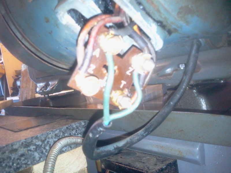
      I've got the wiring diagram for the Dewhurst switch to the Crompton motor , I have followed the diagram and this is how it is wired.This is where the problems start ; in forward the motor runs rough and not up to speed,in reverse it trips the power.I had the motor off a friend, he had never bothered with reverse and it was wired up diect to a NVR switch and runs sweet in forward and up to speed. That was connected to AZ and A.ft82tydhfd1e2mc_large.jpgI think the problem is that the wires in the motor connection block have been moved about because there are no jumpers to make it run direct from a plug, here is a photo of the motor connection block2013-10-23 12.16.23.jpg

      wires coming out of the motor housing to the connection block are as follows; 2 red to AZ

      red and black to T

      black to A

      black to Z

      capacitor to A and Z

      hope you can help as i'm pulling my hair out

      many thanks, mike


      Edited By JasonB on 23/10/2013 18:29:15

      Advert
      #6924
      mike smith 5
      Participant
        @mikesmith5
        #801526
        petejchadwick@gmail.com
        Participant
          @petejchadwickgmail-com

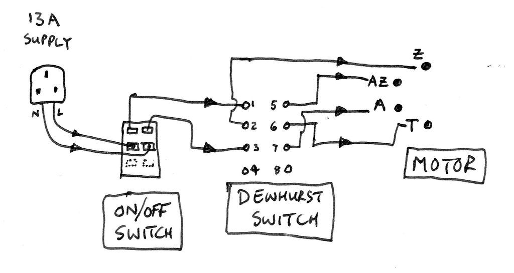
          Hi folks, I digitised a similar design for my own use today with my Myford Super 7 and thought others might benefit from having a copy themselves. Feel free to print out.

          NOTE – A safety switch is highly advised between the AC supply and the Dewhurst switch. And depending on how you are mounting the switch and to what surface, it may well be worth adding an additional ground point as illustrated, too many grounds can never really hurt.

          Crompton & Dewhurst Switch Diagram_20250605_232809_0000


          #802488
          Howard Lewis
          Participant
            @howardlewis46836

            Sounds as if the wiring ton the Start windings and Run windings might have been reversed

            The Start windings are fed through a centrifugal switch on the end of the motor. As the motor speeds up, the Start windings are disconnected. (You may hear a clock a click as the motor slows down after being switched off.

            Dewhurst switches do mot like being used as ON/OFF switches, and the arcing will burn the contacts. Better to have an ON/OFF switch, or an NVR switch between the mains supply and the Dewhurst.

            DEWHURST SWITCH WIRING

            #802523
            Michael Gilligan
            Participant
              @michaelgilligan61133
              On petejchadwick@gmail.com Said:

              Hi folks, I digitised a similar design for my own use today with my Myford Super 7 and thought others might benefit from having a copy themselves. […]

              Very tidily done, Peter

              Thank You

              MichaelG.

              #802527
              not done it yet
              Participant
                @notdoneityet

                Mike, as a beginner a few points which may improve your chances of a successful outcome.

                The most common Dewhurst switch is only sufficiently robust for relatively low powered motors.

                Only change the motor direction with the motor power turned off.  Otherwise it will likely fail in a short time scale.

                Is this fresh motor of an appropriate size -both power-wise and speed?

                #802543
                noel shelley
                Participant
                  @noelshelley55608

                  Petes drawing is excellent but ONLY if no one has messed with the wires to the terminal block. From the terminal block it seems it MAY have a thermal cutout. A single cap indicates that it is cap start, induction run. A copy of Tubal Cains book The Model Engineers Hand book has a good section on motors including wiring diagrams that will answer your questions. Old convention was red and black = run windings and yellow and blue = start windings. Good luck, Noel

                Viewing 7 posts - 1 through 7 (of 7 total)
                • Please log in to reply to this topic. Registering is free and easy using the links on the menu at the top of this page.

                Advert

                Latest Replies

                Home Forums Beginners questions Topics

                Viewing 25 topics - 1 through 25 (of 25 total)
                Viewing 25 topics - 1 through 25 (of 25 total)

                View full reply list.

                Advert

                Newsletter Sign-up