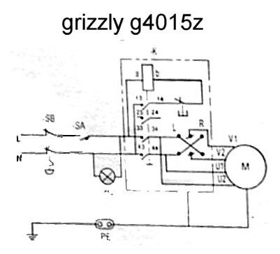
Clarke CL 500 switch
Clarke CL 500 switch
- This topic has 7 replies, 5 voices, and was last updated 23 June 2018 at 17:15 by
roger mason 2.
Viewing 8 posts - 1 through 8 (of 8 total)
Viewing 8 posts - 1 through 8 (of 8 total)
- Please log in to reply to this topic. Registering is free and easy using the links on the menu at the top of this page.
Latest Replies
Viewing 25 topics - 1 through 25 (of 25 total)
-
- Topic
- Voices
- Last Post
Viewing 25 topics - 1 through 25 (of 25 total)
Latest Issue
Newsletter Sign-up
Latest Replies
- 30w low voltage PWM controller
- Chester hobby store gift vouchers
- VFD Article in May issue 351
- Stuart No.1 on a Myford Super-7??
- Magnetic bases – stored on or off?
- Sieg C1 lathe autofeed and screw cutting
- Drilling Holes In Aluminium Tube
- Drilling 316 Stainless Steel
- What Did You Do Today 2025
- Boxford Cud or ML7


