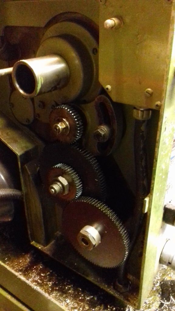
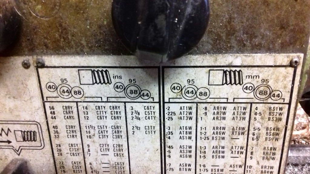
Changewheel conundrum
Changewheel conundrum
- This topic has 28 replies, 14 voices, and was last updated 17 November 2018 at 08:22 by
 Brian Wood.


- Please log in to reply to this topic. Registering is free and easy using the links on the menu at the top of this page.
Latest Replies
-
- Topic
- Voices
- Last Post
-
-
A4 stainless
Started by:
David Ambrose
in: Materials
- 11
-
23 August 2025 at 20:05
Martin Kyte
-
Phone Phreaking
Started by:
Michael Gilligan
in: Clocks and Scientific Instruments
- 11
-
23 August 2025 at 20:04
Marcus Bowman
-
Blackgates 3 Way Toolpost Casting
Started by:
John McCulla
in: Materials
- 11
-
23 August 2025 at 19:28
Clive Foster
-
QCTP for chester lathe
Started by:
Chris12
in: Beginners questions
- 11
-
23 August 2025 at 17:36
dk0
-
This weeks oddity!
Started by:
Martin King 2
in: Help and Assistance! (Offered or Wanted)
- 4
-
23 August 2025 at 17:29
Martin King 2
-
Asong power feed?
Started by:
Hollowpoint
in: General Questions
- 5
-
23 August 2025 at 16:55
Stuart Smith 5
-
New member, progress no.1 rest
Started by:
flyingsailor
in: Introduce Yourself – New members start here!
- 5
-
23 August 2025 at 16:11
flyingsailor
-
My week this week! My workshop videos
1
2
…
11
12
Started by:
Phil Whitley
in: The Tea Room
- 16
-
23 August 2025 at 16:05
Phil Whitley
-
Material advice
Started by:
tobyonekenobi
in: Materials
- 9
-
23 August 2025 at 11:19
Martin Connelly
-
Yet another scam
Started by:
Dell
in: The Tea Room
- 9
-
23 August 2025 at 11:08
Howard Lewis
-
Taylor Hobson cutter grinder modificaton
1
2
Started by:
David George 1
in: Workshop Tools and Tooling
- 9
-
23 August 2025 at 08:43
Andrew Crow
-
Museum donation
Started by:
Stephen Wessel 1
in: Introduce Yourself – New members start here!
- 2
-
22 August 2025 at 20:36
Bazyle
-
Casting – off center hole correction
Started by:
colin hamilton
in: Workshop Techniques
- 9
-
22 August 2025 at 17:38
colin hamilton
-
Granville lathe leadscrew change wheel
Started by:
JACK SIDEBOTHAM
in: Help and Assistance! (Offered or Wanted)
- 10
-
22 August 2025 at 17:07
Howard Lewis
-
wood working
Started by:
Danni Burns
in: Beginners questions
- 9
-
22 August 2025 at 15:55
Danni Burns
-
3″ Castings – Help/Advice needed
Started by:
Andy Porter 1
in: Traction engines
- 4
-
22 August 2025 at 13:15
JasonB
-
AI ads
Started by:
Ian Parkin
in: The Tea Room
- 5
-
22 August 2025 at 13:00
jimmy b
-
1″ Minnie Traction Engine
Started by:
milburyring@btinternet.com
in: Traction engines
- 3
-
22 August 2025 at 08:53
milburyring@btinternet.com
-
Solar panel
Started by:
duncan webster 1
in: Electronics in the Workshop
- 8
-
22 August 2025 at 07:19
Michael Gilligan
-
The stand alone weight for tower clock
1
2
Started by:
dk0
in: Clocks and Scientific Instruments
- 12
-
21 August 2025 at 23:59
Clive Steer
-
Install & commission of a Chester Cub 630 (Warco GH750)
1
2
3
Started by:
Calum
in: Manual machine tools
- 22
-
21 August 2025 at 21:52
noel shelley
-
Softening epoxy
Started by:
John Haine
in: General Questions
- 17
-
21 August 2025 at 18:57
Martin Dilly 2
-
What Did You Do Today 2025
1
2
…
9
10
Started by:
JasonB
in: The Tea Room
- 35
-
21 August 2025 at 17:38
Dalboy
-
Denford Orac refit
Started by:
Richard Evans 2
in: CNC machines, Home builds, Conversions, ELS, automation, software, etc tools
- 3
-
21 August 2025 at 14:56
Richard Evans 2
-
F360 stock from solid
Started by:
Roderick Jenkins
in: CNC machines, Home builds, Conversions, ELS, automation, software, etc tools
- 9
-
21 August 2025 at 10:44
Roderick Jenkins
-
A4 stainless


