Cable Gland

Advert

Cable Gland

Home Forums Electronics in the Workshop Cable Gland

Viewing 21 posts - 51 through 71 (of 71 total)
  • Author
    Posts
  • #454110
    Emgee
    Participant
      @emgee

      Clive

      Check the documentation that came with the starter for details of any test buttons.

      Emgee

      Advert
      #454112
      Johnboy25
      Participant
        @johnboy25

        2b1d0d45-a004-42d5-9c43-1e06a11d2f1e.jpeg

        #454113
        Clive B 1
        Participant
          @cliveb1

          Bill

          Yes, I know what you mean about mini trunking I’ve used it myself in the past, glued, nailed, screwed whatever it takes to get it to hold, I don’t think it will be glued not with all that shaking going on.

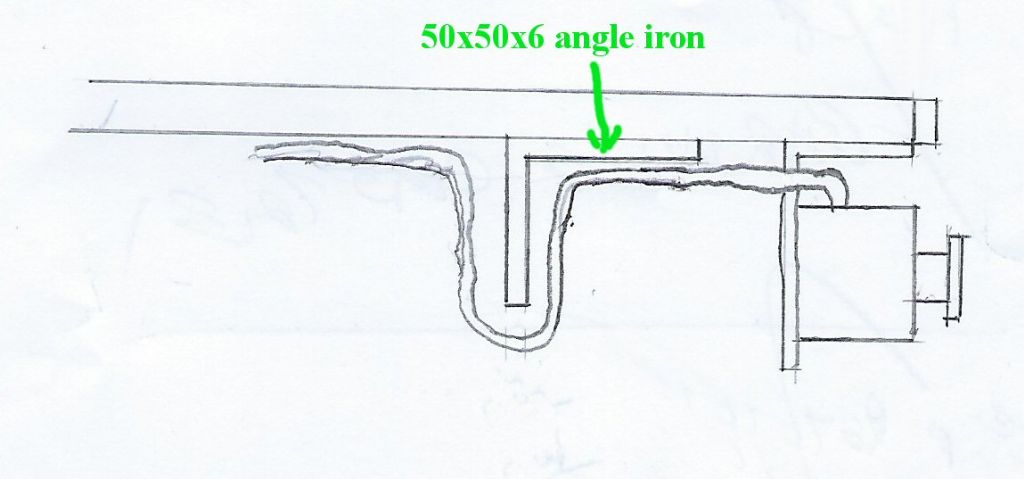
          At the end of the day I suppose it comes down to whatever is desirable, I must admit I was going to settle for just clipping the wire and because such a big hole needs to be drilled to accommodate glands, I was going to just loop the cable under the angle iron.

          But since you’ve mentioned mini trunking I’m now debating whether to use that and do as someone else suggested cut a grommet into two pieces and glue them into the hole both sides of the angle.

          Clive

          under angle iron.jpg

          #454114
          Johnboy25
          Participant
            @johnboy25

            Photo Sorted. 👍

            the cabling to the E-stop would better in two core flex. 3182Y if you haven’t got two core standard 3 core 3183Y and ignore the green/yellow earth.

            john

            Edited By Johnboy25 on 24/02/2020 22:16:33

            #454119
            Clive B 1
            Participant
              @cliveb1

              Emgee

              I don’t have any documentation; I suppose I could Google Moeller MSE-M240V and see if that turns something up.

              Not to worry though as long as it works that’s fine by me.

              Clive

              #454120
              Emgee
              Participant
                @emgee
                Posted by Clive B 1 on 24/02/2020 21:40:32:

                Emgee

                Thanks for clarifying the cable connections for me.

                I may as well find out, Looking at the DOL picture Iv'e already posted, am I right in assuming the little square test button is so the overload coil can be tested periodically much the same as an mcb in a consumer unit is tested.

                I can also see a small blue reset switch, is that to reset it after the test button has been pressed or indeed to reset it should the overload coil be activated at any time?

                Clive

                The sq Red Test button is operated by the cover mounted stop switch, the top Test plate is operated by the cover start button, you can of course use them with the cover removed if the power is on, you will then be working live so take care,
                The blue piece with cross slots is to set the overload to reset manually or automatically after an overload condition, suggest this is set to M so you have to press the stop button to reset the overload trip.

                Emgee

                #454124
                Clive B 1
                Participant
                  @cliveb1

                  Emgee

                  Would you be good enough to take a look at the photo Jonboy as modified and confirm it’s as the sketch below:

                  You will see I've removed the incorrect green wire.

                  I guess I just want to be sure we are all singing from the same hymn sheet.

                  Thanks for explaining about reset button, how stupid of me of course the buttons on the outer cover have got to press against something or I'd be pressing them forever.

                  dol switch wiring 3.jpg

                  #454133
                  Ian P
                  Participant
                    @ianp

                    Its late and was just going to turn my PC off when I saw the lasts posts on this thread. The thought then came to me that most of the topic has been about emergency stops.

                    I know these are so the motor can be stopped from any side of the machine but I then wondered how the machine can be started from any side of the machine?

                    If these are purely 'emergency' stop buttons then how is the motor started and stopped in normal use?

                    The original machine has an on/off switch on the motor its itself, it looks like a simple mechanical switch so presumably you intend to leave it permanently in the ON position and control the motor from your DOL mounted on the wall. Does this mean that you might have to walk round to the other side of the machine after you have started the motor?

                    Sometimes (and I'm guilty of this too) its possible to get carried away on a particular route to solving a problem without really analysing what the problem is. In this case the more switches, wiring, terminals, circuitry and other components that seem to be increasingly involved, the more likely that faults and operational complications will be possible.

                    The keep it simple approach has a lot in its favour, why not have a length of string strung just overhead that pulls out the 13A plug (like the communication cord in a train carriage). OK thats crude and its not really a serious suggestion but the proposed system of emergency stop switches carrying mains voltage does seem a good idea either.

                    What one does in their own home workshop does not have to be to industrial standards (its for your own use and its not operating 24 hours a day) but where possible it should at least be based on sound practice.

                    Rantover

                    Ian P

                    #454157
                    Johnboy25
                    Participant
                      @johnboy25

                      Clive…

                      that’s fine – your diagram concurs with what I was trying to describe.👍

                      John

                      #454165
                      Emgee
                      Participant
                        @emgee

                        Clive

                        You need to look at the electrical schematic shown on the earlier picture of the inside of the starter cover and compare the hand sketches with connections shown in the schematic. Follow the wiring format shown in the schematic.

                        There is no connection to A1 in the hand sketches, this is the live for the coil so the contactor will not function.

                        Emgee

                        #454221
                        Clive B 1
                        Participant
                          @cliveb1

                          Ian P

                          When I purchased the machine from new all it ever had was the no volt switch on top of the motor.

                          The cable came out from the side of the switch box and had a three pin plug on the end of it. Because I did not want to drape the cable over the top of the machines for obvious reasons, it was passed down through the same hole the chip extraction hose goes through and from there was plugged into a convenient socket outlet on the wall.

                          To turn the machine on or off was a case of having to reach over to do so, as matter of fact sometimes when I wanted to switch the machine off, I’d use a piece of wood save stretching over.

                          My plan now was to fit emergency stops and bring all the wiring from them into the switch box on top of the motor, doing away with the original switch altogether and putting a steel blanking plate on top of box.

                          The cabling would then come out of the side of the switch box including the power supply for the motor down through the hole in the table and the DOL would be fastened to a board and either hung on the side of the machine I’m working on or on the wall and from there a short cable with a three pin plug would be pushed into a convenient power point.

                          I’d love to be able to fix the DOL starter in one permanent position but because the whole machine has to be moved around due to space limitations, I can’t do that. ie if the machine was pushed against the wall the DOL was permanently fixed to I’d never be able to reach it.

                          Ian I dare say a lot of the guys on this forum have metal turning lathes or mills, a woodwork machine such as mine needs a lot of space, think about it, if I have a piece of wood to be planed and say its 8 foot long the machine will need at least 18 feet, 8 foot going in and 8 foot coming out plus enough space to feed it in and get it out of the machine so that’s why sometimes the machine is shoved up against a wall.

                          Believe me I am trying to persuade my wife we need to move, I am working on it laugh.

                          As you can see I’ve never had E/stop buttons on the machine, I was thinking I could use them to turn the machine off without the need to turn off at the DOL, having said that I don’t even know if this would have any adverse effect on the DOL or indeed if an E/stop has been operated I’d have to take the cover off the DOL and reset anything I’m hoping not.

                          Thank you for your comments they are much appreciated .

                          Clive

                          #454239
                          Clive B 1
                          Participant
                            @cliveb1

                            Emgee

                            I have to admit the cables as shown in my schematic sketch were copied as a result of someone connecting the starter to the motor and actually had it running.

                            You will see the incoming live is connected to terminal 1 L1 and not A1, having said that I really do appreciate what you are saying about the schematic diagram inside the cover, so heaven knows how it ran and switched off.

                            #454243
                            Ian P
                            Participant
                              @ianp

                              I fully understand the workspace envelope required for woodworking and when I need to use my radial arm saw now only do so when I can wheel it outside. I'm not sure though whether your current plan is going to be as convenient to operate as you expect.

                              In normal parlance, 'Emergency Stop' switches are just for that purpose. Using four separate ones just to stop the machine without having an equally easy to operate 'On' switch is highly unusual (or at least I have never come across a setup like that).

                              Some general thoughts (on this particular) machine control.

                              Feeding the motor through a contactor (as you are planning) then gives the No-Volt release feature that nowadays seems to be mandatory so that good.

                              The contactor should have a low voltage coil so that all the control wiring (some of which we now know needs to be flexible and frequently moved) is isolated and would not cause a hazard if it got damaged, tripped over, fell iunto a bucket of water, or whatever.

                              Only three low voltage wires (which would not need an earth) are needed to connect to two pushbuttons that would be the On/Off controls for the motor. If the Stop button is the larger or more prominent button of the pair, then in effect it is your E-Stop. You can have as many two button pairs as you want from the same three wires if you want to control the motor from several locations.

                              The more switches and controls you have, especially if they are widely dispersed the less likely one would be to instinctively know which one to use in a genuine emergency.

                              If this machine has approximately a 'square' format like a large table, then just two E-Stop switches or control positions on diagonally opposite corners are just as reachable as your four will be.

                              Other options to consider could be, a keyfob type wireless control of the motor maybe on your hand or wrist whilst working, foot operated switches (that need to be kept depressed).

                              Ian P

                              #454244
                              Johnboy25
                              Participant
                                @johnboy25

                                On some of the overload relays/trips the red button can be configured to auto reset or manual reset. I can’t remember if your type of DOL has this but if your using this to stop the machine there won’t be be a problem with having to manually resting the trip or by using any of the E-Stops (hope that makes sense 😳

                                Good point Emgee regarding the control coil A1 connection – it may be connected – it needs to be checked so that the contactor does ‘holds in’ when starting.

                                John

                                P.S.. Looking at the photo I think the red needs to be linked across NO to A1 that comes from the push button. So that the coil holds in once your finger is removed from the on button. 
                                Disclaimer: I can see the top of the connector block. 😳

                                Edited By Johnboy25 on 25/02/2020 15:05:12

                                #454255
                                Clive B 1
                                Participant
                                  @cliveb1

                                  Johnboy

                                  " Good point Emgee regarding the control coil A1 connection – it may be connected – it needs to be checked so that the contactor does ‘holds in’ when starting".

                                  I have to admit I haven't got a clue how to test it.

                                  Thanks again

                                  Clive

                                  #454256
                                  Clive B 1
                                  Participant
                                    @cliveb1

                                    Guys

                                    Could the coil A1 be already connected internally, all I know is the motor ran and switched off with it wired as shown on my sketch.

                                    I’ve got so much doubt in my mind I think I’m going to bring the E/stop cables into the old original switch box on top of the motor and because I’m way, way out of my depth and at this stage in the game I’ll get a qualified electrician in to do all the connections, including connecting up to the DOL starter.

                                    Needless to say, I will certainly make a sketch and photograph how it’s been done and if anyone’s interested, I can post it on the forum.

                                    I hope none of you have developed too much cramp in your fingers from all the typing youv'e done in replying to me laugh, and thank you all once again for your views and help. It’s been very much appreciated.

                                    Clive

                                    #454259
                                    Johnboy25
                                    Participant
                                      @johnboy25

                                      Clive if it’s ran before and you can switch of either by the stop or E-stop – you must be pretty close to finishing it.👍Don’t give just yet! I don’t know how far you are away from me but if your local-ish I’d happy to pop over to check it out. If not you could PM me with a short video?

                                      John

                                      p.s. If you don’t ask you won’t learn by your endeavours


                                      Edited By Johnboy25 on 25/02/2020 16:02:26

                                      #454287
                                      Clive B 1
                                      Participant
                                        @cliveb1

                                        John

                                        Thank you for your kind offer of popping over, sods law I'm in Stafford light years away from you.

                                        No doublt I'll be charged an arm and a leg for the job, but I don't want to get a belt off something even though the whole of the house wiring is RCD and RBCO protected.

                                        Thanks again

                                        Clive

                                        #454295
                                        Clive B 1
                                        Participant
                                          @cliveb1

                                          Ian P

                                          Sorry I must have missed your last posting, but having read it as I’ve already said this is getting way over my head, foot switches, key fobs plus all the cost of it.

                                          I’m retired and sadly don’t have the Duchy of Cornwall or Lancaster to finance me, pity laugh.


                                          I suppose at the end of the day that’s why I’d thought I’d have a crack at doing it myself, all I can say is at the moment I’ve got a machine I can’t use, maybe I should have stuck to reaching over to turn it on and off.

                                          Indecently I’ve got a compound sliding mitre saw much the same as yourself I can only use it if it’s not raining.

                                          Its big, the depth of cut 111mm and width of cut 343mm, thank heaven I don’t need to wire a DOL or emergency stop button to it.laugh

                                          It looks as though I will have to start trawling the net for my local sparks laugh

                                          Thank you for taking the time to try and help me


                                          Clive

                                          Edited By Clive B 1 on 25/02/2020 19:06:44

                                          Edited By Clive B 1 on 25/02/2020 19:08:01

                                          #454420
                                          Brian Morehen
                                          Participant
                                            @brianmorehen85290

                                            Your push to stop buttons I hope they all have a reset control otherwise once you release when operated the machine will restart , This is not what you require as a Emergancy stop or push to stop is just that Machined stopped. . Supply to Machine Starter control relay coil has been broken , Machine will not start untill the problem or reason has been been corrected.

                                            I solved this problem on my saw bench by fitting 2 way switching on each side of the bench.

                                            Your question on earthing asumeing the complete machine is metal everything will bond through the metalwork.

                                            Brian Morehen

                                            #454425
                                            Former Member
                                            Participant
                                              @formermember19781

                                              [This posting has been removed]

                                            Viewing 21 posts - 51 through 71 (of 71 total)
                                            • Please log in to reply to this topic. Registering is free and easy using the links on the menu at the top of this page.

                                            Advert

                                            Latest Replies

                                            Viewing 25 topics - 1 through 25 (of 25 total)
                                            Viewing 25 topics - 1 through 25 (of 25 total)

                                            View full reply list.

                                            Advert

                                            Newsletter Sign-up