Building a lathe stand ?

Advert

Building a lathe stand ?

Home Forums Manual machine tools Building a lathe stand ?

Viewing 14 posts - 1 through 14 (of 14 total)
  • Author
    Posts
  • #607158
    Rich2502
    Participant
      @rich2502

      Is this a good method of building a lathe stand?

      The rigid beam takes the load and everything else is independent of that, could be heavy timber construction. Once the beam is fabricated it could be skimmed on a mill both ends where the lathe feet touch down.

      My lathe would require a 1200 x 185 mm box section or channel.

      Advert
      #14623
      Rich2502
      Participant
        @rich2502
        #607165
        Nicholas Farr
        Participant
          @nicholasfarr14254

          Hi Rich2602, if you wish to use a hollow section or a channel, rather than just mill where the the feet go, it would be better to weld on four squares or two strips of say 6mm thick plate where the feet go and then mill the plates, that way you won't be milling a hollow into, or the reducing the thickness of your beam, two strips would only need a U shape weld around each end.

          Regards Nick.

          #607186
          duncan webster 1
          Participant
            @duncanwebster1

            If you're trying to increase the torsional rigidity between the feet, tube is more rigid than channel.

            #607188
            Bazyle
            Participant
              @bazyle

              No. He had the makings of a reasonable bench until he stuck the beam in there. A mild steel tube contains stresses so may distort over time, will 'ring' at some frequency, and while strong is not rigid. A simple flat pate would be fine, say 3/8 thick to give some mass, or a few 2in angle irons with paving slab on top. You don't need the mounting points machined to some super flatness, just an adequate bolting surface – you bolt down 3 of them then shim the fourth foot as you level the lathe.

              #607261
              Howard Lewis
              Participant
                @howardlewis46836

                He's got the right idea in wanting to make everything as rigid as possible.

                Would still go for some form of diagonal bracing for the side and rear panels, either cross bracing, or even full steel plate panels. A box section some 30" deep is going to be pretty rigid, probably more than what the You Tube shows.

                My lathe, weighing about 300 Kg is not actually bolted to the main frame. This is warehouse staging so the beams are probably capable of withstanding a one ton evenly distributed load.. There are two shelves, mounted on similar beams above and below the ones carrying the lathe. The end frames are torsionally rigid, being cross braced.(Jacking up one leg lifts the whole end frame, with everything on on it! )

                The lathe is actually bolted to 2 1/2" x 2 1/2" x 5/16" angle irons which merely rest across the beams, with the chip tray above 3/16" steel plate.. Twist is removed by adjusting 1/2 UNF nuts on setscrews bolted through the angle irons,with the nuts above and below the lathe feet..

                Arguably not totally rigid, but have not been aware of any problems in the last 19 years!

                Howard

                #607273
                Hopper
                Participant
                  @hopper

                  It seems needlessly complicated and not particularly rigid, compared with the more usual method of using some 1.5" steel angle or thick walled square tubing to make the conventional ladder-type top with cross braced legs of the same.

                  No point in milling the mounting points flat. It will all flex during installation anyway — we are talking only a few thou here, but enough to throw a lathe off. You usually will need to shim one or more feet when the lathe is mounted on the bench to get it to turn parallel anyway. So again, a needless complication that will have no tangible benefit.

                  #607277
                  Anonymous
                    Posted by Hopper on 25/07/2022 09:57:44:

                    It seems needlessly complicated and not particularly rigid…

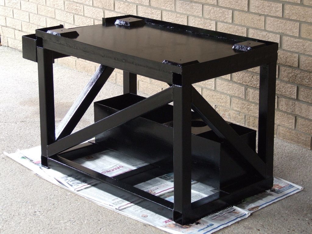
                    Agreed; it would be better to forget the beam and bolt the lathe to the angles at each end of the frame. That way the structure resisting torsion is much larger and stiffer. Clearly the actual loads imposed by cutting forces haven't been thought through. This is the stand I made from 50mm square ERW tubing for my CNC mill:

                    tormach stand me.jpg

                    Andrew

                    #607280
                    duncan webster 1
                    Participant
                      @duncanwebster1

                      Andrew's solution is far the most rigid, but I must challenge Bazyle assertion that tube is not rigid. Comparing a 4" OD 1/4" wall tube to a round bar 1.93" diameter (same mass per unit length), the tube is 7 times more rigid in torsion. I haven't worked out the stiffness of a 3/8*7.85" flat plate, but you don't see many flat plate torsion members in structures do you. Andrews space frame structure is effectively a very large tube. Hot finished tube won't have much locked in stress, and you could always get it stress relieved if you were that worried. A little thing like taht would go in with a big fabrication, so some kind words and folding money would suffice

                      #607285
                      Nicholas Farr
                      Participant
                        @nicholasfarr14254

                        Hi, fundamentally I can't see anything wrong with the basic design in the video, however I do think the angles at each end of the beams lack depth and would be better with an angle with one side the same depth as the beam or a piece of plate the same depth as the beam bolted / welded to the angles or a piece of channel the same depth, no harm in milling the mounting positions as you would be starting with a reasonable flat plain and just about every machine that I've worked on in industry that incorporates a frame or beam that has (for example) pumps plus motors, have plates welded on and milled at the mounting areas, but shimming is still often needed for shaft alignment reasons. All steel sections can bow sage twist etc, no matter how large or thick or shape it is, but any type of frame will increase rigidity, but even frames can flex to some degree. Sometimes if things are not allowed to flex a little, they fracture in some area.

                        Regards Nick.

                        #607286
                        Hopper
                        Participant
                          @hopper

                          My Drummond was on a bench made from a rectangle of 5/16" thick flat plate with a leg welded to each corner. It was very flexible. As the Drummond is an anvil-type bed with the four mounting bolts at the headstock end, you could see a noticeable bow in the flat plate where the weight sagged it. Not at all rigid. I ended up welding a ladder frame under the plate, made from 1.5" or 2" angle iron. A piece running full length front and back and welded to the leg at each end, then cross pieces at each end and where the lathe mounting bolts went so weight was borne by the frame not the flat plate. Then a ring of smaller square tube around the four legs halfway down to sit a wooden shelf on. That fixed it.

                          #607300
                          SillyOldDuffer
                          Moderator
                            @sillyoldduffer
                            Posted by Hopper on 25/07/2022 09:57:44:

                            It seems needlessly complicated and not particularly rigid,

                            Over engineered in some respects and under in others. I don't think there's any doubt it would do the job, but the absence of cross-bracing is a design error, albeit easily fixed. Cross-bracing is needed to stop the rectangular frame flexing in and out of parallelogram form. Without cross-bracing the stand is plenty strong enough, but prone to vibrate, especially if the lathe is cutting a badly balanced object. The value of the heavy beam is dubious because it doesn't support anything: the work load is taken by the lathe bed, itself a heavy beam designed for that purpose. It also raises the centre of gravity, which is undesirable unless the stand is bolted to the floor.

                            Interesting the beam idea comes from gimbal supported lathes on ships. My earlier understanding was that's not necessary on a ship; I could be wrong. But it's definitely not necessary in a shed!

                            I liked the honest and open way the design logic is explained. This isn't one of those awful videos containing great gobs of naive bad practice.

                            Although I wouldn't go out of my way to buy U and box section girders to make one, it's a reasonable answer with advantages if cheap scrap is on hand. Mentionef at the end that a wooden or concrete beam would do; correct. Actually I think reinforced concrete would be best answer of all because the extra mass would soak up vibration. Heavy cast-iron and granite slabs have the same effect.

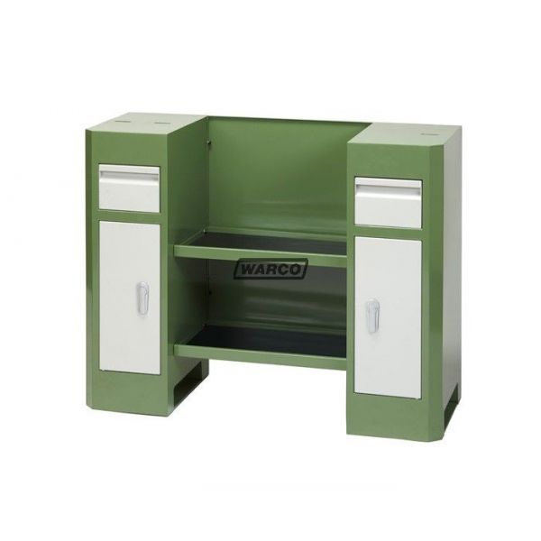
                            Strengthwise, it's what's under a lathe's feet that matters most. In comparison, this example from Warco is a typical modern sheet steel stand, ie designed in the 1930s.wm-250-lathe-stand.jpg

                            It features:

                            Two stiff box columns taking the weight of the lathe down to ground via the lathes feet. The columns are made of heavy gauge steel, bent at the corners to provide rigidity, and the sheet construction provides automatic cross-bracing throughout.

                            Underneath the column bases are solid sheet steel to reduce ground pressure.

                            Horizontal coupling between columns is provided mainly by the lathe bed, helped by the shelves and the tray, but they don't bear any of the lathe load. For convenience, the inside of the columns can be used as storage space.

                            Finally, the two columns are cross-braced by a bolt-on sheet-steel back. The result is strong by design and far more economical that cast-iron stands. If the owner doesn't mind an open frame, the same effect can be created by welding angle into verticals and cross-braced horizontals. Strength to support several hundred kilos is relatively easy: it's harder to minimise flexing and vibration.

                            Dave

                            Edited By SillyOldDuffer on 25/07/2022 13:51:07

                            #607305
                            Bazyle
                            Participant
                              @bazyle

                              A variant on SOD's cabinets is brick piers. You can always find some free bricks in a skip so the cost is just a bag of cement (which is a horrendous price since lockdown). Big drawback is that you really have to have settled on your shed layout first.

                              #607319
                              Nicholas Farr
                              Participant
                                @nicholasfarr14254
                                Posted by SillyOldDuffer on 25/07/2022 13:42:35:

                                Posted by Hopper on 25/07/2022 09:57:44:

                                It seems needlessly complicated and not particularly rigid,

                                Over engineered in some respects and under in others. I don't think there's any doubt it would do the job, but the absence of cross-bracing is a design error, albeit easily fixed. Cross-bracing is needed to stop the rectangular frame flexing in and out of parallelogram form. Without cross-bracing the stand is plenty strong enough, but prone to vibrate, especially if the lathe is cutting a badly balanced object. The value of the heavy beam is dubious because it doesn't support anything: the work load is taken by the lathe bed, itself a heavy beam designed for that purpose. It also raises the centre of gravity, which is undesirable unless the stand is bolted to the floor.

                                Interesting the beam idea comes from gimbal supported lathes on ships. My earlier understanding was that's not necessary on a ship; I could be wrong. But it's definitely not necessary in a shed!

                                I liked the honest and open way the design logic is explained. This isn't one of those awful videos containing great gobs of naive bad practice.

                                Although I wouldn't go out of my way to buy U and box section girders to make one, it's a reasonable answer with advantages if cheap scrap is on hand. Mentionef at the end that a wooden or concrete beam would do; correct. Actually I think reinforced concrete would be best answer of all because the extra mass would soak up vibration. Heavy cast-iron and granite slabs have the same effect.

                                Strengthwise, it's what's under a lathe's feet that matters most. In comparison, this example from Warco is a typical modern sheet steel stand, ie designed in the 1930s.wm-250-lathe-stand.jpg

                                It features:

                                Two stiff box columns taking the weight of the lathe down to ground via the lathes feet. The columns are made of heavy gauge steel, bent at the corners to provide rigidity, and the sheet construction provides automatic cross-bracing throughout.

                                Underneath the column bases are solid sheet steel to reduce ground pressure.

                                Horizontal coupling between columns is provided mainly by the lathe bed, helped by the shelves and the tray, but they don't bear any of the lathe load. For convenience, the inside of the columns can be used as storage space.

                                Finally, the two columns are cross-braced by a bolt-on sheet-steel back. The result is strong by design and far more economical that cast-iron stands. If the owner doesn't mind an open frame, the same effect can be created by welding angle into verticals and cross-braced horizontals. Strength to support several hundred kilos is relatively easy: it's harder to minimise flexing and vibration.

                                Dave

                                Edited By SillyOldDuffer on 25/07/2022 13:51:07

                                Hi Dave, I fail to see where the beam has raised the centre of gravity in the ones shown in the video, any more than the Warco example that you have shown or if it was simply bolted to a workbench.

                                Regards Nick.

                              Viewing 14 posts - 1 through 14 (of 14 total)
                              • Please log in to reply to this topic. Registering is free and easy using the links on the menu at the top of this page.

                              Advert

                              Latest Replies

                              Home Forums Manual machine tools Topics

                              Viewing 25 topics - 1 through 25 (of 25 total)
                              Viewing 25 topics - 1 through 25 (of 25 total)

                              View full reply list.

                              Advert

                              Newsletter Sign-up