Basic Clock Design

Advert

Basic Clock Design

Home Forums Clocks and Scientific Instruments Basic Clock Design

Viewing 25 posts - 151 through 175 (of 331 total)
  • Author
    Posts
  • #236292
    Ajohnw
    Participant
      @ajohnw51620

      Does any one have any ideas of what parts are about that could be used / adapted to make up an electronic remontoire. Preferably suitable for battery operation with a reasonable life.

      John

      Advert
      #236318
      John Haine
      Participant
        @johnhaine32865

        John, do you mean rewinder or remontoire? And by electronic do you mean electric?

        Having dug in my memory a bit about the Clock B presentation last year, I think actually what their rewinder does is the following. It doesn't use a differential, rather there is a dc motor driving a worm that engages with a wheel on the hour wheel arbor. The motor and worm is mounted on a carriage that is picoted on that arbor, and also has a long lever that carries the brass weight visible on the phot that you posted. Also on the carriage is a mercury tilt switch (or two?) that senses when the lever has dropped down to its "rewind" position and when it has been raised to its "stop rewind" position. Those could be replaced nowadays with an Arduino and an accelerometer for sensing and control (what do I mean "these days" – the clock was only completed a couple of years ago!). I would have thought it would be easy to calculate the energy needed, making reasonable allowance for the motor efficiency, gear friction etc, to see what life was possible with a battery supply. A small solar panel could recharge the battery (possibly supplemented by an LTD Stirling engine?).

        Another approach that I've been mulling over is to reverse the system, so a small motor drives the input to the remontoire proper, keeping it wound to the correct tension, so the motor's running is controlled by the remontoire. Then the motor would drive the train from the "fast" end, opposite to standard practice. Potential problem with these schemes is motor lifetime, assuming a brushed motor.

        #236324
        Bazyle
        Participant
          @bazyle

          If you are going to end up electric powered why not make the ME Jubilee clock. This is a starter for ten, it has been updated in later articles and there is a short pendulum version I think.

          Edited By Bazyle on 26/04/2016 17:49:36

          #236333
          Ajohnw
          Participant
            @ajohnw51620

            Thanks Bazyle. Nosing around I found these

            **LINK**

            **LINK**

            **LINK**

            **LINK**

            The first one is interesting.

            John

            =

            #236363
            Ajohnw
            Participant
              @ajohnw51620

              Sorry John. Last time I was reading this I just read the last post.

              From what I can gather clock b used a harrison style remontoire on the escapement and some other method of rewinding. I think I've seen mention of every 20min for that but no mention of how other than by a motor. It's a pity there isn't a decent video of it about. Maybe some one close could go and take a good one.

              I want what ever is used to be as mechanical as possible so a weight remontoire or some sort of rewind system would be ideal. The question really is the best and quietest way to drive it.

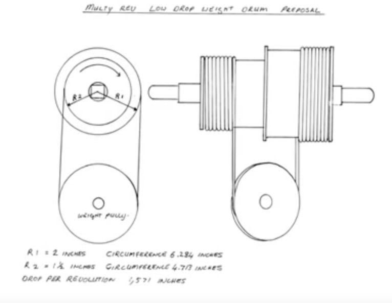
              While nosing about I came across a totally OTT clock that has featured in the BHI magazine several times. It uses weights but with unusual drums.

              strangeweightdrum.jpg

              Not thought it through but as it lets some out is winds some of it back in so more turns can be obtained with a given drop.

              John

              #236383
              jaCK Hobson
              Participant
                @jackhobson50760

                There are videos of clock B about

                http://www.guinnessworldrecords.com/news/2015/4/video-how-%E2%80%9Cperfect-clock%E2%80%9D-redefines-timekeeping-history-300-years-on-377653

                I guess copyright could be a little complicated. At the moment it is still inside the Greenwich Observatory workshop and only viewable through a window. Not sure if pictures are allowed in the museum. And the clock is only on-loan.

                #236411
                Ajohnw
                Participant
                  @ajohnw51620

                  I think that is the only one Jack and too much chuntering and not enough of the clock really.

                  surprise The winding drum can turn an 11ft drop into a 17" one. Lots of loss of torque though.

                  blushMy maths are probably screwball there but it will do for now, For 132" coming off one 115 goes on the other,

                  John

                  #236428
                  John Haine
                  Participant
                    @johnhaine32865

                    AjohnW – yes, as I said, a Harrison remontoire on the escapement and the winding mechanism I described on the hour wheel. I guess the OTT clock you mention is the Schroeder clock, also by Martin Burgess, and recently described in HJ by Doug Bateman? I've tried making one of those drives – never got it to work, probably should have used a bigger weight.

                    #236443
                    Ajohnw
                    Participant
                      @ajohnw51620

                      The weights do look a bit big John. It's shown here and on youtube

                      **LINK**

                      With the sizes he gives it should give the same performance as a weight of 1/8 the size less any losses.

                      The clock made me thing of one of Michael's shiny gearboxes. Wonder how good the time keeping is.

                      John

                      #236643
                      James Alford
                      Participant
                        @jamesalford67616

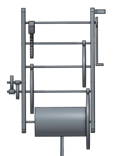
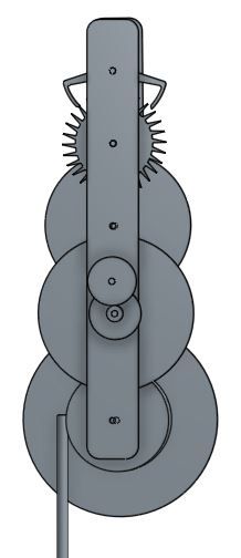
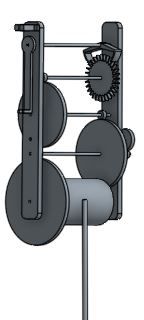
                        Slowly progressing with my drawings. At the same time as designing the clock, I am learning CAD for the first time. I am using Onshape which seems generally to be all right, but seems to do odd things at times, for no apparent reason. I had to draw the pendulum suspension block several times as part way through adding other parts to the assembly, the block split into its components parts and appeared to fall apart.

                        The width between the frames is currently arbitary and will be set later once I have worked out hw large the winding barrel needs to be. Using the idea of a looped rope with pulleys, I should be able to get seven of eight days running time from a four foot drop.

                        I have settled on the following gearing. It may not be ideal, but it all seems to fit and look generally fine. I know that it still uses ten leave pinion in the train, but I am struggling to devise a better ratio that fits together.

                        30 tooth escape wheel followed by:

                        12:90

                        12:96

                        12:120 for the barrel wheel

                        I have 10:30 and

                        8:32 for the hour and minute hands.

                        As mentioned before, the frames are merely shown to hold the wheels and aroburs in place and are not the final design or size.

                        side flat.jpgfront.jpgside.jpg

                        #236651
                        Ajohnw
                        Participant
                          @ajohnw51620

                          I don't know how many teeth you have on the escapement wheel but I was reading that the pallets usually span 90 degrees so 7 1/2 teeth on a 30T wheel and 15 on say a 60 etc. 7 1/2 becomes 7 in that spread sheet I posted.

                          Just a comment in a book. Like most things in this area not much info about.

                          John

                          #236663
                          Michael Gilligan
                          Participant
                            @michaelgilligan61133

                            Not really 'on topic', James, but I think it worth linking this blog

                            He is covering the build of one of the Peter Heimann Regulators that Ajohnw has mentioned several times.

                            Obviously an engineer rather than a 'clockmaker' … it makes interesting reading.

                            MichaelG.

                            #236701
                            Ajohnw
                            Participant
                              @ajohnw51620

                              angel I must be on commission Michael. I have no connection at all but feel that as clock books go it's very good value and actually does what it states on the cover. Some don't. There are 2 designs in it and as he suggests they needn't be followed slavishly.

                              The design shown in the blog is unusual in some ways. There are no chimes. It's month going and uses 2 weights which give it a certain amount of symmetry which is usually lacking in regulators. Both designs are aimed to be pretty good time keepers.

                              John

                              #236730
                              Ajohnw
                              Participant
                                @ajohnw51620

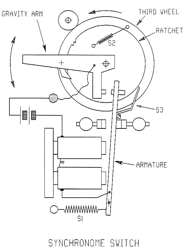
                                This is a rough layout of an "electric remontoire".

                                sychronomeremontoire.jpg

                                S3 locks the remontoire wheel when the solenoids operates. It's driving the escape wheel pinion and the hour and min wheels before it so is intended to be the only source of power.

                                Harrison used the same style of maintaining spring (S2) on his escape wheel remontoire but used 2 springs rather than one.

                                Sometime when done mechanically this sort of arrangement is used to cause one of the hands to jump at the correct interval rather than move slowly in the usual way.

                                Suitable sources of coils and contacts might be relays. The type with clear plastic covers that can be pulled off.

                                John

                                #236827
                                James Alford
                                Participant
                                  @jamesalford67616

                                  Michael,

                                  Thank you for the link to the blog. I have been reading this for a while and have found it very interesting.


                                  John,

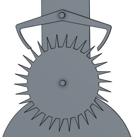
                                  My escape wheel has 30 teeth and the arms of the pallets are at 90 degrees. They span 7 1/2 teeth and have an angle of either 1 or 2 degrees (drop?): I cannot recall which I drew. I know that in the drawing below, one pallet hits the teeth of the wheel. This is because I cannot work out how to rotate the wheel in the CAD drawing.

                                  pallet.jpg


                                  Edited By James Alford on 30/04/2016 09:07:37

                                  #236828
                                  Michael Gilligan
                                  Participant
                                    @michaelgilligan61133

                                    idea Let's borrow this animation from Wikipedia:

                                    **LINK**

                                    MichaelG.

                                    Edited By Michael Gilligan on 30/04/2016 09:17:59

                                    #236829
                                    James Alford
                                    Participant
                                      @jamesalford67616

                                      Michael,

                                      I have found plenty of animations online, but am stuck trying to rotate the wheels in my own drawings. It is possible to animate some elements of assemblies in Onshape, but, so far, my designs have remained stubbornly inanimate. Still, I shall persevere.

                                      James.

                                      #236832
                                      Michael Gilligan
                                      Participant
                                        @michaelgilligan61133

                                        James,

                                        Sorry … I was only trying to provide a convenient illustration, for the convenience of others who might be following the discussion.

                                        I will try not to interfere any further.

                                        MichaelG.

                                        #236835
                                        James Alford
                                        Participant
                                          @jamesalford67616

                                          Michael,

                                          I did not think that it was interfering, but that my original post was unclear! I would prefer your contributions to continue, please.

                                          JAmes.

                                          #236856
                                          Ajohnw
                                          Participant
                                            @ajohnw51620

                                            I found the blog interesting too Michael. One thing I noticed was probably a need to take some care when taking a wheel blank from one machine to another but that may just be an impression from shots of making the pinions – sticking a mandrel in a 3 jaw chuck doesn't seem to be very sensible to me. That lead me to understand why some cut the teeth on the lathe.

                                            Reading a bit more on the dead beat angle in 2 books 90 degrees is ideal. One reckons that major departures makes things more critical so manufacturers generally use it. The other reckons it minimises friction but on large wheels using it will add more inertia and hence increase friction that way so on large wheels it's better to increase it. The book I mention states that this area is the most important one in the clock. Another points out that they can be made in two parts and turned to get precise rads – slot to hold each half in a piece of bar. Which ever I would use the spreadsheet for the design as it shows a good way of getting the impulse faces correct.

                                            For a clock I'm going to call John's Folly. Nice double meaning. I'm inclined to use Brocot but am not sure that I have design information where the wheel finishes up looking much like a dead beat one. A Riefler is vaguely similar but I wouldn't be keen on applying the impulses to the suspension as I doubt if I could sort that out. On the other hand I can't see why this couldn't be used in a conventional fashion. This one appears to use a slope to provide the impulse where as the Brocot uses the rad on the pin. The pin pallet also uses a slope and it seems can be rather good if made correctly.

                                            Not too clear on slope – the slope is on the wheel rather than part of the pallet.

                                            Any views?

                                            blush I don't want to hyjack the thread but thought some discussion might be of use. It seems to be getting a fair number of views.

                                            John

                                            Edited By Ajohnw on 30/04/2016 11:35:24

                                            Edited By Ajohnw on 30/04/2016 11:47:35

                                            #236861
                                            Russell Eberhardt
                                            Participant
                                              @russelleberhardt48058

                                              John, the Brocot escapement is a dead beat escapement. The important design point is that the front face of the escape wheel tooth is radial so that it is tangential to the pallet and thus avoids recoil. It is easy to make and set up hence its use in better quality mass produced mantel clocks, often with a visible escapement and jeweled pallets.

                                              Russell.

                                              #236870
                                              Michael Gilligan
                                              Participant
                                                @michaelgilligan61133
                                                Posted by Ajohnw on 30/04/2016 11:32:09:

                                                … That lead me to understand why some cut the teeth on the lathe.

                                                .

                                                yes That's probably a very worthy topic for a thread of its own, John.

                                                Yes, its very common for [Watchmakers and] Clockmakers to use the lathe headstock for dividing, and a spindle on the vertical slide for the cutters. … The arrangement has a great deal of merit; especially when we look at the antics required to put a small dividing head on a small milling machine. dont know

                                                MichaelG..

                                                #236873
                                                Ajohnw
                                                Participant
                                                  @ajohnw51620

                                                  Thanks Russell. That's what I thought was going on so could work from scratch myself. I have had clock repair periods but haven't had to adjust one but that all started with a book which shows the degree of adjustment that's available even by rotating the pins slightly. My Pultra came with a precision x-y table so no problem drilling the holes either but any miller could do that anyway. The other aspect is that they can be jewelled – not a cheap option but worth it if the clock works. The available pins are a bit thin though, The biggest I can find is 2.35mm dia. laugh I have no idea what the UTS is.

                                                  The fact that things meet square on made me wonder about other similar arrangement. I suspect that when I start digging up info on Riefler I'll find it has to impulse via the spring suspension. It's another attractive one though from a making point of view. It uses 2 escape wheels right next to each other. One has a slope for the pin to run on to provide the impulse. Using 2 wheels means that this one could be burnished easily and adjusted by rotating it against the other wheel which has the usual form. I'd guess that's why he chose to use 2 wheels. It seems the pin pallet can offer near similar levels of performance with a pendulum but I suspect it would be a pig to make.

                                                  Maybe all OTT but years ago I bought two second hand volumes of the clock maker. One of the articles has a telling point. The lack of very high precision designs. It looks like these must include some sort of remontoire some where to me. A nice simple one. indecision It just means a few more bits to make and probably some trial and error. The designs in clockmaker are far from simple. In fact it turned out that the one initially shown in one article didn't work out..

                                                  John

                                                  #236878
                                                  Russell Eberhardt
                                                  Participant
                                                    @russelleberhardt48058
                                                    Posted by Ajohnw on 30/04/2016 13:08:24:

                                                    The other aspect is that they can be jewelled – not a cheap option but worth it if the clock works. The available pins are a bit thin though, The biggest I can find is 2.35mm dia.

                                                    That will determine the diameter of the escape wheel as the pallet diameter is the pitch of the escape wheel less the drop.

                                                    Russell.

                                                    #236893
                                                    Ajohnw
                                                    Participant
                                                      @ajohnw51620
                                                      Posted by Michael Gilligan on 30/04/2016 12:55:24:

                                                      Posted by Ajohnw on 30/04/2016 11:32:09:

                                                      … That lead me to understand why some cut the teeth on the lathe.

                                                      .

                                                      yes That's probably a very worthy topic for a thread of its own, John.

                                                      Yes, its very common for [Watchmakers and] Clockmakers to use the lathe headstock for dividing, and a spindle on the vertical slide for the cutters. … The arrangement has a great deal of merit; especially when we look at the antics required to put a small dividing head on a small milling machine. dont know

                                                      MichaelG..

                                                      I think it's more a case of needing some care when transferring to the miller Michael and being sure things are reasonably line up, square etc.

                                                      I came across this site which may be of interest, or reassuring in my case.

                                                      **LINK**

                                                      Not that the site doesn't have a vested interest.

                                                      As these will need rather precise axial alignment I feel that clock makers pins would be a good idea when plates are held together for machining etc. They cost peanuts but there doesn't seem to be any reamers available for them. The pins are tapered. ??????????????????????

                                                      I'm pretty sure Burgess found that ball races aren't a good idea on the escapement and used PEEK instead.

                                                      I've been looking for jewel holes with a decent bore, say 1 1/2mm plus but PEEK ones are about on the web.

                                                      John

                                                    Viewing 25 posts - 151 through 175 (of 331 total)
                                                    • Please log in to reply to this topic. Registering is free and easy using the links on the menu at the top of this page.

                                                    Advert

                                                    Latest Replies

                                                    Viewing 25 topics - 1 through 25 (of 25 total)
                                                    Viewing 25 topics - 1 through 25 (of 25 total)

                                                    View full reply list.

                                                    Advert

                                                    Newsletter Sign-up