Aluminium thread strength

Advert

Aluminium thread strength

Home Forums General Questions Aluminium thread strength

Viewing 17 posts - 26 through 42 (of 42 total)
  • Author
    Posts
  • #367519
    Neil Wyatt
    Moderator
      @neilwyatt

      I wonder if using "With most metals the ratio of shear to tensile stress is in the range 65% to 70%" as the strap line for the next issue will get me the order of the boot?

      Accessible articles on metal properties for the 'average joe(sephine)' are most welcome!

      Neil

      Advert
      #367549
      DrDave
      Participant
        @drdave

        I am enjoying this topic; lots of good info. But they say that if you ask two Stress Engineers the same question, you will get three different answers! I was somewhat more conservative than Richard when I was a Stress Engineer. I had two rules of thumb that I used for stressing threaded holes:

        1) At ultimate load (the load at which the structure can deform but shall not break), the effective thread length is 1D, and

        2) If you want to be able to get the bolt out again after it has been in service, then assume that the first thread takes half limit load (at limit load, the structure shall not deform)

        I developed these rules over the decades that I did stress analysis of aerospace structures. This does not mean that I am right & Richard is wrong, just how different people approach this complex subject.

        #367557
        duncan webster 1
        Participant
          @duncanwebster1

          This website goes into thread depth in some depth (sorry)

          **LINK**

          #367558
          Neil Wyatt
          Moderator
            @neilwyatt

            More seriously, we don't know the application.

            If it's fit and forget (which I suspect it is) I would use M5 screws straight into the bar.

            I recently fitted a telescope wedge to a 6082 tube of 76mm diameter and 3mm thickness with two (supplied) M4 cap heads into the tube. I'd wager it would take my weight. The critical issue is not overtightening the fixings.

            Neil

            #367566
            Absolute Beginner
            Participant
              @absolutebeginner

              Hi All,

              Well, I didn't expect quite that number of replies. So again many thanks for all answers. All read and greatly appreciated. Perhaps in some areas my description was lacking somewhat as its always difficult when describing things on forums. To try and put some minds at rest, for those still wondering, I will try and provide a more exact explanation for completeness.

              I have a 2 inch diameter 5 meter long Aluminium tube approx 1/4 inch thick – think of Aluminium scaffolding pole

              I need to fasten a piece of aluminium bar to its surface, i.e two the surface of the 2 inch diameter on the 5 meter length. The aluminium bar measures 150mm Long x 40mm high x 8mm wide/thick

              I was referring to bolting through the 2 inch tube into the bar, the interface with the bar is onto the 8mm face of the aluminium bar, so as a few people have pointed out not much meat left in 8 mm thick Aluminium bar after either tapping through or making clearance holes and a nut to secure it via the 8mm face/thickness. Though there is some 40mm height of material. Hence the need perhaps to go to 10mm thickness, or reduce the bolt diameter.or both smaller bolt and 10mm material. Unfortunately, I am unable due to other restraints, to increase the bar thickness above 10mm.

              I hope that clears up any discrepancies. From the kind answers provided I think I will try and tap the aluminium bar with two M5 threads, one close to each end of the ends 135mm apart in the 150mm length to accept stainless bolts with about 18 – 20mm thread engagement in 10mm thick aluminium. All the aluminium is 6082-T6.

              I hope that will be job done. The bar provides an interface bracket for another aluminium tube 30mm diameter, which forms a horizontal joint in a horizontal Truss Beam. ( I know thats as clear as mud now!) Will give it a go and see what happens under some crude testing. Its not a critical truss beam, so no life threatening disaster should it fail.

              Many thanks, and again very much appreciate all the replies

              Gary

              #367609
              SillyOldDuffer
              Moderator
                @sillyoldduffer
                Posted by Absolute Beginner on 16/08/2018 00:13:56:


                Perhaps in some areas my description was lacking somewhat as its always difficult when describing things on forums.

                I have a 2 inch diameter 5 meter long Aluminium tube approx 1/4 inch thick – think of Aluminium scaffolding pole

                I need to fasten a piece of aluminium bar to its surface, i.e two the surface of the 2 inch diameter on the 5 meter length. The aluminium bar measures 150mm Long x 40mm high x 8mm wide/thick

                I was referring to bolting through the 2 inch tube into the bar, the interface with the bar is onto the 8mm face of the aluminium bar, so as a few people have pointed out not much meat left in 8 mm thick Aluminium bar after either tapping through or making clearance holes and a nut to secure it via the 8mm face/thickness.


                Gary


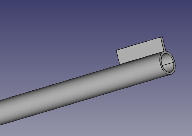
                I suspect that description's not at all as I originally imagined your problem Gary! A picture is worth a thousand words in these situations if you have the technology.

                Do you mean the plate is attached like this?

                ali.jpg

                As shown this is a weak construction because the plate can act as a lever and multiply the force applied to the fixings. (Whether this is likely or not depends on the structure it is connected to and to any stresses than might occur during erection – building a structure can badly stress joints before it is complete.)

                Passing bolts through both sides of the tube helps considerably. (This is what I think you describe doing.)

                alipin.jpg

                Two or more bolts in this arrangement much reduce the effect of leverage.  Note that, in this arrangement. leverage doesn't stress the threads. Rather, when sideways leverage is applied, the forces act more on the bolts and the tube, which might snap or deform.

                You said in the original question 'I need to try and create the strongest joint possible.' If it really needs to be strong, I think we need more information. I like to think in terms of 'what will fail first' and this can't be done without a more detailed description. The answers so far cover the strength of threads, which may be good enough if the load on the plate is in the right direction. If the load isn't perpendicular to the thread other failure modes are possible. The direction of the forces applied matters as much as their intensity. A 5 metre scaffold pole is one hell of a lever…

                Dave


                Edited By SillyOldDuffer on 16/08/2018 10:47:14

                #367613
                Emgee
                Participant
                  @emgee

                  Hi Gary

                  If you can machine a 1" radius cut into the long edge of the bar that mates with the 2" diam pole it will give the joint much more rigidity, if you can't do the radius even making a Vee channel will be a benefit.

                  Emgee

                  #367627
                  Alistair Robertson 1
                  Participant
                    @alistairrobertson1

                    Many years ago we used a lot of Italian made gearboxes and occasionally a couple of 8mm bolts would strip their thread for some reason. Using an insert was not really an option as there was a cross-hole in the way.

                    When we were having a look at another failure, one of our more experienced (older!) engineers said "replace the bolt with a 5/16" BSW one, a 60 degree thread is no use for aluminium!"

                    After negotiation with the gearbox manufacturer they supplied some boxes undrilled. We drilled and tapped them and had no more bother. About a year later the manufacturer started tapping the critical holes BSW and we never had another problem in the next 20 years we used them. The bolts are listed in their parts list as metric 7.97mm x 1.39mm pitch, (5/16BSW!)

                    #367630
                    Michael Gilligan
                    Participant
                      @michaelgilligan61133
                      Posted by Alistair Robertson 1 on 16/08/2018 11:36:46:

                      … The bolts are listed in their parts list as metric 7.97mm x 1.39mm pitch, (5/16BSW!)

                      .

                      Sweet !

                      MichaelG.

                      #367704
                      mark costello 1
                      Participant
                        @markcostello1

                        Why would 5 ° make a difference in Aluminum threads?

                        #367708
                        DrDave
                        Participant
                          @drdave
                          Posted by mark costello 1 on 16/08/2018 20:41:52:

                          Why would 5 ° make a difference in Aluminum threads?

                          The (nominal) tapping drill sizes are 6.6mm for the 5/16 BSW and 6.8mm for M8. This gives a smiggion more area in the aluminium & thus a greater strength. The smaller tapping drill is partly due to the 5 deg difference and partly due to the Whitworth thread being coarser (1.41mm vs. 1.25mm).

                          #367717
                          Neil Lickfold
                          Participant
                            @neillickfold44316

                            The BSW thread form is stronger in weaker or notch sensitive materials due to it's radius on the root and crest. The metric and the UNC form, has sharp edges on the crest of the thread form.

                            Neil L

                            #367833
                            Absolute Beginner
                            Participant
                              @absolutebeginner

                              Hi Dave,

                              What as super drawing. If only I could do that. I can only just about manage a few lines on Autocad.

                              Your drawing is spot on. Spot on. If you imagine a mirror image of the tube and plate approx 500mm apart and a piece of aluminium tube 30mm diameter connecting from plate to plate you have the whole picture. Its a truss like structure and the plates are at approx 500mm intervals along the length of the 5 meter tube and the aluminium tube links are both horizontal and at 45 degrees like you would see on an aerial mast. As essentially that is what I am trying to make.

                              Gary

                              #367839
                              SillyOldDuffer
                              Moderator
                                @sillyoldduffer

                                Hi Gary,

                                I never got on with AutoCAD either! I used FreeCAD, which, once you've sussed out how it works, isn't difficult. Unfortunately getting started can be downright painful – you can't see the wood for the trees.

                                I once tried to design a 30m steel tower for a ham radio friend abroad to be welded up locally. It was intended to carry an HF yagi and rotator. Bows notation left me a quivering wreck. But it seemed to me that uprights made of scaffold tube, or lighter antenna tubing, would transfer most of the force to ground and that the diagonals are only lightly loaded. Their purpose is to increase stability and reduce the tendency to buckle, not to bear weight themselves. Not critical.

                                A couple of exceptions maybe, both when the tower is being erected. Lifting from horizontal to vertical will put an unusual bending force on the structure. Hoisting the antenna to the top also applies a side load, which will be worse if a fatty climbs the tower to fix the antenna in position. Circumstances changed and it never got built. Just as well – I was out of my depth. Lots of towers have collapsed while being erected, but they're solid once upright especially when guyed.

                                My garden isn't big enough to host a tower, but with enough space I think a light construction up to 10m pivoted on a ground post would be ok for a 100kg on top. The antenna would be attached at ground level – no climbing – and then winched up while bending was controlled by propping with a ladder and ropes. The construction is a lot less worrying if no one climbs it and it can't fall on to someone else's property.

                                Dave


                                Edited By SillyOldDuffer on 17/08/2018 22:09:29

                                #367849
                                Absolute Beginner
                                Participant
                                  @absolutebeginner

                                  Hi Dave,

                                  Well again you are right on target. One of my other hobbies is Ham Radio. For years I have made various antenna towers and mast like you have described. There was once a company here in the uk who manufactured steel telescopic towers. They were based upon triangular lattice sections 6 meters long, of differing dimensions. 16 Inch, 13 Inch and 10 Inch, with some even including a 7 inch section. Raising to approx 75ft. They slid and telescoped within one another. I have made countless copies of these type towers over the years. They will on "Limit" hold a HF yagi with rotator and having a wind area of some 2 square meters and weighing up to 150KG unguided up to 50MPH. I have done so. They are no longer manufactured. There are still loads about "Versatower" is the name of choice, however they are getting old now and also expensive.

                                  The one disadvantage of these towers is the weight. Made of steel they weigh close to 1000kg with the ground post typically another 150KG and needing 2cubic meters of concrete foundation, minimum.

                                  I am looking into fabricating a similar type tower but out of Aluminium. They are made in the States, but not here in the UK. I haven't played around with aluminium much and an a steep learning curve. 6082T-6 seems to be the off the shelf, readily available structural stuff in various tube wall thicknesses.

                                  Hence my somewhat stupidly sounding questions. I am considering and looking into bolting the aluminium tube sections together, with horizontal and diagonal struts, as welding Aluminium is a real art, and welds that cosmetically look good are typically not structurally sound.

                                  Still playing around with ideas, and welcome comments from the forum which has such a wealth of information and knowledgable people, such as yourself.

                                  Many thanks for your thoughts and suggestions, I am going to try a few ideas and see how they look, feel and stand up to some of my testing.

                                  Gary

                                  #367854
                                  Farmboy
                                  Participant
                                    @farmboy

                                    Looking at the problem from a different angle, I wonder if there's any merit in forgetting the flat bar and substituting an eye bolt through the upright? The end of the bracing tube could be cross-drilled and fit over the eye with a bolt through . . . maybe dont know

                                    Not sure how easy it is to find suitable eye bolts though.

                                    Mike.

                                    #367860
                                    JasonB
                                    Moderator
                                      @jasonb

                                      One thing you won'tl get with a welded joint that you will with a screwed one is slipping of the two parts, Most trussed structured get their strength from the fact the two members can't "slip" against each other when the bending load is applied. So any excess clearance in your bolt holes will allow movement.

                                      May need some fitted dowels to stop any movement in the plate/50mm pole joint and the same will apply to your 30mm bracing tubes as any movement in the joints will allow your tower to flex..

                                      Edited By JasonB on 18/08/2018 07:47:53

                                      Edited By JasonB on 18/08/2018 07:48:45

                                    Viewing 17 posts - 26 through 42 (of 42 total)
                                    • Please log in to reply to this topic. Registering is free and easy using the links on the menu at the top of this page.

                                    Advert

                                    Latest Replies

                                    Home Forums General Questions Topics

                                    Viewing 25 topics - 1 through 25 (of 25 total)
                                    Viewing 25 topics - 1 through 25 (of 25 total)

                                    View full reply list.

                                    Advert

                                    Newsletter Sign-up