A Marine Condensing Engine

Advert

A Marine Condensing Engine

Home Forums Work In Progress and completed items A Marine Condensing Engine

Viewing 13 posts - 101 through 113 (of 113 total)
  • Author
    Posts
  • #626927
    BERT ASHTON
    Participant
      @bertashton57372

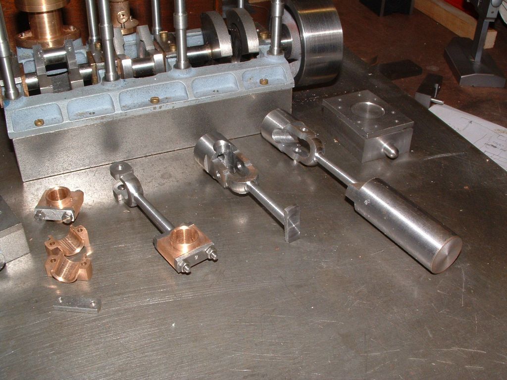
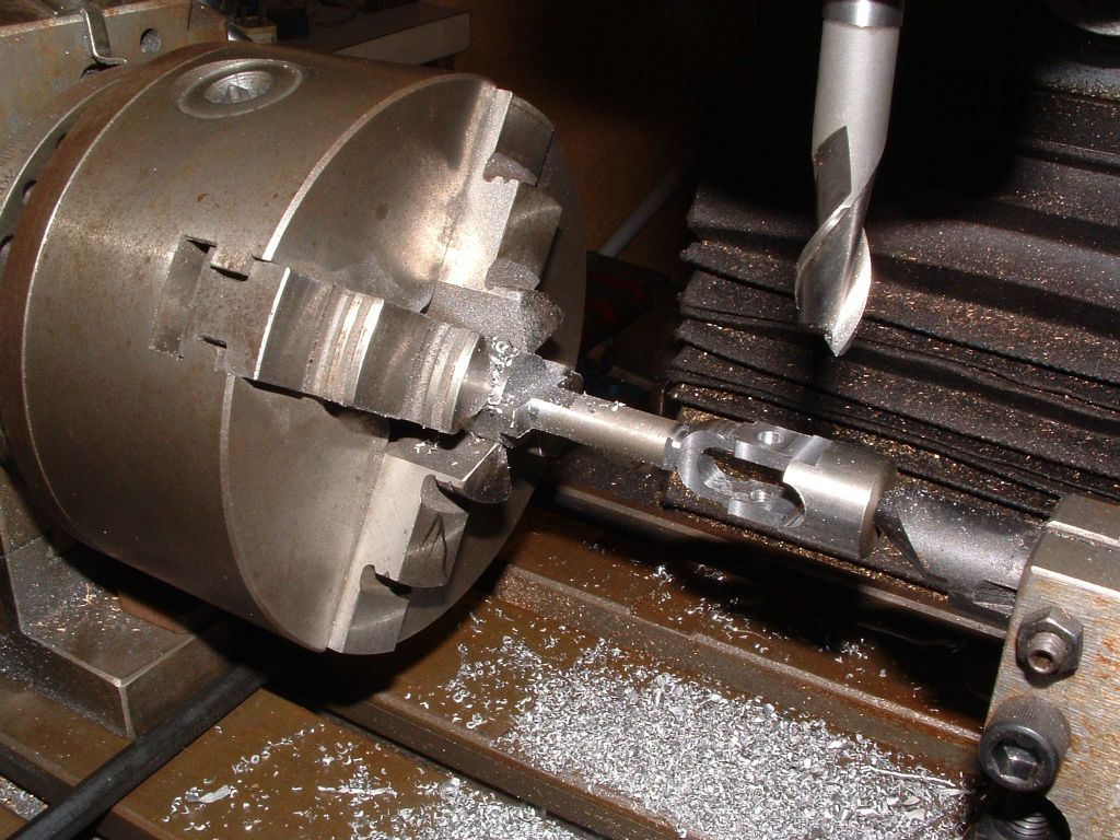
      It was interesting to see a picture of Ramon's con rods. I enclose a couple of pics

      of how I produced mine for the Stuart Triptriple ex 1.jpgle.crank.jpg

      Advert
      #627340
      Zan
      Participant
        @zan

        Hi Ramon. I really enjoy both your and Jason’s builds, very inspiring and providing a wealth of ideas on how to machine some of these complex parts so please keep up the good work!

        Regarding this engine, it looks a fascinating build and a marine engine has been on my bucket list for decades. This one fits the bill as I also really enjoy carving lumps to make the castings. Current engine build is( about to be started is a Mconies diagonal, and the main frames will be ci or aluminium, not decided which yet
        You talk about downloading the drawings as a pdf, but I have searched both your build blog and the one on MEM and can’t find a reference. Could you please provide a link or information of how to obtain them?

        #627343
        JasonB
        Moderator
          @jasonb

          I think they use to be on the now defunked John Tom site.

          #627362
          Ramon Wilson
          Participant
            @ramonwilson3

            Hi Zan, Jason,

            I wasn't aware that the John Tom site was no longer available. If you are talking about the marine engine article I have them on file so could easily send you copies of them if you let me have your email address.

            Good luck with your Mc'Onie – a lovely engine but do check the measurements on width build up between the frames as there are one or two that can lead you astray. Also the position for the governor pedestal – that's dimensioned off the edge of the baseplate at opposite datums. Position it relative to the (assembled) crankshaft position for best results.

            With the complex valve gear I expected mine to have issues with the set up but I worked to the drawings on all components and it ran straight off.


            Best – Tug

            Edited By Ramon Wilson on 03/01/2023 13:34:23

            #644536
            BERT ASHTON
            Participant
              @bertashton57372

              Ramon, Have you any updates on this project?.

              #644565
              Ramon Wilson
              Participant
                @ramonwilson3

                Hello Bert,

                I'm afraid to say that no, it's still as my last posting update. I did finish my plastic project and have begun the slow process of downsizing my workshop.

                It is my firm intention to finish this engine however and hopefully later this year but it will be my last I think. The desire to continue machining in my old age is very low. That's not to say I will stagnate – I've far too much on my plate for that to happen.

                Thanks for asking – I will be back about this project but I don't think it will be until late in the year.

                Kind Regards – Tug

                #699608
                Zan
                Participant
                  @zan

                  Hi tug

                  still not yet started this engine as I want to finish my other three on the go first!  However I’ve just spent some time reviewing the drawings yet again and I discovered that there’s a question about the condenser

                  The original design used 1/16” end plates for the tubes which were soft soldered in place to seal them.  They were attached to the outside end face of the condenser body with 6 ba cks screws  and the covers fitted on top of them  to try to seal them to the casing and to the covers at the same time with the plates squeezed between cover and body.

                  this now means that in order to seal against the body, the the end plate itself will have to be distorted to push it hard against the body, it will be difficult to fit any gasket as it would be destroyed during the soldering operation and of course any sealant cannot be added as there is no gap !    I note with your build the end plates are recessed into the body and do not fit on the outside.  Although I will never run the engine on steam, for completeness I would like it to be built so that it could. Se. Photo in previous listing page from 1/11/22
                  i was wondering what you were using (and how) to seal the steam space from the water space   With the recessed design the end cover cannot now provide the sealing force .  Is it just a massive fillet of jb weld?  The pressures of course are only to near vacuum so we are looking at 14 psi

                  I was also thinking about using copper for the end plates as they would deform to seal more easily


                  I look forward to hearing from you, not seen you posting for a while

                  #699740
                  Ramon Wilson
                  Participant
                    @ramonwilson3

                    Hello Zan,

                    Thanks for your email which alerted me to your post. You are right it has been sometime since I posted save for the initial issues on the change over.

                    Engine wise I have nothing to report but a lot has run under the bridge since last doing so. Hopefully I may be able to get back on to it in the Spring.

                    Re the condenser. I have to confess that initially I misread the drawing and ‘saw it in my head’ from the outset that the plates were recessed. The condenser body was milled to accept such before I realised that mistake. I did consider trying to reclaim it to as it should be but as with yourself, with no intention to run on steam, decided it wasn’t worth it.

                    As the design calls for, the tubes are soldered after the plates are screwed in place. One can only assume the plates would be sealed by some means too as once soldered they would not be removable. The cavities at each end in the covers which are only open to cooling water would then have a gasket to provide a seal. In that case once you commit to fixing the tubes by ‘soldering’ you may as well commit to doing like wise with the tube plates. Obviously far too much heat would be required for that so standard JB weld or similar springs to mind as a suitable means. A paper or liquid gasket should suffice for the covers which is what I shall do on mine. I ran Loctite Bearing Fit around the edges and around the tubes, not so much to seal but to secure.

                    Though I have not made any progress on my version the year has been full with other matters. I have now consolidated my 14 x 14 workshop into 14 x 7 and screened it off. ‘Compact and Bijou’ I’m quite happy with the smaller workshop outcome and it will serve more than enough for anything I am likely to do in future. The larger mill has been sold and currently I’m working on the area left to become a ‘clean’ one.

                    I have hit some health issues this year, nothing serious but enough to have a detrimental effect at times but I’m still maintaining my interest in building and flying control line models and of course plastic modelling. I have several matters to tie up in that direction but I do intend and really hope to be able get back on to the engine next year.

                    Wishing you, and all that look in, a Happy Xmas and here’s to a good and happy New Year

                    #700516
                    Zan
                    Participant
                      @zan

                      Hi   What a cracking idea to use bearing fit for the tubes. One end can be fitted with a conventional gasket and the other fitted when the time comes

                      im currently drawing all the main parts in Fusion  at full size, then it can be scaled and printed out without recourse to the calculator to do the sizes. It also helps me to work out the machining order, and to see all the dimensions which are not too clear in some cases   Not found any mistakes yet!
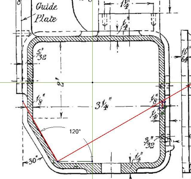
                      Just completed the condenser drawings  but struggling to work out how to cut the internal angle.   Current thinking is either multiple passes with a ball cutter, finish with a file, or set it at an angle then use a small dia fly cutter ( similar to a boring bar]   A standard cutter hits the top edge when it’s tilted.   It’s a complex build and I’m looking forward to starting, but go to paint me loco first!

                      I increased my shop a couple of years ago. Now 25×10 and I can now get in and out without struggling round the Bridgeport

                      merry Christmas to all

                      #700519
                      JasonB
                      Moderator
                        @jasonb

                        Zan, it looks to me that a straight cutter would do it provided you did not have a horizontal split line too far up the side of the condenser. Or would a vertical split be possible as that would give a lot more access.

                        condenser

                        #700530
                        Zan
                        Participant
                          @zan

                          Ah,  thanks for that.   I don’t like the idea of a vertical split could make the assembly  a bit weak and lowering it gets it too close to the bend and possible complications, but the solution just came to me, make the split at two heights with the back being lower. A lot easier! ( as long as it still clears the pump mounting “bosses” at the back)

                          I am so amazed by the authors (Axel) comments like, “obtain a forging for the crankshaft”  and “the patterns will be easy to make”. It was a different era.  I’d be interested to know how many engines  [ if any) were built to his design

                          #700535
                          JasonB
                          Moderator
                            @jasonb

                            There were some casting sets produced about 7 years ago and as far as I know only one of the 5 has been built. Cost to the kit supplier then was $2100 so that would be more like $3000 now so a sale price of $4000 plus would not be unreasonable so it would only be people with deep pockets making from castings these days. See here and the linked thread in the first post.

                            There is also a bar stock one currently featured in ME but not as nice as Ramon’s

                            #700560
                            Ramon Wilson
                            Participant
                              @ramonwilson3

                              Zan – personally I wouldn’t get too hung up on the internal angle as it’s just not that important. I did mine by step milling with a ball nose and filing the high spots off. Calls for nothing more complicated than a list of movements to follow – it’s actual surface finish and/or angle to the outside plays no useful part at all in the scheme of things (save one of personal satisfaction I guess)

                              There are quite a few comments in the original article that can bring a wry smile – and yes it was certainly a different world to today. Just this morning watched a clip of a tool change that was faster than the blink of an eye!

                            Viewing 13 posts - 101 through 113 (of 113 total)
                            • Please log in to reply to this topic. Registering is free and easy using the links on the menu at the top of this page.

                            Advert

                            Latest Replies

                            Viewing 25 topics - 1 through 25 (of 25 total)
                            Viewing 25 topics - 1 through 25 (of 25 total)

                            View full reply list.

                            Advert