CJ18 Pot and switch.

Advert

CJ18 Pot and switch.

Home Forums Beginners questions CJ18 Pot and switch.

Viewing 4 posts - 1 through 4 (of 4 total)
  • Author
    Posts
  • #9555
    Ian Taylor 12
    Participant
      @iantaylor12

      Connections?

      Advert
      #398518
      Ian Taylor 12
      Participant
        @iantaylor12

        I have been trying to replace the potentiometer/switch on my CJ81 mini lathe.In the process connecting wires have become detached from the circuit board and I am unable to find the locations. The wires are still attached to the switch terminals on the back of the pot and the 3 terminals of the pot to the board are intact. If anyone can help I'd be most grateful. Failing direct help can anyone provide a contact email address for Steve Jordan who has in the past made a YouTube video of rewiring a potentiometer – unfortunately it did not show the switch connections on the circuit board or other location. Thanks in hope, Ian.

        #398524
        John Rudd
        Participant
          @johnrudd16576

          Ian,

          Have a look at ….

          https://littlemachineshop.com/info/business_resources.php?ID=1876291636&CAT=1

          Without knowing which board you have fitted, its difficult to tell you……

          #398638
          SillyOldDuffer
          Moderator
            @sillyoldduffer

            Can you post a good photo of the board Ian? It may be possible to work out where the wires go from that. I think from your description it's only the switch wires that have come adrift, not the three speed-control wires connected to the pot?

            How to post photos on the forum here.

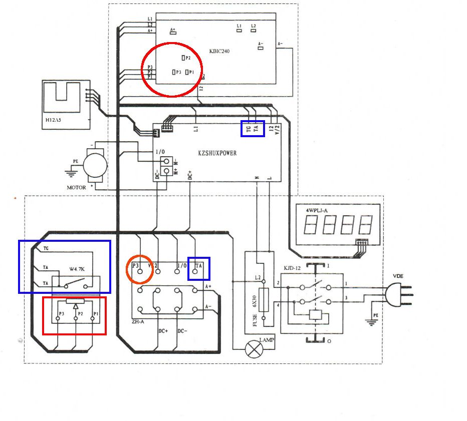
            This circuit pinched from Amadeal's CJ18 Manual may help, assuming your lathe's electronics are as described in it (mini-lathe electronics vary a fair bit, similar rather than identical):

            cj18.jpg

            The red square highlights the 3 speed control wires marked P1, P2 & P3 connected to the potentiometer. These connect to board KBIC240. I believe the board should have 3 tag connectors arranged in a triangle (as shown inside red circle).

            An oddity is that the reversing switch (marked SH-A) also has a connection marked P3. (inside Orange Circle) I don't understand this; the photo might help.

            The switch part of the potentiometer (inside blue box) has three wires, 2 of which ( 'TA' ) are connected together. One of these (doesn't matter which) goes to a terminal on the Reversing Switch; the other goes to a terminal on KZSHUXBOARD as does the third wire 'TG'. TA & TG are highlighted by a blue box.

            Amadeal's drawing probably indicates roughly where on the real board the terminals are to be found, and they could also be marked more-or-less sensibly on the board itself. May be terse abbreviations!

            Hope that helps.

            Dave

            Edit: pesky smiley removed


            Edited By SillyOldDuffer on 04/03/2019 13:35:01

          Viewing 4 posts - 1 through 4 (of 4 total)
          • Please log in to reply to this topic. Registering is free and easy using the links on the menu at the top of this page.

          Advert

          Latest Replies

          Home Forums Beginners questions Topics

          Viewing 25 topics - 1 through 25 (of 25 total)
          Viewing 25 topics - 1 through 25 (of 25 total)

          View full reply list.

          Advert

          Newsletter Sign-up