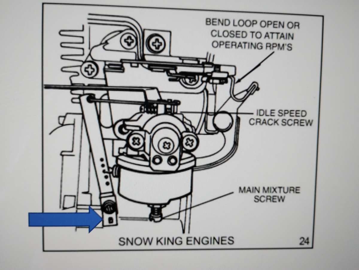
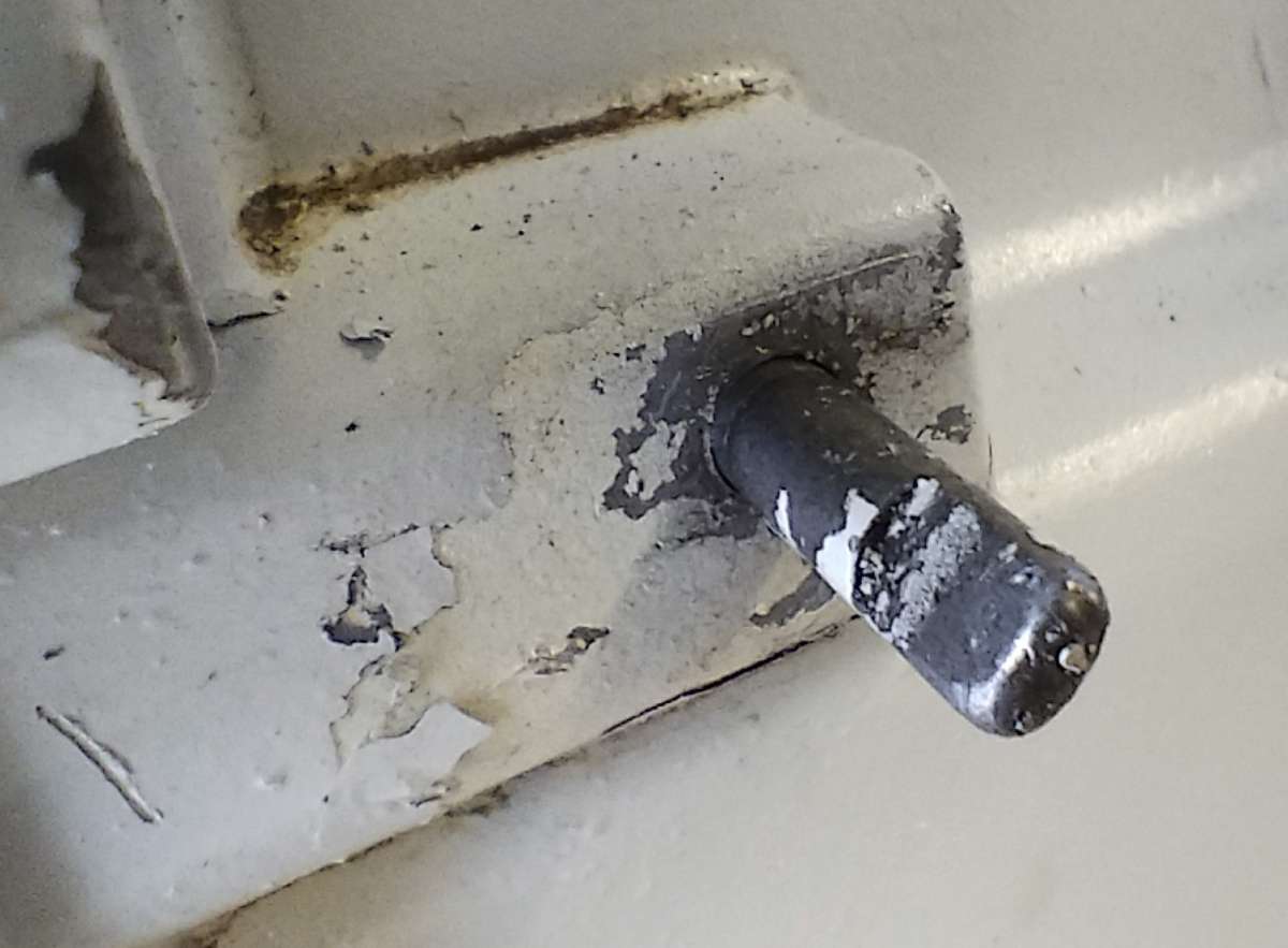
Purpose of pivot on carburettor linkage ? ?
Purpose of pivot on carburettor linkage ? ?
- This topic has 12 replies, 5 voices, and was last updated 13 May 2025 at 10:09 by
 Alan Donovan.

- Please log in to reply to this topic. Registering is free and easy using the links on the menu at the top of this page.
Latest Replies
-
- Topic
- Voices
- Last Post
-
-
4 cylinder rotary valve
Started by:
AStroud
in: Work In Progress and completed items
- 5
-
7 June 2026 at 00:02
alecs
-
Breaking gears in a Myford ML7
Started by:
drnewcomb
in: Manual machine tools
- 10
-
7 June 2026 at 00:00
alecs
-
ChatGPT … getting close to passing the Turing Test
1
2
Started by:
Michael Gilligan
in: The Tea Room
- 15
-
6 June 2026 at 23:18
John Haine
-
New to me Denbigh Power Hacksaw
Started by:
southernchap
in: Manual machine tools
- 1
-
6 June 2026 at 23:17
southernchap
-
digital microscope for poor eyesight
Started by:
bernard towers
in: Electronics in the Workshop
- 3
-
6 June 2026 at 23:11
John Haine
-
Taylor Hobson Pantograph Engraver Model D
Started by:
jaCK Hobson
in: Workshop Tools and Tooling
- 7
-
6 June 2026 at 20:51
Charles Jambon
-
Cheap digital spirit level accuracy
Started by:
Mick Bailey
in: Workshop Tools and Tooling
- 14
-
6 June 2026 at 18:47
vintagengineer
-
Table in the Mk1 Clarkson cutter grinder manual.
Started by:
Andrew Tinsley
in: General Questions
- 3
-
6 June 2026 at 18:12
Andrew Tinsley
-
Band saw
1
2
3
Started by:
Peter Simpson 3
in: Beginners questions
- 23
-
6 June 2026 at 18:02
Adam Harris
-
Tapping Trick
Started by:
Steve Withnell
in: Workshop Techniques
- 10
-
6 June 2026 at 17:43
John Purdy
-
Lightning
Started by:
duncan webster 1
in: Electronics in the Workshop
- 12
-
6 June 2026 at 17:41
peter1972
-
My week this week! My workshop videos
1
2
…
12
13
Started by:
Phil Whitley
in: The Tea Room
- 16
-
6 June 2026 at 16:15
Phil Whitley
-
Replacement Allbrit Draftmaster Protractor Rulers
Started by:
wigan2026
in: Workshop Tools and Tooling
- 6
-
6 June 2026 at 13:43
Grindstone Cowboy
-
Warco GH600 Upgrades (DRO and Bed Protection)
Started by:
Richard Kirkman 1
in: Work In Progress and completed items
- 4
-
6 June 2026 at 12:41
Richard Kirkman 1
-
S,O,D
Started by:
larry phelan 1
in: The Tea Room
- 3
-
6 June 2026 at 09:34
larry phelan 1
-
where to find locomotive / train plans ?
Started by:
zuji miko
in: Beginners questions
- 4
-
6 June 2026 at 09:21
Nicholas Farr
-
Price of A Mk2 Clarkson cutter grinder.
Started by:
Andrew Tinsley
in: General Questions
- 5
-
6 June 2026 at 08:35
Adrian R2
-
Improving a 30 taper fit
Started by:
Andrew Skinner
in: Manual machine tools
- 10
-
5 June 2026 at 19:31
Howard Lewis
-
Myford VMC Spindle Advice Please.
Started by:
Nigel Graham 2
in: Manual machine tools
- 7
-
5 June 2026 at 12:59
Vic
-
Richard B’s Minnie.
Started by:
Richard B
in: Traction engines
- 4
-
4 June 2026 at 21:09
Richard B
-
What Did You Do Today 2026
1
2
…
4
5
Started by:
JasonB
in: The Tea Room
- 33
-
4 June 2026 at 19:59
Nicholas Farr
-
New member..
Started by:
wigan2026
in: Introduce Yourself – New members start here!
- 5
-
4 June 2026 at 16:19
Harry Wilkes
-
24cc DIESEL ENGINE FROM SOLID
1
2
3
Started by:
dean clarke 2
in: I/C Engines
- 13
-
4 June 2026 at 08:35
alecs
-
I wanted to learn 3D cad but couldn’t be bothered…
Started by:
wilson logan 1
in: CAD – Technical drawing & design
- 11
-
4 June 2026 at 07:12
JasonB
-
Starting to use Proxxon MF70
Started by:
barryblundell
in: Workshop Tools and Tooling
- 8
-
3 June 2026 at 23:38
Michael Gilligan
-
4 cylinder rotary valve
Latest Issue

Newsletter Sign-up
Latest Replies
- 4 cylinder rotary valve
- Breaking gears in a Myford ML7
- ChatGPT … getting close to passing the Turing Test
- New to me Denbigh Power Hacksaw
- digital microscope for poor eyesight
- Taylor Hobson Pantograph Engraver Model D
- Cheap digital spirit level accuracy
- Table in the Mk1 Clarkson cutter grinder manual.
- Band saw
- Tapping Trick

