

Myford Capacitor problem?

Myford Capacitor problem?

Home Forums General Questions Myford Capacitor problem?

Viewing 25 posts - 1 through 25 (of 29 total)
  • Author
    Posts
  • #23290
    Chris Trice
    Participant
      @christrice43267
      #151470
      Chris Trice
      Participant
        @christrice43267

        I suspect the start capacitor on my ’84 Myford Super 7 has packed up. One minute the lathe is running fine, next minute, pressing the start button causes a buzzing sound from the motor. I tried this three times and on the fourth attempt, nothing, no buzz, just completely dead. My question really is (a) am I right it’s most likely a burnt out capacitor and (b) am I likely to have done any damage to the motor windings trying to run it? Is there anything else I should check as a possibility?

        #151473
        Les Jones 1
        Participant
          @lesjones1

          Hi Chris,
          It could also be the centrifugal switch on the motor or the contacts on the Dewhurst reversing switch if fitted. If you can photograph the connection box on the motor an also make a diagram of the connections from the cable to the motor and also which terminals the start capacitor is connected to. From that it should be possible to identify the terminals connected to the centrifugal switch.

          Les.

          #151483
          Lambton
          Participant
            @lambton

            Chris,

            Your problem is almost certainly caused by the contacts in the Dewhurst switch that have been arcing and have eventually burned so much that they no longer function properly. I had a similar problem some time ago and found that two of the contacts had actually welded themselves together. Dewhurst switches are not suitable for frequent on/off operations and should only be used in conjunction with a direct online starter simply to provide a F/R function.

            Eric

            #151487
            john fletcher 1
            Participant
              @johnfletcher1

              Dewhurst switches are not really up to the job as Eric has said, they should be used in conjunction with a direct on line starter which has overloads and no volt release. The Dewhurst should be used for altering the direction of rotation of the motor only. Select D.O.R of the motor then press the GREEN button. There are spare un used contacts on a Dewhurst which you may be able to utilise as replacements. Note how the links are positioned before dismantling, but how often do you or me want to run your lathe in reverse. If you have much trouble you may wish to consider obtaining a 3 phase motor and inverter, there are plenty of pre owned ones around, no need to buy an expensive new one. Like there are plenty of pre owned starter available .Ted

              #151493
              Chris Trice
              Participant
                @christrice43267

                If by Dewhurst switch you mean the older style of lever switch, it doesn’t have one. It’s got the control box on the front with a start button for forward and one for reverse. I had the front panel off and all the electrics and contacts look immaculate. I took the cover off the motor and one of the spade connectors on the capacitor has seen better days looking highly corroded. Would I get evidence of continuity through the capacitor using an electric meter if it’s working in the same way I might a fuse?

                #151495
                Nick_G
                Participant
                  @nick_g

                  Disconnect the motor. Wire the motor to a length of flex with a plug on. Switch on.!

                  If the motor runs it eliminates a fault on the motor and points to the control side. – If it does not, then look for a problem at the motor side.

                  Try spinning the motor by hand with power on. (watch fingers.! – Probably best to take the belt off the pulley) 'If' it then runs this can sometimes tell you that the staring capacitor has gone south.

                  Nick

                  #151498
                  Les Jones 1
                  Participant
                    @lesjones1

                    Hi Chris,
                    Using a multimeter on the ohms range will not give a definitive result. Before doing any tests short circuit the capacitor and disconnect at least one of its connections. (It might still have some stored charge and give you a shock.) When you connect a multimeter to a large value capacitor it should first show a fairly low resistance but the reading should increase with time. (Depending on the capacitor and the current from the meter.) It should eventually reach a reading of several meg ohms. Very often capacitors used for this sort of application have a resistor connected across the terminals to discharge them. This would mean that the reading would never reach several meg ohms. It would probably only reach about 470 K ohms. Even if your capacitor behaves like this it could still be faulty with a high internal resistance. If the corroded spade connector was directly on the capacitor it would indicate that the electrolyte was leaking from it. If your multimeter has an AC current range of about 10 amps you could connect it in series with the capacitor. On a WORKING motor you would expect to see a current reading for less than a second after applying power. Identifying the centrifugal switch connections would enable you to do a definitive test on it with you multimeter.

                    Les.

                    #151500
                    Nick_G
                    Participant
                      @nick_g
                      Posted by Les Jones 1 on 05/05/2014 11:08:17:

                      Very often capacitors used for this sort of application have a resistor connected across the terminals to discharge them.

                      Les.

                      Reminds me of 'the good ole days' (30 years ago) when it was considered acceptable to discipline apprentices for doing something wrong. (something serious like forgetting to put sugar in the tea) laugh

                      We would get a capacitor from an old flou fitting and clip out the bleed resistor. Then charge the cap with a 1000 volt Megger (insulation tester)

                      The next step I am sure you can guess.? wink But it resulted in squeaking and an improved ethos to get it right next time. devil

                      Can you imagine the kufuffle if that sort of thing was done today.? surprise lol Back then it was considered 'normal'. But today I would imagine considered similar to walking into a bank brandishing a machine gun.!

                      Nick

                      #151520
                      john fletcher 1
                      Participant
                        @johnfletcher1

                        To eliminate the possibility of a faulty capacitor simply disconnect the capacitor altogether and put a piece of wire in its place, the motor should run. Your local motor re winder will have a replacement capacitor should you need one or maybe a member of the local club will have a spare hanging about doing nothing. I seem to remember all sorts of dangerous practices taking place in the 1950/60 from people who should have known better, good sense now prevails in most cases.Ted

                        #151567
                        Chris Trice
                        Participant
                          @christrice43267

                          I’ve managed to narrow it down to a motor fault. With the motor completely off the lathe and connected to the mains, the motor still buzzes. When I connect a duplicate motor the same way, the new one runs fine. The capacitors have been swapped between motors and both work fine on the good motor but make no difference on the duff one. At least the lathe is running again and I can look at the old motor at my leisure. I’ve no idea what the fault can be. I took it apart and everything seems good but obviously it’s not. The centrifugal switch “appears” to be working as it should and I even cleaned up the contacts before reassembling but the fault remains. A short somewhere maybe?

                          #151586
                          Les Jones 1
                          Participant
                            @lesjones1

                            Chris,
                            I go back to my original request for a picture of the terminal block inside the motor connection box. With that information any of the members that have replied to your post will be able to suggest what tests to do using your multimeter. This could identify an open circuit winding, a short between the two windings or the centrifugal switch being faulty. I would not have dismantled the motor before doing the tests.

                            Les.

                            #151587
                            Lambton
                            Participant
                              @lambton

                              Chris,

                              Single phase current does not produce a rotating magnetic field from the run windings so a second set of start windings are provide at an angle to the main winding to produce a temporary two phase situation. The start winding must however be disconnected very quickly as it will burn out if energised for too long. The centrifugal switch at the back end of the motor cuts out the start winding at about 75% of full speed.

                              The buzzing and lack of rotation of your motor indicates the run winding is OK but the start winding is not operating.

                              From the results of your tests you have now isolated the problem to the start winding circuit. Either the winding itself, its terminations or the centrifugal switch. I suggest that you disconnect and the isolate the start winding (usually yellow and blue on earlier UK made motors) in the terminal box and test for continuity. The action of the centrifugal switch is a bit more difficult to check but this can be done by running the motor up with a second good motor and testing the action of the switch with a meter.

                              Eric

                              #151630
                              Chris Trice
                              Participant
                                @christrice43267

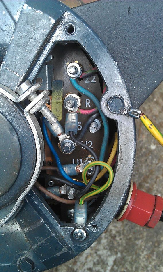
                                Here's a photo as requested:

                                motorwiring.jpg


                                Edited By Chris Trice on 06/05/2014 15:50:47

                                #151633
                                Chris Trice
                                Participant
                                  @christrice43267

                                  The pink and green wires at the top go to the capacitor. The live, neutral and earth wires come in through the lower right to U1, U2 and Earth. The two black wires which control motor direction and go to "R" and (I think) "P" (the lower terminal).

                                  #151643
                                  Lambton
                                  Participant
                                    @lambton

                                    The markings of the terminals of single phase motors can be a bit confusing.

                                    Modern European motors designate the main run windings U1 and U2 with the start windings marked Z1 and Z2.

                                    Older motors use A1 & A2 for the main windings, and start windings can be marked Z & T

                                    The start winding (if is OK) will have a higher resistance that the run winding.

                                    Eric

                                    #151644
                                    Les Jones 1
                                    Participant
                                      @lesjones1

                                      Hi Chris,
                                      Start off by measuring the resistance between "P" and "Z2". You should get a reading of a few ohms. This will be the centrifugal switch in series with the start winding. If you get a high reading either the start centrifugal switch or the start winding are open circuit. I think the blue wire connected to "Z2" and the yellow wire connected to "P" go inside the motor. One will go to the one side of the centrifugal switch, the other will go to one end of the start winding. The other end of the start winding will be connected to the other side of the centrifugal switch. If you got a high reading between "Z2" and "P" (The most likely fault.) we will need to get to the connection point between the start winding and the centrifugal switch to identify which is faulty. Assuming these tests are on the motor NOT connected to the lathe control box measure the resistance between "U1" and "P" and "U1" and "Z2" This reading should be very high. (At least 10 meg ohms.) If you get a low reading there is a short between the windings. (This is very unlikely.) Did you check the centrifugal switch with your multimeter when you had the motor apart or just visually inspect the contacts ?

                                      Les.

                                      #151670
                                      Chris Trice
                                      Participant
                                        @christrice43267

                                        Thanks guys. I'm learning as we go. I probably won't get a chance to get my hands dirty again until tomorrow but I'll try the practical tests you suggest Les. I only looked at the centrifugal switch on the motor shaft visually and operated it manually. It seemed to be in good mechanical order. The contacts it plays against are on the edge of the board photographed. I cleaned the contacts up but didn't try electrically testing them. They're pretty basic and any damage I imagine would be fairly self evident.

                                        #151673
                                        Paul Tummers
                                        Participant
                                          @paultummers57940
                                          Posted by Nick_G on 05/05/2014 11:50:21:

                                          Posted by Les Jones 1 on 05/05/2014 11:08:17:

                                          Very often capacitors used for this sort of application have a resistor connected across the terminals to discharge them.

                                          Les.

                                          Reminds me of 'the good ole days' (30 years ago) when it was considered acceptable to discipline apprentices for doing something wrong. (something serious like forgetting to put sugar in the tea) laugh

                                          We would get a capacitor from an old flou fitting and clip out the bleed resistor. Then charge the cap with a 1000 volt Megger (insulation tester)

                                          The next step I am sure you can guess.? wink But it resulted in squeaking and an improved ethos to get it right next time. devil

                                          Can you imagine the kufuffle if that sort of thing was done today.? surprise lol Back then it was considered 'normal'. But today I would imagine considered similar to walking into a bank brandishing a machine gun.!
                                          Nick

                                          Is this the same way of thinking like with building an electric mouse trap?

                                          #151700
                                          Les Jones 1
                                          Participant
                                            @lesjones1

                                            Hi Chris,
                                            Another failure mode has occurred to me. If the main winding was open circuit the symptoms would appear to be the same. The start winding would be powered (Causing the motor to buzz.) but it would not rotate. So I suggest also checking the resistance of the main winding. To do this measure the resistance between U1 and U2. It should be a few ohms.

                                            Les.

                                            #151899
                                            Les Jones 1
                                            Participant
                                              @lesjones1

                                              Hi Chris,
                                              I will be at Harrogate tomorrow (Saturday) so If you are going you could bring your faulty motor and I could have a look at it for you.

                                              Les.

                                              #151927
                                              Chris Trice
                                              Participant
                                                @christrice43267

                                                Thanks for the offer. I was 50/50 whether to go to Harrogate but unfortunately can't really spare the time. I'm in Kent. However, I did a meter test. I'm getting a reading of 17 with the meter set on 2000 across P and Z2. I'm getting no reading at all on any setting across U1 and P or U1 and Z2 i.e. the meter value of 1 remains unchanged.


                                                Edited By Chris Trice on 09/05/2014 13:36:18

                                                #151929
                                                Chris Trice
                                                Participant
                                                  @christrice43267

                                                  Between U1 and U2, I'm getting a reading of 2 (which is good I think).

                                                  #151934
                                                  Les Jones 1
                                                  Participant
                                                    @lesjones1

                                                    Hi Chris,
                                                    Harrogate would be a long journey for you. I am much closer as you will see from my profile. The reading you are getting (Assuming the units are ohms.) are near to what I would expect. The main winding resistance is a little lower than I would expect and the start winding in series with the centrifugal switch is a little higher than I would expect. (The main winding on the 550 watt motor on my lathe is 4.4 ohms. I could net get at the end of the start winding without taking the motor apart.) When I get time I will see if I can measure the start winding resistance on my pillar drill. I am puzzled by this sentence "I'm getting no reading at all on any setting across U1 and P or U1 and Z2 i.e. the meter value of 1 remains unchanged." It is the value of 1 (ohm?) I do not understand. The reading should be infinity. (Or at least sever megohms.) Up to the" value of 1" bit I understood the reading was infinity.

                                                    Les.

                                                    #151949
                                                    Chris Trice
                                                    Participant
                                                      @christrice43267

                                                      When you turn the meter on to test resistence, it defaults to 1. If you touch the probes of the meter together, it changes. When I touch the appropriate terminals, the default reading of 1 stays on the meter suggesting there is no circuit or continuity of any kind.

                                                      Edited By Chris Trice on 09/05/2014 16:49:59

                                                    Viewing 25 posts - 1 through 25 (of 29 total)
                                                    • Please log in to reply to this topic. Registering is free and easy using the links on the menu at the top of this page.

                                                    Latest Replies

                                                    Home Forums General Questions Topics

                                                    Viewing 25 topics - 1 through 25 (of 25 total)
                                                    Viewing 25 topics - 1 through 25 (of 25 total)

                                                    View full reply list.

