What did you do Today 2018

Advert

What did you do Today 2018

Home Forums The Tea Room What did you do Today 2018

Viewing 25 posts - 1,776 through 1,800 (of 1,832 total)
  • Author
    Posts
  • #384368
    Cornish Jack
    Participant
      @cornishjack

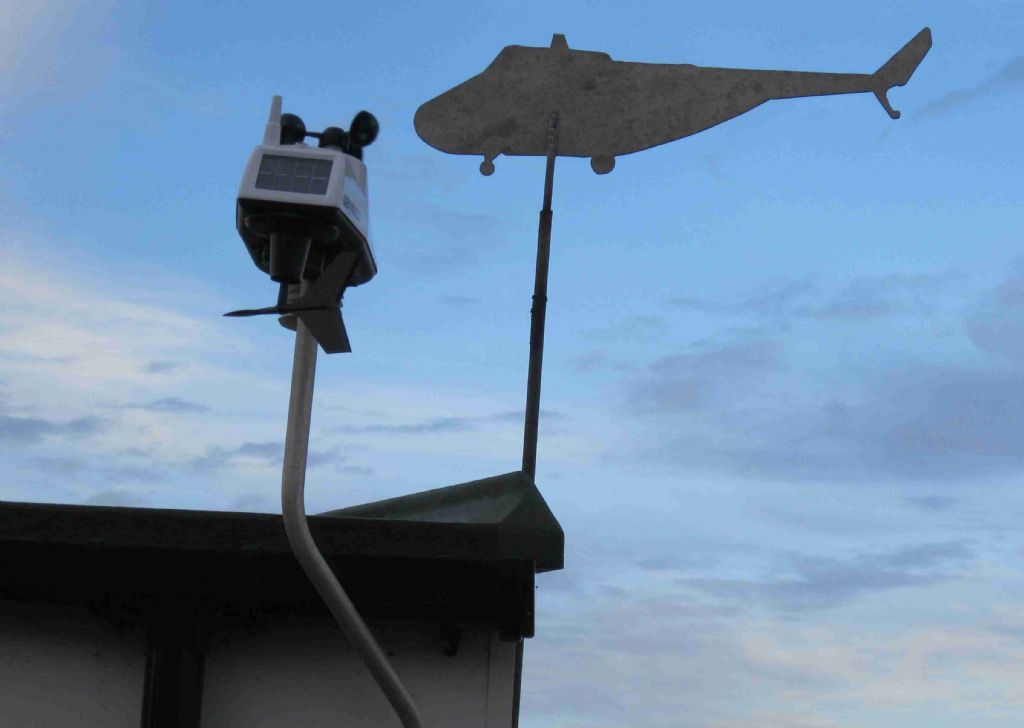
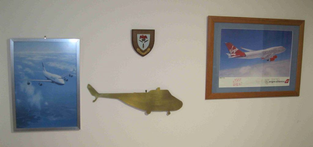
      Not exactly today, but have, at long last, finished the 'nostalgia indulgence' for the weather vane and the 'Office'. One in brass and one in aluminium. Happy days!!

      img_0013a.jpg

      img_0015a.jpg

      rgds

      Bill

      Advert
      #384380
      HOWARDT
      Participant
        @howardt

        Just a bad week. Broke the drive belt on the lathe, no stock and not standard so looked for alternatives, now waiting for new pulleys and belts, which will have to be modified to fit. Then left the band saw unattended while going through 110mm bar. The blade jammed and now in need of a new motor. Oh well that's two jobs for next week!

        #384383
        Gray62
        Participant
          @gray62

          quorn-2.jpg

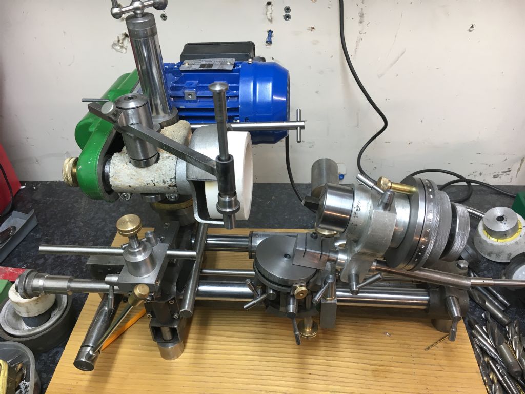
          Finally got around to a trial assembly of a much modified Quorn based on Mk2 castings. Still some work to do but the end is in sight. A trial grind on a few drills (4 facet) and HSS lathe tools showed promising results. Not quite got the right settings for the drill geometry so need a little more thought on that and maybe a setting jig for consistent results.

          Edited By Gray on 07/12/2018 16:35:14

          #384388
          Ron Laden
          Participant
            @ronladen17547
            Posted by Andrew Johnston on 07/12/2018 13:11:42:

            Posted by Ron Laden on 07/12/2018 08:03:51:

            Andrew, you know what the perfect vehicle would be..? a van based horse box. It wouldnt need to be a big one, say transit size. The long wheel base ones have a small living/sleeping area behind the front seats, plus you get plenty of space in the back and even a fold down ramp for driving the engine in and out, perfect.

            In one sense yes. But I don't really want the expense of running two vehicles. And to be honest I don't see myself doing much, if any, rallying so I wouldn't need overnight accommodation. If the worst did come to the worst I could sleep in an enclosed trailer. I spent a week sleeping in a glider trailer some years ago, after my tent decided it was no longer waterproof, so a trailer would be no hardship. smile

            Andrew

            Probably best anyway Andrew as you do realise that jodhpurs and riding boots are mandatory if you have a horsebox and I bet you cant see yourself in those..surprise

            #384400
            martin perman 1
            Participant
              @martinperman1

              I've spent many a happy night sleeping in the back of my works van, a good sleeping bag and double air bed was always comfortable.

              Martin P

              #384411
              Anonymous
                Posted by Ron Laden on 07/12/2018 17:07:57:

                Probably best anyway Andrew as you do realise that jodhpurs and riding boots are mandatory if you have a horsebox………..

                Definitely not my style; not into horses, or horsey types. I'd better not say where I think the best place for a horse is.

                Andrew

                #384412
                Anonymous
                  Posted by tractionengine42 on 07/12/2018 13:58:44:

                  Andrew, I'm using a 0.2mm/20 deg point carbide engraving cutter at 20k rpm.

                  That's interesting, thanks. I played with engraving cutters some years ago on my CNC mill, without much success, other than in breaking cutters. I came to the conclusion that the maximum 5000rpm simply wasn't high enough. I think I've still got some cutters, so now I have a high speed spindle attachment I should have another play.

                  Andrew

                  #384438
                  Phil Whitley
                  Participant
                    @philwhitley94135
                    Posted by Philip Rowe on 07/12/2018 11:55:01:

                    Posted by Phil Whitley on 06/12/2018 19:42:10:

                    Made a vibratory polisher for my daughter to polish her special stones with! the plastic container lifts off so that she can have different polishing medium in seperate bowls, thus avoiding the mess!
                    Phil

                    I'm intrigued, how is the vibration generated? Is it a simple eccentric weight on a motor driven shaft of some description? Also how do the plastic containers stand up to the ravages of the various polishing mediums?

                    Phil

                    Hi phil, Vibration comes from a large 12v ball bearing server fan with a bolt added to one of the fins, I started with a 2ba steel nut and bolt, and if that proves insuficcient, I will fit a larger one , as to your second question, the amswer is, we'll let you know, baptism of fire is this weekend!

                    Phil

                    Phil.

                    #384642
                    Perko7
                    Participant
                      @perko7

                      Worked on a single-wheel trailer to tow behind the pushbike, using an old bike frame with some tubes cut off and re-welded in different locations, and a long goose-neck to attach to a tow-point under the bike seat. Intent is to use it to carry gear on some overnight trips along various rail trails and other mountain-bike or horse trails in the region. All i need to do now is make a flexible coupling for the tow-point and work out how to attach it to the frame (oh, and get fit enough to ride the jolly thing again……).

                      #384651
                      John Hinkley
                      Participant
                        @johnhinkley26699

                        I'm impressed! Only one wheel – how do you keep it upright with a flexible coupling – with a gyroscope? Or is a VERY wide wheel like a lawn mower?

                        John

                        #384693
                        Ian S C
                        Participant
                          @iansc

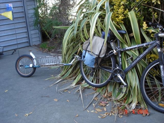
                          I use such a trailer most days, other times I use a two wheel trailer for heavier loads. Only got this photo at the moment, on this my old bike the draw bar on the bike is fixed, and the trailer pivots up and down, left and right at the hitch point about 100 mm behind the rear wheel. This system limits the load that can be carried before the front wheel starts to lift. The draw bar on the new (E) bike, The draw bar is pivoted as close as possible to the rear axle, and at the pivot point L & R is behind the rear of the wheel. The trailer in the photo took less than an hour to make, the 16" wheel from a kids size bike, bought for $NZ 5 at a garage sale, front forks pushed inside a piece of tube from the frame of a scrapped 10 speed bike, basket from a junked freezer. Get going with one of these, and you'll wonder why you didn't do ti sooner, and why are they not selling like hot cakes for next to nothing, made in China they could sell here for $NZ 20.

                          Ian S C

                          dsc01368 (640x480).jpg

                          #384703
                          martin perman 1
                          Participant
                            @martinperman1
                            Posted by Perko7 on 09/12/2018 03:51:08:

                            Worked on a single-wheel trailer to tow behind the pushbike, using an old bike frame with some tubes cut off and re-welded in different locations, and a long goose-neck to attach to a tow-point under the bike seat. Intent is to use it to carry gear on some overnight trips along various rail trails and other mountain-bike or horse trails in the region. All i need to do now is make a flexible coupling for the tow-point and work out how to attach it to the frame (oh, and get fit enough to ride the jolly thing again……).

                            Many moons ago my brother and I had paper rounds and our Father made us two wheeled trailers to pull behind our bikes, the swivel was an old caster with the wheel removed the towing arm was held in place where the wheel went with a bolt and the caster was bolted up under the seat,

                            Martin P

                            #384816
                            Perko7
                            Participant
                              @perko7

                              John, Ian S C describes it correctly, the trailer hitch only allows vertical (up and down) movement of the trailer along with left and right for turning. The geometry of the hitch point to the wheel contact point with the ground provides a level of stability if the weight is kept low down. Bit like towing a wheelbarrow in reverse.

                              Ian, mine uses a 'step-through' style frame with an extension welded to the steering tube to curve across the back wheel of the towing bike. I wanted to maintain the same wheel size as the towing bike so it gives me a spare tyre, wheel rim and spokes if anything major should happen to one of the bike wheels while out riding. I'll be fitting a basket or panniers of some sort on each side of the frame, as well as several water bottle holders.

                              I'll post some photos once it's presentable.

                              #384839
                              Ian S C
                              Participant
                                @iansc

                                Some designs put the hitch on the seat post, just below the seat, I did that for the lad across the road for his paper round. I don't like the common design that has a long sweeping tow bar that connects to the(usually) Lh end of the rear axle. My design is quite happy following behind on the local forest bike track, any where the bike will go the trailer will go.

                                For heavy weights, two wheels is the only way, mine has 16" wheels. I bought home in a number of loads all the 75 x 50, and 100 x 50 timber to build the partition between the car(Mum's) and my workshop, by fitting a turn table on the trailer, and strapping an extra pair of wheels on the end of the timber. It helps that I live in a small rural town, and also it is fairly flat.

                                Ian S C

                                #385195
                                Mark Rand
                                Participant
                                  @markrand96270

                                  After drilling and tapping the required holes, I did a trial assembly of the 7 5/8" raising block I'm making for the milling machine.

                                  Advantages:-

                                  1. It gives me enough headroom to do two of the jobs I've got lined up for the mill.
                                  2. It allows the full travel of the knee. (what's the point of a table that can be raised to the same height as the spindle nose?)

                                  Disadvantages:-

                                  1. I'm going to need duckboards or steps to change tools and speeds, since the mill is already as much as I'm comfortable reaching up to without the raising block.
                                  2. I don't know yet what, if any, effect there will be on rigidity. That'll be found out when I start to use it.
                                  3. As shown in the first picture, The raising block could have been even taller. There's another 5" of quill travel available!


                                  During the drilling of the holes, I hit a couple of hard spots that needed the drill to be resharpened. I stuck the drill in the Drill Doctor and ended up with variable (usually negative) relief several times. I've been having problems with the Drill Doctor 750X, even when following the instructions religiously, for some time. So the Drill Doctor has been struck off for gross incompetence and a Picador drill grinding jig was mounted on the surface grinder. Perfect results in a fraction of the time surprise. I had. previously, had reasonable results from the DD, but it gradually became unreliable even after replacing some of the wear parts at significant expense. Its now going to the local tip!


                                  The lugs on the side of the raising blocks are to take some arms/brackets to hold the milling vices and the rotary table and its chuck out of the way, but where I don't have to lift them onto the table when I need to change them.

                                  Edited By Mark Rand on 12/12/2018 00:01:59

                                  #385434
                                  Roderick Jenkins
                                  Participant
                                    @roderickjenkins93242

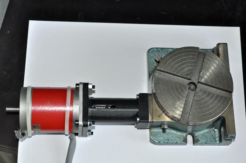
                                    I took advantage of ian p's advert on here for a Steve Ward Rotary controller to attach to my 4" Sharp rotary table.

                                    I'd really only intended this 3D printed connector as a prototype prior to fabricating something in steel but I think it might be robust enough to be a permanent fixture – we shall see!

                                    rotary table.jpg

                                    It all works really well. Ian, you clearly did a nice job of putting the controller together.

                                    Cheers,

                                    Rod

                                    #385469
                                    Ian P
                                    Participant
                                      @ianp

                                      Well that is a surprise, as I was not aware that I had advertised Steve Webb's controller, or anything else on here.

                                      JS (very much missed!) sold me one of his boards and a programmed ICs which I made up in a casing complete with and old laptop external PSU. The casing front and back were actually the discarded lids off two scrap ABS electrical enclosures (black rectangle on the front panel is the stepper driver heatsink).

                                      I think your printed motor mount is more than man enough for the job and a metal version would not perform any better. Is the slot purpose to give access to the coupling grubscrews?

                                      Ian P

                                      #385471
                                      Johnboy25
                                      Participant
                                        @johnboy25

                                        Rod… what material did you extrude on the 3D printer to make the extender/adapter for the stepper motor & rotary table?

                                        John

                                        #385481
                                        Roderick Jenkins
                                        Participant
                                          @roderickjenkins93242

                                          Whoops, sorry – Ian J not P. Bit of a coincidence though!

                                          The connector housing is PLA – I haven't investigated printing ABS yet. And yes, the slot is to get at the grubscrews on the flexi connector joining the 1/4" stepper shaft to the 3/8" rotary table shaft. The flexi connector was an Ebay purchase, 6.35mm to 8mm which I had to drill out to .375". The handle on the RT controls the worm engagement so I also had to make a collar with a locking screw to fit on the shaft inside the housing. That was the first engineering job in the new workshop smiley.

                                          Rod

                                          #385542
                                          mark costello 1
                                          Participant
                                            @markcostello1

                                            If You are getting negative rake with the Drill Doctor, just slightly loosen the collet and turn the drill bit slightly clockwise (I think) and tighten it up and try again. If it's worse then it goes the other way, I don't have My notes here with Me at the moment.

                                            #385558
                                            Mark Rand
                                            Participant
                                              @markrand96270
                                              Posted by mark costello 1 on 13/12/2018 21:57:49:

                                              If You are getting negative rake with the Drill Doctor, just slightly loosen the collet and turn the drill bit slightly clockwise (I think) and tighten it up and try again. If it's worse then it goes the other way, I don't have My notes here with Me at the moment.

                                              It should be anticlockwise for more relief, assuming the DD instructions about moving the collet clockwise for more relief are correct. Results were still inconsistent. I just got sick of the thing's problems, even though I've used if for five years.

                                              The Picador drill grinding fixture, mounted on the surface grinder really is an order of magnitude faster and more repeatable. I had been looking at Graham Meek's modifications, but most of them aren't needed for the Picador version. I will, probably, build a larger version to cope with MT drills up to 1" diameter.

                                              #385603
                                              Perko7
                                              Participant
                                                @perko7
                                                Posted by Perko7 on 10/12/2018 05:01:12:

                                                John, Ian S C describes it correctly, the trailer hitch only allows vertical (up and down) movement of the trailer along with left and right for turning. The geometry of the hitch point to the wheel contact point with the ground provides a level of stability if the weight is kept low down. Bit like towing a wheelbarrow in reverse.

                                                Ian, mine uses a 'step-through' style frame with an extension welded to the steering tube to curve across the back wheel of the towing bike. I wanted to maintain the same wheel size as the towing bike so it gives me a spare tyre, wheel rim and spokes if anything major should happen to one of the bike wheels while out riding. I'll be fitting a basket or panniers of some sort on each side of the frame, as well as several water bottle holders.

                                                I'll post some photos once it's presentable.

                                                Well, i've finished the trailer and hooked it up to the bike, but the performance was pretty underwhelming. Very unstable and leaning the opposite way when cornering. Seems like i've messed up the geometry of the tow hitch arrangement with the axis of the left/right pivot leaning the wrong way. Will need to remake the tow hitch, but even then i'm not sure it's going to work too well. I'll give it another shot next week but if it's no better then i'll put it in the 'lessons learnt' box. frown.

                                                #385633
                                                Ian S C
                                                Participant
                                                  @iansc

                                                  Perko 7, I must get some photos of my hitch, the hitch part on the trailer is 2" long with a 3/4" bore, the part on the bike is in two parts, one at the top, and the other at the bottom, ie double shear. through the three parts is a 3/4" dia pin(tube actually), head at the top, and a R pin through the pin at the bottom or the main pin tends to work it's way out. The set up must be ridged vertically. You should have no stability problems. You could try having the main beam of the trailer an inch or three lower than the axle height. My trailer with 16" wheels has 6 1/2" road clearance.

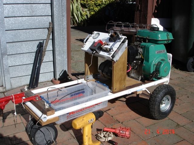
                                                  This is also towable, it is a home built alternator with a 3hp Kawasaki motor, mounted on a home built sack barrow. when hitched up the wheels at the Lh end are removed. Total cost $NZ10 for the motor, $NZ26 for the main wheels.

                                                  Ian S C

                                                  dsc00844 (640x480).jpg

                                                  #385821
                                                  Colin Heseltine
                                                  Participant
                                                    @colinheseltine48622

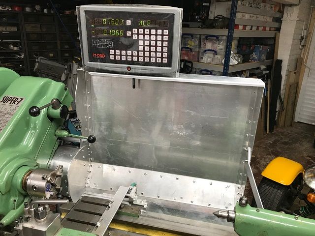
                                                    In between trying to get the Chester mill motor off I have been making up a backsplash guard for the Myford Super 7.

                                                    Needs a bit more work to route the DRO cables and provide safe power to the DRO but basically finished it today. Fitted the DRO scales about 12 months ago and this is the first time I have powered them on. The display came of the Myford 7 I recently sold.

                                                    I need to fit the DRO modification to put the magnetic scale under the cross-slide but need the mill to do this or get my mate to do it on his Hauser jig borer.

                                                    Colin

                                                    backsplashresize.jpg

                                                    #386008
                                                    Neil Wyatt
                                                    Moderator
                                                      @neilwyatt

                                                      Well I boxed a 12V 4A transformer and fiutted some connectors to restore our 'fibre optic Christmas Tree' to its former glory, having reached the end of my pine-needle tether.

                                                      Then my battery powered lights (lights still working after three Christmases!) had three wires cut through so a bit of experimentation needed.

                                                    Viewing 25 posts - 1,776 through 1,800 (of 1,832 total)
                                                    • Please log in to reply to this topic. Registering is free and easy using the links on the menu at the top of this page.

                                                    Advert

                                                    Latest Replies

                                                    Home Forums The Tea Room Topics

                                                    Viewing 25 topics - 1 through 25 (of 25 total)
                                                    Viewing 25 topics - 1 through 25 (of 25 total)

                                                    View full reply list.

                                                    Advert

                                                    Newsletter Sign-up