VFD Question

Advert

VFD Question

Home Forums General Questions VFD Question

Viewing 25 posts - 1 through 25 (of 124 total)
  • Author
    Posts
  • #445225
    Gerard O’Toole
    Participant
      @gerardotoole60348

      I am a little confused about VFD's 3-phase motors and setting. Reading her on the forum and also on other websites is only adding to my confusion I am afraid. I should add that i have a mill working on a VFD but I am a little concerned about some of the settings. In particular I am confused about reference to dual voltage etc.

      As I understand it, two measurements of voltage are often quoted , that for a single phase, eg. 230V and that value between any two phases which I understand, from various books etc. to be fixed at single phase voltage *√3 ( square root of 3) or 1.732 . So a single phase at 220V provides 380V between any two phases , 230V provides 400V and 240V will provide 415V between any two phases. These are the old European standard, the new EU standard and the UK standard respectively.

      My VFD provides three phases at up to 240V. My understanding therefore is that as these phases are staggered at 120 degrees the same rule , i.e. if the single phase voltage is set at 240V then the between voltage is automatically 415V.

      Perhaps my reasoning above is faulty. Please let me know, i have no experience or expertise in electrical matters and i might be misunderstanding the matter.

      Now I see on this forum people say that you cannot power a 380V motor( or 400V or 415V) from a 240V VFD. But it seems to me that a 240V VFD exactly matches 415V across any two phases and should work correctly.

      Now to my own setup. I was advised, based on the last paragraph, that i need to reduce the frequency proportionally to the voltage in order for the VFD to work. I.e. 400/240 = 1.71 so reduce the frequency 50Hz/1.71 = 29.2Hz. But this seems wrong to me as it is mixing up the single phase and between phase voltages.

      I might add that I have made this adjustment, i.e. I have set the maximum frequency to 29Hz and the motor does work, although at a slower speed that it is designed for.

      i wonder can someone please explain it all to me, preferable in simple terms I might understand.

      Thanks for reading this far.

      Advert
      #27053
      Gerard O’Toole
      Participant
        @gerardotoole60348

        3 phase voltages and setup for VFD

        #445231
        not done it yet
        Participant
          @notdoneityet

          The basics of a VFD is to vary the frequency – it’s in the name. The frequency determines the motor speed. If the motor is rated at 50Hz, it will run (at normal UK mains frequency) at its rated speed. Reducing the frequency simply changes the motor speed downwards.

          Most VFDs also attempt to improve the torque at lower motor speeds as the power available would normally be related to the lower speed and torque is a function of rotational speed and power.

          Set your frequency to whatever you require, within reason – remembering the design was for 50Hz. At lower speeds there will be less cooling which is likely to become more important when drawing the maximum power – the motor may overheat. At higher frequencies the motor will consume more power with its cooling fan and one must consider the physical constraints of the design – bearings, for instance, particularly the type of bearing. Ball and roller bearings will withstand higher speeds better than plain bearings.

          #445232
          Anonymous

            The 240V output from the VFD is phase to phase, not phase to neutral.

            You can run a 415V motor on a 240V output VFD, but the torque, and hence power, will be reduced in proportion. If the 415V motor is designed to run in star (most are) then by changing the arrangement to delta you can run from 240V without loss of power. Many motors have links in the connection box that make it easy to change from star to delta.

            You don't need to change the frequency to make the VFD work. What your adviser may have been saying is that the output voltage needs to reduce as the frequency reduces. Otherwise you will overcurrent, and overheat, the motor. It's called a v/f curve, and is looked after by the VFD, not something the user needs to alter.

            Andrew

            #445233
            daveb
            Participant
              @daveb17630

              Most of the low cost inverters output 220/240v 3 phase. A 415v 3 phase motor needs to have the windings connected in Delta to operate with these. If the windings are Star connected, they are effectively in series. There are 220v in/415v out inverters available but they are expensive, it is cheaper to reconfigure the motor windings.

              #445234
              John Olsen
              Participant
                @johnolsen79199

                Hi Gerard,

                The usual VFD can only provide a maximum phase to phase voltage the same as the input AC Voltage. So it will run a delta connected 240 Volt motor at full power. The same motor if Star connected would run off the usual 415 V supply. This supply would provide 240 Volts between phase and neutral. Most motors come star connected for 415, and it is usual to have to restrap them to delta connected to run off a VFD, at least the type of VFD that is designed for 240V input. (There are VFD's that will take three phase input, these are not usually of much interest to amateurs since we usually don't have three phase power.)

                There are VFDs that will take a 240V supply and provide the correct output for a 415 V star connected motor, probably by using a voltage doubling rectifier. I have no experience with these, but they have been on the market for a while, so presumably work OK.

                Incidently you can run a motor on a lower voltage than the plate rating when necessary. I have a shaper with a Delta connected 460 Volt motor. This makes it impossible to lower the voltage rating, since if I star connected it the required Voltage would go up, to over 600 Volts. But it actually runs fine from a VFD , even the the voltage is effectively half what it should be. This limits the maximum power to about half the nameplate rating too, but since it is a three horsepower motor, half that will shift metal quite fast enough for most purpose.

                So normal 3 phase is 240 phase to neutral, 415 phase to phase, but the three phase from a VFD is 240V phase to phase, and there is no neutral. (The neutral from the incoming mains is not a neutral for the output side.)

                John

                #445236
                Michael Gilligan
                Participant
                  @michaelgilligan61133
                  Posted by Gerard O'Toole on 08/01/2020 09:46:23:

                  […]

                  Now to my own setup. I was advised, based on the last paragraph, that i need to reduce the frequency proportionally to the voltage in order for the VFD to work. I.e. 400/240 = 1.71 so reduce the frequency 50Hz/1.71 = 29.2Hz. But this seems wrong to me as it is mixing up the single phase and between phase voltages.

                  I might add that I have made this adjustment, i.e. I have set the maximum frequency to 29Hz and the motor does work, although at a slower speed that it is designed for.

                  i wonder can someone please explain it all to me, preferable in simple terms I might understand.

                  Thanks for reading this far.

                  .

                  You will find a good explanation of the 29Hz linked on this previous thread:

                  **LINK**

                  https://www.model-engineer.co.uk/forums/postings.asp?th=97755

                  MichaelG.

                  #445239
                  Gerard O’Toole
                  Participant
                    @gerardotoole60348

                    Thanks for all the replies.

                    My motor is wired delta.

                    The VFD ( Bosch) states that the output is 3x 240V. I take that to mean three phases at 240V. By definition the between phase voltage is therefore 415V if each phase is 240V.

                    I will try reading up more on the difference. The manual states that the usual setting for maximum frequency is 50Hz. My concern is that I am being advised to set this to 29Hz.

                    I might try measuring the voltages with a meter and see what readings I get.

                    Thanks to you all for taking the time to read and reply, much appreciated

                    #445241
                    SillyOldDuffer
                    Moderator
                      @sillyoldduffer

                      Don't overthink it, is my advice! The motor is the place to start.

                      Your description of 3-phase is good, but how it's wired up can vary.

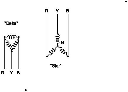
                      Inside a three-phase motor are three windings. They can be connected in two different ways, 'star' and 'delta':

                      stardelta1.jpg

                      When a motor is wired 'delta', each winding is connected directly across a phase. Wired 'star' two windings are wired across each phase, ie twice the resistance.

                      So a motor wired 'delta' runs off 230V 3-phase, while exactly the same motor wired 'star' needs 440V 3-phase.

                      Investigate your motor plate and perhaps the terminal box. Most, but not all 3-phase motors, bring the windings out to terminals. If so, the motor can be easily wired to run on either 440v or 230. It is possible to get high-voltage VFDs, but yours is probably the low voltage type intended for running a delta wired motor. Unfortunately not all motors bring the windings out, in which case it's necessary to dig around inside the motor to find and open the star point marked 'N'.

                      If you connect a motor in star (440v) to a delta inverter (220v), the motor may well run, but only at much reduced power. Reconfigure the motor to delta, and all should be well.

                      Using the VFD to change frequency provides speed control, rather than power. RPM is related to the number of poles in the motor and supply frequency. If the VFD is set to 50Hz, it will spin the motor at normal rpm. Increasing the frequency (don't go mad!) will over-speed it, while decreasing frequency will slow it down. Don't run the motor at slow speed for a long time because it might over-heat. (The motors fitted to machines designed for VFD control are usually fitted with a separate full-speed cooling fan. Older machines, designed to run at constant speed, may rely on an impeller directly attached to the motor to keep cool; impellers don't work at low speeds.) But, to get everything working just set the VFD to 50Hz and don't worry about "i need to reduce the frequency proportionally to the voltage in order for the VFD to work. I.e. 400/240 = 1.71 so reduce the frequency 50Hz/1.71 = 29.2Hz."

                      There are several chaps smarter and more experienced in 3-phase than me on the forum: worth waiting to see what they say!

                      Dave

                      Edited By SillyOldDuffer on 08/01/2020 10:45:21

                      #445250
                      Anonymous
                        Posted by Michael Gilligan on 08/01/2020 10:27:53:

                        You will find a good explanation of the 29Hz linked on this previous thread:

                        **LINK**

                        I've re-read it and am still none the wiser as to what he's trying to say. sad

                        Andrew

                        #445251
                        Michael Gilligan
                        Participant
                          @michaelgilligan61133
                          Posted by Andrew Johnston on 08/01/2020 11:26:20:

                          Posted by Michael Gilligan on 08/01/2020 10:27:53:

                          You will find a good explanation of the 29Hz linked on this previous thread:

                          **LINK**

                          I've re-read it and am still none the wiser as to what he's trying to say. sad

                          Andrew

                          .

                          Then evidently it is not a good explanation.

                          MichaelG.

                          #445268
                          John Haine
                          Participant
                            @johnhaine32865

                            Talking nonsense IMHO.

                            #445270
                            Gerard O’Toole
                            Participant
                              @gerardotoole60348

                              Thanks everyone.

                              I did manage to measure the between voltage and it measured 220V not 380V

                              I wil leave everything alone , as the motor is working fine and I don't run the mill for long periods of time. The motor never gets hot, at most a comfortable warm after a good few hours.

                              The motor is definitely wired delta, I did that before fitting the VFD. ( Originally it could be switched from Star to Delta)

                              It is the original German motor fitted to a Deckel FP1 mill from 1950's I think.

                              thanks again for all thetrouble you have all taken to explain things to me

                              #445285
                              norm norton
                              Participant
                                @normnorton75434

                                I thought I had a limited understanding of this, but now I am confused.

                                If a residential road is fed with three separate phases of 240v, then each house takes a feed from one of those phases and has single phase 240v. If an industrial premise takes all three phases then (I assumed) it has an available feed of 415v (or 380v or whatever) 3 phase. Correct or wrong?

                                Or are there transformers on the old poles to drop 415v lines down to 240v domestic?

                                Now if you take one of the 250v phases, and put it through a VFD box, is the output actually three separate 250v sine waves each shifted by one-third of a cycle. If so, why is this phase adjusted supply not producing 415/380v 3 phase?

                                I need to see the actual AC diagrams perhaps of the two 3 phase scenarios I have described. I think Gerard was asking the same question.

                                Norm

                                #445292
                                Martin Connelly
                                Participant
                                  @martinconnelly55370

                                  3 phase voltages csn be given as phase to phase or phase to neutral. UK mains is 230v phase to neutral and 398v phase to phase. The output of a vfd connected to 230v phase to neutral is 230v phase to phase. As there is not usually a neutral from the vfd they do not give the phase to neutral voltage but it would be 133v if it was measurable. If you really want to measure it connect it to a motor wired as star and measure the star point to phase voltage. It should be 133v. Voltages are approximate.

                                  Martin C

                                  #445293
                                  Gerard O’Toole
                                  Participant
                                    @gerardotoole60348
                                    Posted by norm norton on 08/01/2020 14:20:39:

                                    I thought I had a limited understanding of this, but now I am confused.

                                    If a residential road is fed with three separate phases of 240v, then each house takes a feed from one of those phases and has single phase 240v. If an industrial premise takes all three phases then (I assumed) it has an available feed of 415v (or 380v or whatever) 3 phase. Correct or wrong?

                                    Or are there transformers on the old poles to drop 415v lines down to 240v domestic?

                                    Now if you take one of the 250v phases, and put it through a VFD box, is the output actually three separate 250v sine waves each shifted by one-third of a cycle. If so, why is this phase adjusted supply not producing 415/380v 3 phase?

                                    I need to see the actual AC diagrams perhaps of the two 3 phase scenarios I have described. I think Gerard was asking the same question.

                                    Norm

                                    Yes Norm

                                    I was asking the same question you asked. I too understood 3 separate phases at 240 V but apparently not

                                    gerard

                                    #445296
                                    Anonymous

                                      In the UK electricity distribution is 3-phase and earth, no neutral. At the local sub-station transformer the primary is wired delta and the secondary is wired star. So the secondary has a 'neutral' point. This is grounded at the sub-station. The cable running down the road has three phases, the neutral (aka earth at the sub-station) and a protective earth. The sub-station transformer is arranged so that the voltage from any phase to 'neutral' is 240V, while the voltage phase to phase is 415V, ie, times the square root of 3. So a property on single phase will have an earth, neutral and live (from one of the three phases). An industrial property will have the three phases and earth. A neutral may also be supplied for any single phase loads. That's what I have at home; three phases (which are fused) a neutral (which isn't fused) and an earth. I run the house off one phase and the neutral whereas the workshop runs from 3-phase. The neutral also runs around the workshop, but none of my machine tools use it. They just take 3-phases and earth. Remember that all quoted voltages are rms aka root-mean-square.

                                      I feel the need to go and machine a large lump of steel! If no-one has explained why a 240V in VFD cannot normally produce a 415V output by the time get back then I'll explain.

                                      Andrew

                                      #445299
                                      Anonymous

                                        Should have mentioned that the reason the phase to phase voltages are higher is because the phases are time shifted with respect to each other by 120 degrees.

                                        Andrew

                                        #445308
                                        norm norton
                                        Participant
                                          @normnorton75434

                                          Ahh.. Thank you Martin and Andrew – got that.

                                          So I (and perhaps two others in the world) have been misunderstanding the output from the workshop VFDs that we use. It is 240v phase-to-phase, and if there was a neutral it would be about 133v on each phase to neutral.

                                          I guess the rules of physics say that one cannot phase shift 240v AC by 120 degrees and again by another 120 degrees, otherwise we would get 415v quite easily.

                                          Norm

                                          #445311
                                          John Haine
                                          Participant
                                            @johnhaine32865

                                            To save Andrew doing it. It a simple VFD the mains is full-wave rectified and charges a big capacitor up to 230 x sqrt2 = 325 V. It then has 3 high-voltage push-pull output stages run off this voltage to drive the 3 outputs. Each one is driven by a variable mark/space PWM signal at perhaps a few kHz. At 50:50 m/s the effective average output of one of these is 162.5 V, and it can be varied down to 0 V and up to 325 V. In effect this is +/- 162.5 V relative to an average of zero. If you vary the m/s ratio in a sinusoidal manner with time at 50 Hz you can generate what appears to a motor as a 50 Hz sine wave with a peak voltage of 162.5 V.

                                            Now there are 3 output stages and they are driven to generate waveforms 120 degrees out of phase. If you connect a motor winding between two of these outputs it sees a voltage of 162.5 x sqrt(3) = 281 V peak or 199 V rms. This is not too much lower than the winding would see if it was connected between a line and neutral of a standard 3 phase supply so it will run with nearly the same current and power as normal.

                                            You can also play games where the waveform is not sinusoidal but the peak is "flatter", which will increase the rms voltage and current to compensate for the lower peak voltage. There's nothing particularly sacrosanct about sine waves.

                                            #445312
                                            John Haine
                                            Participant
                                              @johnhaine32865
                                              Posted by norm norton on 08/01/2020 15:52:14:

                                              Ahh.. Thank you Martin and Andrew – got that.

                                              So I (and perhaps two others in the world) have been misunderstanding the output from the workshop VFDs that we use. It is 240v phase-to-phase, and if there was a neutral it would be about 133v on each phase to neutral.

                                              I guess the rules of physics say that one cannot phase shift 240v AC by 120 degrees and again by another 120 degrees, otherwise we would get 415v quite easily.

                                              Norm

                                              You can shift it using a resistor-capacitor circuit, but inefficiently (because of the resistors). To get high efficiency you need at least two power feeds with a phase difference. There's something for example called a Scott transformer that will generate two phases at 90 degrees given a 3 phase supply, or vice-versa.

                                              #445316
                                              SillyOldDuffer
                                              Moderator
                                                @sillyoldduffer
                                                Posted by norm norton on 08/01/2020 14:20:39:

                                                I thought I had a limited understanding of this, but now I am confused.

                                                If a residential road is fed with three separate phases of 240v, then each house takes a feed from one of those phases and has single phase 240v. If an industrial premise takes all three phases then (I assumed) it has an available feed of 415v (or 380v or whatever) 3 phase. Correct or wrong?

                                                Or are there transformers on the old poles to drop 415v lines down to 240v domestic?

                                                Now if you take one of the 250v phases, and put it through a VFD box, is the output actually three separate 250v sine waves each shifted by one-third of a cycle. If so, why is this phase adjusted supply not producing 415/380v 3 phase?

                                                I need to see the actual AC diagrams perhaps of the two 3 phase scenarios I have described. I think Gerard was asking the same question.

                                                Norm

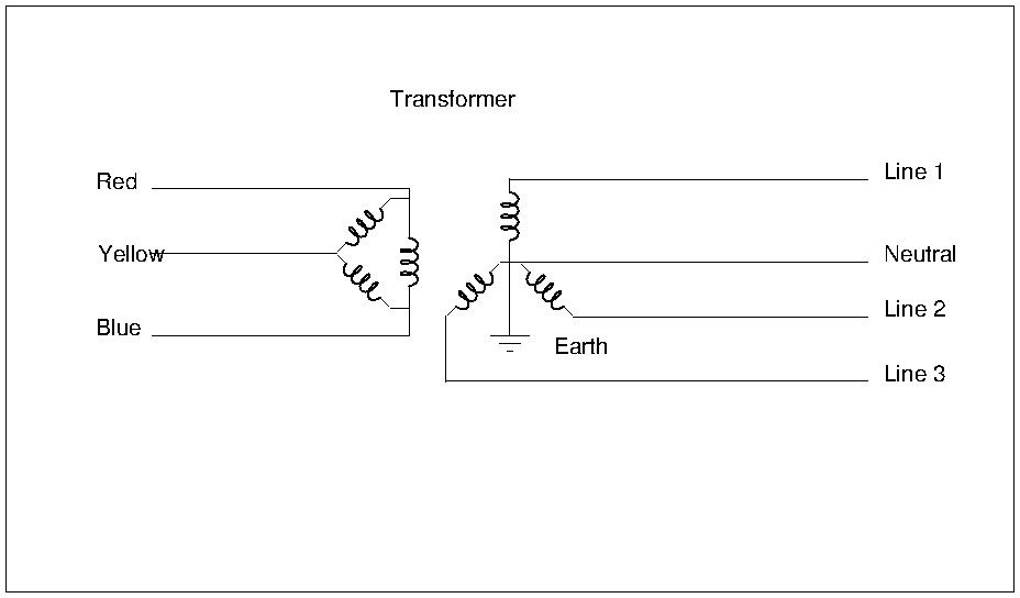
                                                Wonder if this helps.

                                                stardelta.jpg

                                                The diagram is typical of a UK sub-station transformer wired to supply a mix of single and three-phase consumers.

                                                Electricity from the power station arrives at high voltage on 3 wires and is connected to the input side of a 3-phase transformer wired in delta. Using 3 wires to transfer power at high voltage reduces resistive losses and hence the size of the wires needed. Unfortunately, 3-phase at high voltage is dangerous and inconvenient for most domestic purposes: imagine the circuit needed to switch a 3-phase light bulb on and off! On the other hand, industry needs 3-phase for big motors, electric furnaces and other heavy equipment.

                                                Fortunately, both single and three phase can be produced by wiring the output side of the transformer in star (aka 'Y&#39, and making the centre point made available as 'neutral'. Note the consumer side of the transformer has 4-wires, plus – not shown – some kind of earth safety as well.

                                                The voltage between Lines is 440v 3-phase. The voltage between any Line and Neutral is 230V single phase. In a factory, the system might be used to supply 3-phase to equipment and also single phase to domestic services like lighting. Care is taken to ensure 'Live' from different phases is kept well apart in the same building.

                                                Houses are connected in groups to different phases of the same supply. Be careful borrowing power from a neighbour – there's a slight risk his house might be on a different phase! Trying to buy a 3-phase supply for a home workshop meets with mixed results because the convenient availability of all three phases depends entirely on local details. My village has 3-phases and neutral on overhead wiring in the street outside: easy! Not everyone is so lucky – in suburbia, they might to dig a long trench back to the substation.

                                                Has to be said 3-phase electricity is the work of geniuses! Not obvious how it works, or that it neatly solves several different awkward supply problems. For example the system is self-balancing, ie able to cope with one phase being lightly loaded whilst the other two are working flat-out. Clever stuff squared!

                                                Dave

                                                #445374
                                                old mart
                                                Participant
                                                  @oldmart

                                                  I am using a VFD with a 1hp motor taking advantage of the speed control. I have set the frequency to vary between 25 and 75 Hz. I feel that going lower than 25 Hz is not suitable for my requirements, because at that frequency, the motor speed is halved from the standard 50 Hz, but the power is also halved. Below 25 Hz the drop off of power is rapid.

                                                  #445385
                                                  John Haine
                                                  Participant
                                                    @johnhaine32865

                                                    I regularly use the VFD on my mill at 10 Hz and below for power tapping. Though the power may be low there's plenty of torque. In fact you can drive an induction motor at very low speed or even zero speed and get full torque using a vector drive. Power not necessarily a good indication of usefulness.

                                                    #445386
                                                    John Haine
                                                    Participant
                                                      @johnhaine32865

                                                      I regularly use the VFD on my mill at 10 Hz and below for power tapping. Though the power may be low there's plenty of torque. In fact you can drive an induction motor at very low speed or even zero speed and get full torque using a vector drive. Power not necessarily a good indication of usefulness.

                                                    Viewing 25 posts - 1 through 25 (of 124 total)
                                                    • Please log in to reply to this topic. Registering is free and easy using the links on the menu at the top of this page.

                                                    Advert

                                                    Latest Replies

                                                    Home Forums General Questions Topics

                                                    Viewing 25 topics - 1 through 25 (of 25 total)
                                                    Viewing 25 topics - 1 through 25 (of 25 total)

                                                    View full reply list.

                                                    Advert

                                                    Newsletter Sign-up