Posted by SillyOldDuffer on 12/05/2019 11:55:31:
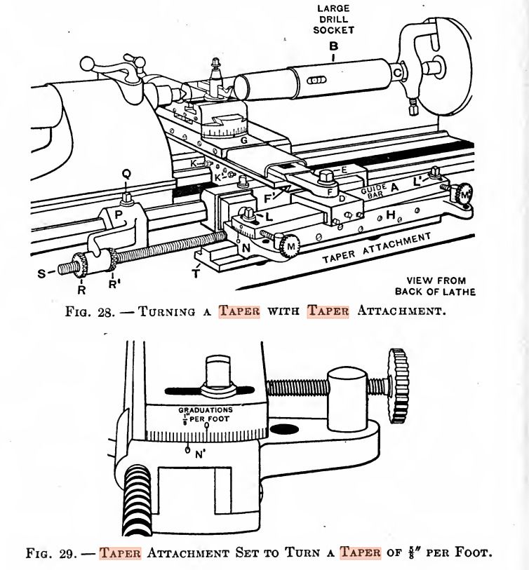
Alan's query made me realise I don't know how taper attachments work. There's a picture of one in this book, not quite what I expected:

Fig 29 shows the attachment is graduated in ⅛ inch over 1 foot, which is unfriendly!
What I was expecting (having glanced at one at an exhibition) was a rod connected between two scales behind the saddle and fixed to the bed such that traversing the saddle moved the cross-slide. Memory very untrustworthy but I think the scales were in degrees, total or included I know not.
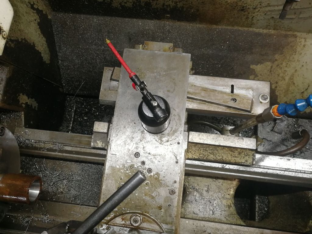
Conclusion: more than one type of taper attachment, and setting them up could be in degrees or as a length ratio, other than the obvious tangent. Be good to see a photo of Alan's attachment, I'd learn something!
Dave
You have it right, your description matches the pic you posted. Guide bar A is adjustable to the angle as marked on the end scale. Small saddle D traverses up and down it as the main lathe carriage moves along the main bed. Link F transfers the angular motion to the cross slide, which is free to move because the cross feed screw has been disconnected from the feed nut.
The whole taper unit in your pic is a bit more complex than on say a Myford as it has the ability to be slid up and and down the main bed and clamped in position to turn tapers at different distances from the headstock, but principal remains the same.
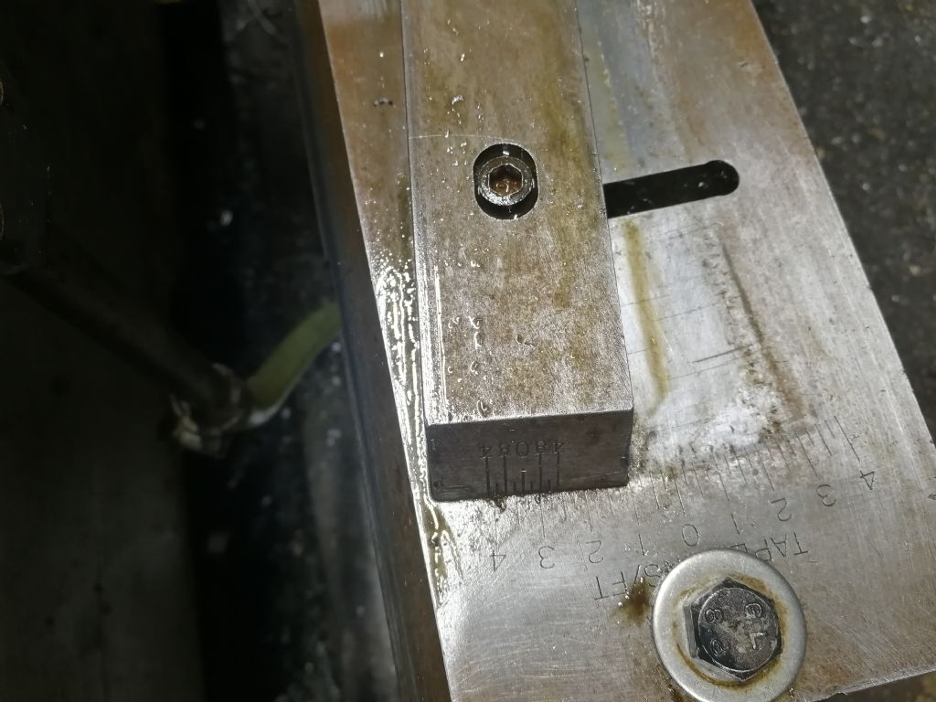
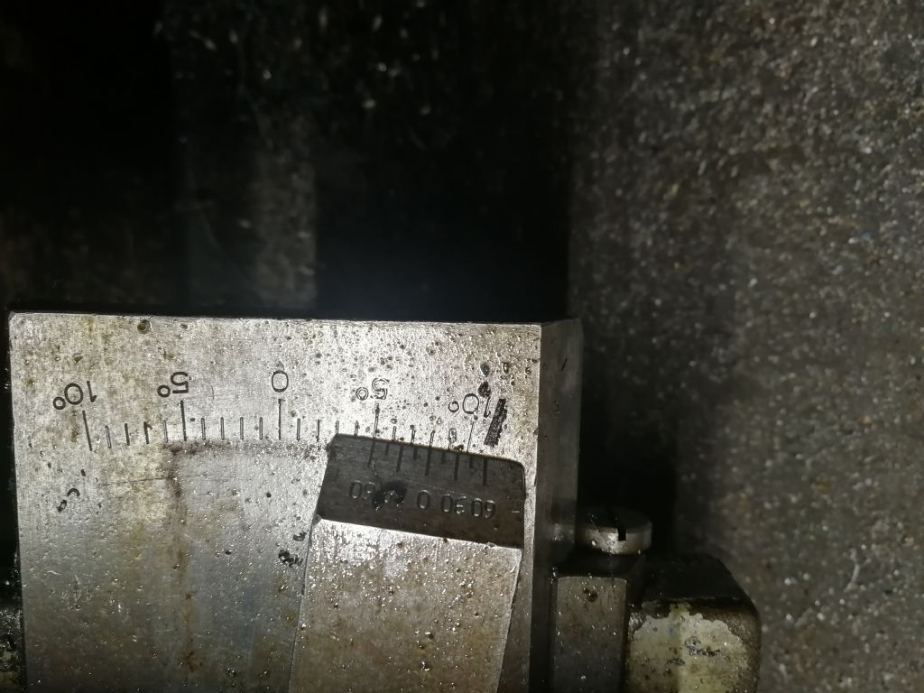
It would help to know what kind of lathe is in the OP and pics of teh set up would help. Some use degrees, others taper per foot on the end scale. And some refer to total included angle of the resulting turned taper, others to half that amount, ie the actual angle or offset of the guide bar itself. Varies from make to make.
ONe thing common to all is that the end scale is just a starting point guide, Final setting is almost always arrived at by trial and error cutting and measuring, or setting a known parallel bar between centres and reading off a dial indicator to get desired amount of infeed per inch or number or inches. Final fit can be by using a master taper – eg morse adaptor sleeve etc — and light bearing blue or even lead pencil marks to get a reading how they match up.
Edited By Hopper on 12/05/2019 13:05:58
ega.


