Tangential Tool Holder

Advert

Tangential Tool Holder

Home Forums Workshop Tools and Tooling Tangential Tool Holder

Viewing 16 posts - 51 through 66 (of 66 total)
  • Author
    Posts
  • #479006
    Jouke van der Veen
    Participant
      @joukevanderveen72935

      Yes, thank you!

      In your video WP20150916004 you make a deep cut and feed in the radial direction. That is what I meant.
      Now it is clear for me and I understand now that you should not cut deeper than half the diameter. This way of cutting should work for machining the tooth shape on a mill cutter for clocks wheels. There are people who use a tangential tool that cuts with two toolbits cutting the tooth shape in one step.

      Edited By Jouke van der Veen on 10/06/2020 21:37:10

      Advert
      #479043
      DiogenesII
      Participant
        @diogenesii
        Posted by Niels Abildgaard on 10/06/2020 08:24:20:

        Carborundum or silizium Carbide is much harder than aluminium oxide or corund that do not touch Tungsten Carbide .

        Ebay also mention bands with Zirkonia as abrassive.

        Is that hard enough to grind TungstenCarbide?

        ..Just been out for a definitive answer – I ground flats on the end of an old insert on my linisher – Zirconia will only just cut it (more like polishing, rather than shaping) and slow going, with heavy pressure (= belt wear) – I changed the belt to Silicon Carbide and removed more than twice as much material in c.25% of the time, with only light pressure. So No, not a practical proposition..

        Any one know a source for Silicon Carbide Tape?

        ..I'd never realised that my neighbours were interested in Engineering Experiments, but when I finished at 7am, they all were at their windows, cheering me on and punching the air in excitement. ..Gratifying.

        #479048
        Jouke van der Veen
        Participant
          @joukevanderveen72935

          In the Netherlands we have the expression: “A good neighbour is better than a far friend”.

          #479087
          Howard Lewis
          Participant
            @howardlewis46836

            IF it needs clarification, with a round toolbit, feeding radially should produce a groove width equal in diameter to that of the toolbit.

            There is little point in setting a depth of cut greater than half the diameter of the toolbit (which would be pretty deep, even with a 3 mm or 1/8 inch toolbit ) and then feeding axially, unless you wish to produce an annular groove, on a face. This would be a means of making a groove to take an 'O' ring to seal the face.

            Today, I hope to use a 1/8 inch diameter toolbit to cut a semi circular form thread, with a total infeed of 0.625 inches, but in a series of smaller cuts.

            The infeed will produce the thread form, and the axial feed, from the Leadscrew, will produce the helix which is the thread.

            HTH

            Howard

            #479127
            Jouke van der Veen
            Participant
              @joukevanderveen72935

              When I looked the video of Niels it got quite clear to me want he meant with depth of cut and axial and/or radial feed.

              For making a mill cutter for a clock wheel you also do not have to go deeper than half the diameter of the toolbit.

              An O-ring with a circular cross section used for vacuum applications is normally put in a rectangular or square groove. It is pressed into a more or less square cross section to close the connection. There are norms/specifications for combinations of groove dimension and O-ring cross section. Closing an O-ring in a round groove would give an undefined deformation of its cross section because where should the surplus of rubber flow when it is pressed together?

              #479143
              DiogenesII
              Participant
                @diogenesii
                Posted by Howard Lewis on 11/06/2020 12:44:04:

                …Today I hope to cut a semi circular form thread, with a total infeed of 0.625 inchess…

                HTH

                Howard

                ..Heavens above – that's some screw.. ..are you making a cider press? smile p

                #480803
                DiogenesII
                Participant
                  @diogenesii

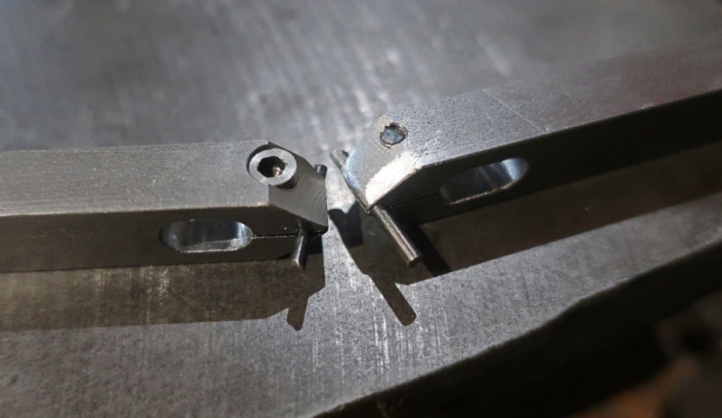
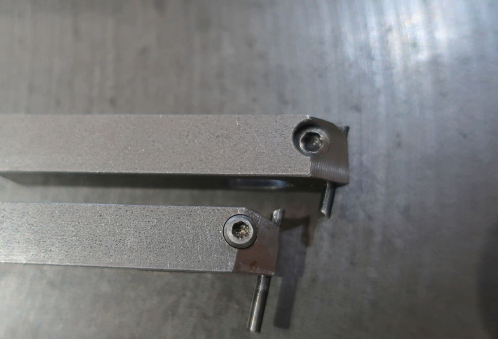
                  Following a week (and more) out of the workshop, I've finished a second toolholder.

                  Having digested the information provided in Niels' links and following a little correspondence, comment (thank you) and thought, the new version features a small but worthwhile adjustment to the tool angle, improved side clearance, and stronger tool-bit clamping.
                  I also bought a couple of 2mm round "Tivoly" carbide toolbits.

                  One of the first revisions was to amend the angle of the toolbit – in the original, I'd been fairly cavalier in the set-up and ended up with an angle of slightly less than the 12 degrees I'd shot for, so with this holder I was careful to err on the generous side to gain myself a little more side clearance.

                  The upper surface of the tool is machined to centre-height – this makes setting tool height easy, as the holder only needs to be inverted on a flat surface and the tool tip set to touch, whilst the clamp is tightened.
                  Currently, the tool is ground at the same angle to that in which it is inclined, to give a neutral rake that sits flat on the plate whilst setting – this means that the correct orientation of the tool can be both seen and felt during setting.

                  The nose of the new holder has an included angle of 80 degrees – reduced from the 85 used on the first tool, it makes acquiring the clearances for facing/turning less critical, and reduces the need to create extra easement by additional hand-filing of the nose.

                  The "flanks" of the nose were machined with the holder clamped horizontally – on my prototype, I machined them in the same "inclined-at-12-degrees" set-up as drilling for the toolbit, which looked neat & purposeful, but resulted in rather thin jaws, and I think the extra metal in the later version is a positive improvement – It also simplifies the making, as it requires only a simple (rather than a compound) angle to be made. I used a home-made 40 degree angle gauge cut from a piece of 6mm flat bar to align the holder on it's side in the mill vise.

                  The clamp screw size was upped to M4, the cap head being modified to provide clearance along the flank of the holder.

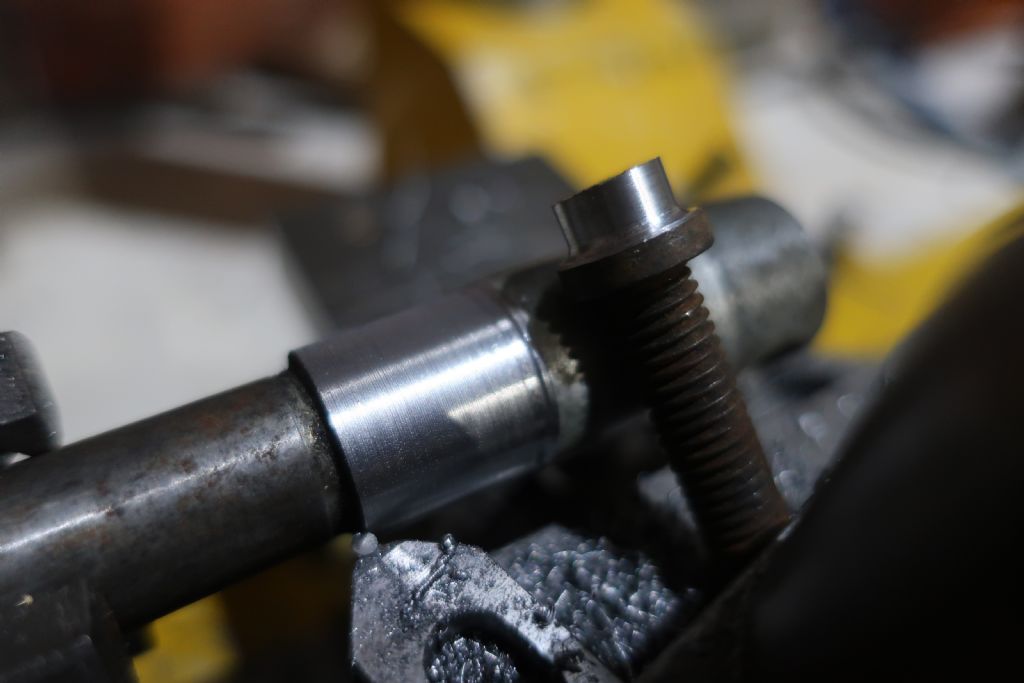
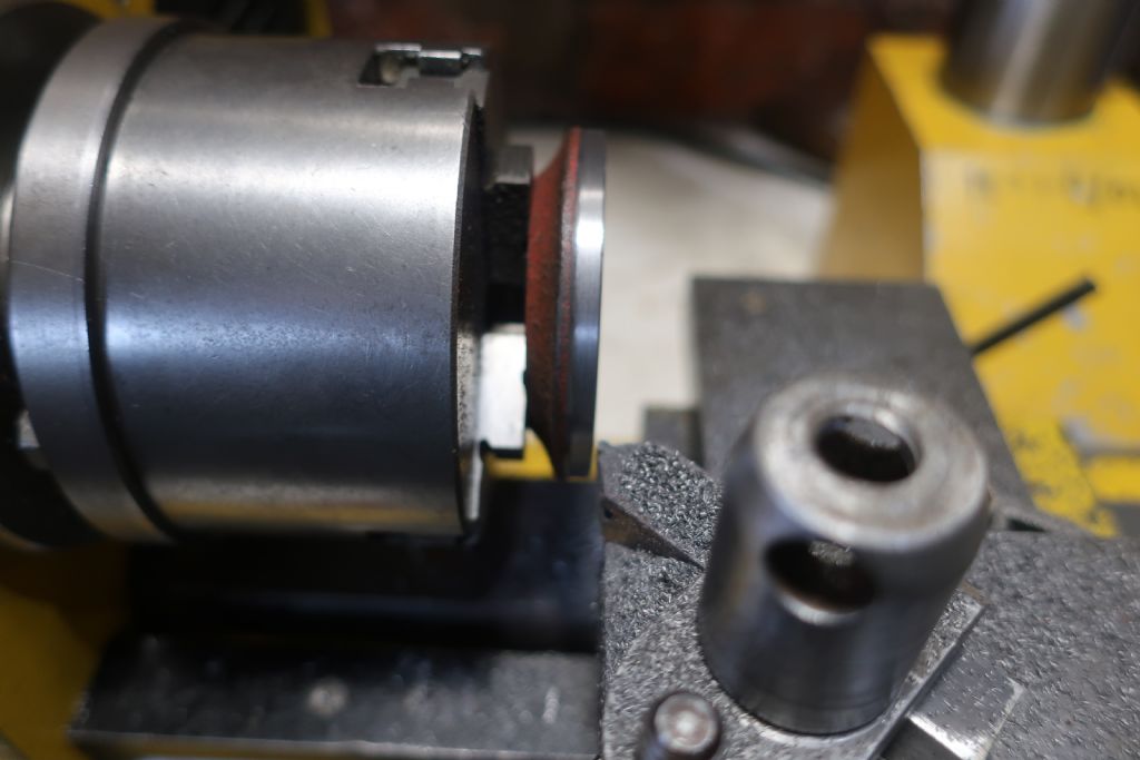
                  The tool cuts as one would wish a neutral-rake carbide tool to cut – the photo's below show a tough cap-head screw of unknown (but tough) grade, and a m/c wheel spindle. The results were from the very first off-hand grinding and are certainly acceptable – the spindle had a huge overhang in spite of being shoved up the 'ole as far as I could get it (and was unsupported at the free end because of the shortcomings of the Hobbymat tailstock).

                  I might make a simple jig to hold the tool for flatting with a lap, just because it's small and slips in the fingers.

                  I still have a couple of ideas to try regarding the the fixing of the toolbit – although the clamp isn't that onerous to make, it still requires a number of set-ups and operations that it would be nice to reduce, and requires compromises to be made the balance of which are difficult to resolve without making and testing.. a number of options are possible, some tried by others, and some perhaps not..

                  I'll update once I get a chance to do more with it..

                  ..also belated thanks to John Haine for his link, and Howard, what was that thread project, and was it successful?

                  img_1188.jpg

                  img_1195.jpg

                  img_1203.jpg

                  #480884
                  Howard Lewis
                  Participant
                    @howardlewis46836

                    No, not a cider press!

                    It is on what will be the column for a shop made Comparator.

                    It is my poor imitation of the Industrial Sigma Comparator, which used a coarse pitch square thread. This one is 8mm pitch.

                    It was an interesting exercise, since, normally I try to avoid screwcutting!

                    The adjuster is just a ring drilled and tapped, so that a 1/8" ball bearing sits half in the Column and half in the Adjuster. The only forces involved are those needed to carry the Arm and the Indicator.

                    "C'est brusque, mais ca marche" as Peugot said.

                    The really interesting bit is going to be the "heat and freeze" to make the column an interference fit in the cast iron base..

                    Howard

                    #480933
                    DiogenesII
                    Participant
                      @diogenesii
                      Posted by Howard Lewis on 19/06/2020 14:09:10:

                      ..It is on what will be the column for a shop made Comparator…

                      Howard

                      Ah! – I really couldn't figure out what you were making, it would have made a great "what is it?"

                      ..that will be a very satisfying one to bring to completion – at risk of being nosey, are you building in order to fulfil a particular need, or is this a project purely for personal interest?

                      #481033
                      Niels Abildgaard
                      Participant
                        @nielsabildgaard33719

                        Hello Diogenes and congratulations on having made a well-working TanTool.

                        Is there some thoughts on vertical level of clamping screw?

                        I put them as close to base as possible to even clamping force over more of bit-bore.


                        Edited By Niels Abildgaard on 20/06/2020 10:05:13

                        #481056
                        Howard Lewis
                        Participant
                          @howardlewis46836

                          Just spotted a MAJOR typo.

                          Depth of thread is 0.0625"!

                          The idea is that the Adjuster will have a 1/8" ball bearing, part in the thread and part in the Adjuster ring, to move the Comparator head up and down the column. There will be a separate clamp to prevent movement once set up.

                          Work is still proceeding, the block to carry the Indicator is not yet finish machined. And then the base needs to be bored to be a slight interference fit on the Column.

                          Then to become a sheet metal worker and make a box to contain and protect it.

                          WHY?

                          No immediate need,

                          It seemed a good idea at the time, since it was a pity for a large diameter 0.0005" Indicator to sit in a box on the shelf.

                          May well submit an article on its construction to Neil for possible inclusion in MEW.

                          Howard

                          #481124
                          Paul Fallert
                          Participant
                            @paulfallert28101

                            Diogenes II

                            Really nice improvements to the tool.

                            For simple lapping, could you skip doing the jig by using your new holder? The angles are already done. The top of the tool bit aligns with the top of the holder (nice touch) and it has a neutral rake. A suitable lapping surface and a little lapping compound (only under the tool bit face).

                            If you wanted to remove a measured amount by lapping, just use a shim under the upside-down holder body, loosen and extend the tool bit. Tighten. Remove shim. Lap until the lap stops cutting.

                            Note: Kitchen foil is around 1 thou thick as is fag paper. I have found various sheets about the house that are half that thickness.

                            ps: Saw an advertisement for "machinist wanted". Work with 200 foot planers and lathes. It said, "your CNC skills are useless here". Ouch!I

                            #481186
                            DiogenesII
                            Participant
                              @diogenesii

                              Thanks all for your comments –

                              Niels, that's a useful observation that I hadn't really considered – I guess I just drilled it halfway up the stock (and then reduced the height, anyway.. maybe I'll add that to the "to do" list.

                              Howard, I understand your motivation completely – I must admit that I have held on to some bits & pieces for years because I have had a destiny (loosely) planned for them, and it's the most satisfying thing to have exercised brain as well as arm in making something worthwhile. It'll be good to see it..

                              Paul, thanks for that – you've thought it through better than I did – I kind of pushed the idea to the back of my mind on the basis that I didn't want to abrade the top "reference" surface, and didn't think much further, but your idea makes sense and is feasible.

                              I'd bought a couple of Dremel diamond cut-off wheels which arrived today and which I used at slow speed to cut the rod into more convenient lengths; using the side also put a perfect flat top onto the bit, so I will see how that goes.

                              I had great success turning and facing without having to adjust the tool position (which was one of the things I was after) this afternoon, on an iron casting..

                              I'll post a description and some pics tomorrow..

                              #481337
                              DiogenesII
                              Participant
                                @diogenesii

                                Following the more-or-less successful trial of the principal, I thought I'd try and find something to cut in a more "real-world" way.
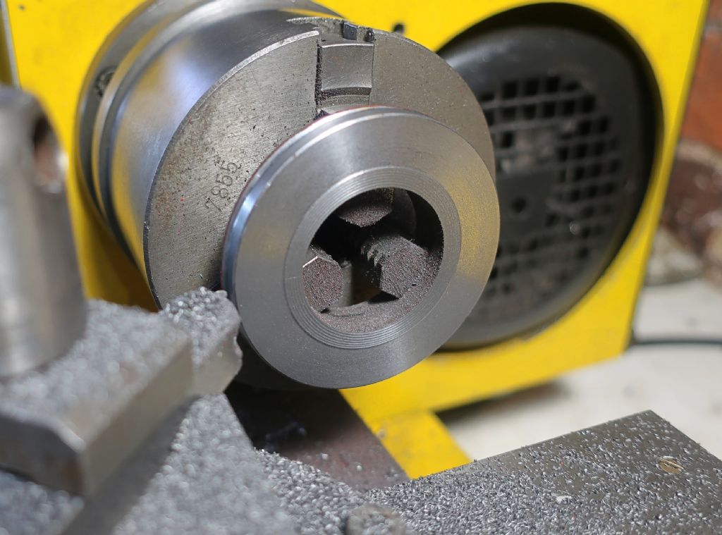
                                I have some "as-cast", 56mm diameter iron collars in the scrap box, and thought that cleaning-up one of these might make a useful subject.

                                img_1215.jpg

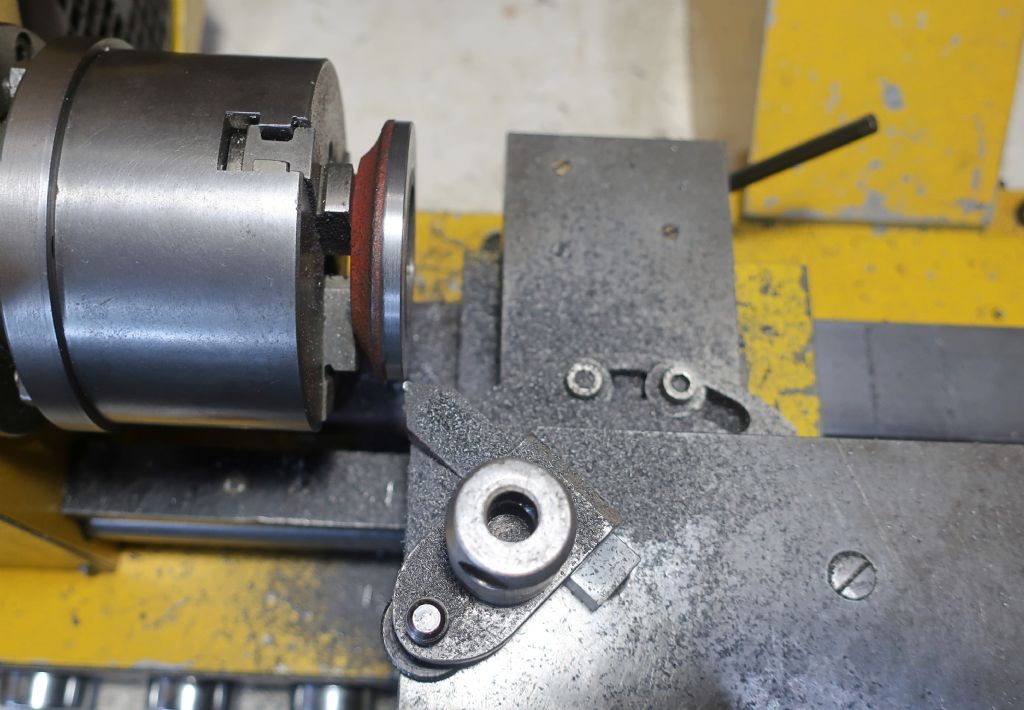
                                The tool was clamped on the topslide at 45 degrees to the lathe axis to enable facing and turning without having to disturb it – it is very compact, and gives good access to the work for measuring etc. At some point I'll replace the clamp stud with a shouldered one, and can then secure the drilled holder directly to the topslide with just a nut & washer.

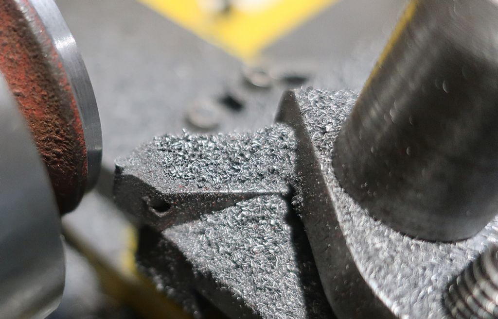
                                The carbide rod was shortened and then ground off-hand with a Dremel "Tile Cutting" diamond wheel (SC545) run at slow speed with the toolbit fitted in the holder to provide a visual guide.

                                img_1216.jpg

                                Cutting performance was good – both in quantity and quality. The tool would cut to radius depth, but felt happier at a bit less than this – perhaps .8mm – which I think is okay for a small lathe spinning CI at 250rpm. The inner "roughing" cut on the face was "pushed" a bit, but still looks crisp & consistent, and the chips from the "skinning" look good. The finishing is certainly acceptable to me in the "normal" working conditions in which it was done – I'm fairly confident that with more careful hand- or fine-feeding and everything snugged up, it would improve further.

                                img_1213.jpg

                                The "Tivoly" brand bit remained in pristine condition at the completion of the job, and also retained it's setting without being pushed down in the holder, so the split clamp may stay just as it is for the present.

                                img_1217.jpg

                                I'm happy with the results. I have a good tool that will reduce the need to change & set (my shamefully haphazard collection of brazed carbide & HSS) tools so often, that doesn't need shimming, and in which the hard toolbit is rigidly held just off the front corner of the soon-to-be-bare topslide.

                                ..I have no doubt a little tweaking and refinement here & there will follow, and I'll try some tougher and some softer, material soon and see what it does with that.. more anon..

                                Thanks for all your help, Niels.

                                #481358
                                Niels Abildgaard
                                Participant
                                  @nielsabildgaard33719
                                  Posted by DiogenesII on 21/06/2020 21:21:22:

                                  I'm happy with the results. I have a good tool that will reduce the need to change & set (my shamefully haphazard collection of brazed carbide & HSS) tools so often, that doesn't need shimming, and in which the hard toolbit is rigidly held just off the front corner of the soon-to-be-bare topslide.

                                  ..I have no doubt a little tweaking and refinement here & there will follow, and I'll try some tougher and some softer, material soon and see what it does with that.. more anon..

                                  Thanks for all your help, Niels.

                                  You are wellcome.

                                  You can always up speed and reduce deepth of cut.Try if You can beg or steel a case-hardened piston pin from a moped or lawnmover repairman.You will be astonished for surface look in the hardened zone but beware of swarf.

                                  #481689
                                  DiogenesII
                                  Participant
                                    @diogenesii
                                    Posted by Niels Abildgaard on 22/06/2020 04:38:12:

                                    Posted by DiogenesII on 21/06/2020 21:21:22:

                                    I'm happy with the results. I have a good tool that will reduce the need to change & set (my shamefully haphazard collection of brazed carbide & HSS) tools so often, that doesn't need shimming, and in which the hard toolbit is rigidly held just off the front corner of the soon-to-be-bare topslide.

                                    ..I have no doubt a little tweaking and refinement here & there will follow, and I'll try some tougher and some softer, material soon and see what it does with that.. more anon..

                                    Thanks for all your help, Niels.

                                    You are wellcome.

                                    You can always up speed and reduce deepth of cut.Try if You can beg or steel a case-hardened piston pin from a moped or lawnmover repairman.You will be astonished for surface look in the hardened zone but beware of swarf.

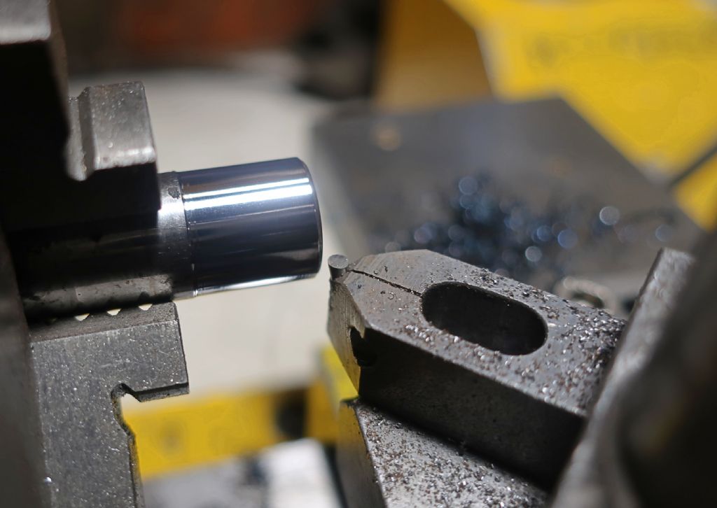
                                    Apologies – I don't know what I was doing when talking about the depth of cut – it was well past my bedtime – somewhere from 0.08 to 0.15 mm reduces the strain on everything, maybe a bit less for finishing..

                                    ..light cuts for this gudgeon/piston pin, but the swarf came off deep blue and left a great finish..

                                    img_1220.jpg

                                  Viewing 16 posts - 51 through 66 (of 66 total)
                                  • Please log in to reply to this topic. Registering is free and easy using the links on the menu at the top of this page.

                                  Advert

                                  Latest Replies

                                  Viewing 25 topics - 1 through 25 (of 25 total)
                                  Viewing 25 topics - 1 through 25 (of 25 total)

                                  View full reply list.

                                  Advert

                                  Newsletter Sign-up