Stuart Twin Victoria (Princess Royal) Mill Engine

Advert

Stuart Twin Victoria (Princess Royal) Mill Engine

Home Forums Work In Progress and completed items Stuart Twin Victoria (Princess Royal) Mill Engine

Viewing 25 posts - 676 through 700 (of 1,260 total)
  • Author
    Posts
  • #606807
    Ramon Wilson
    Participant
      @ramonwilson3

      Just so we are not at crossed purposes I set this up an hour or so ago but was distracted on the F4!

      This shows the test bar I made years ago. Ignore the finish between the measurement areas – that can be as rough as you want. Ignore the rust too – very rare to find anything rusty in the shed but it's been hiding for quite a while.

      Take a shaving cut at this end to true the test area

      dscn0069[1].jpg

      Without moving the tool move the saddle to cut the other end at the same setting

      dscn0070[1].jpg

      By relieving the area between the test areas this speeds the whole process up

      dscn0071[1].jpg

      Advert
      #606809
      Dr_GMJN
      Participant
        @dr_gmjn
        Posted by Ramon Wilson on 21/07/2022 17:41:08:

        Posted by JasonB on 21/07/2022 16:16:07:

        "make your test bar to encompass the crankshaft length and try not to move the tailstock position till the job is done"

        ???

        I think Jason's indicating that you'd already answered a question I'd subsequently asked.

        Thanks both – time to make some physical progress again I think!

        Preparing for a couple of nights cut off on a Pembrokeshire nature reserve island next week, but hopefully will get at least something done on this over the weekend.

        #606810
        JasonB
        Moderator
          @jasonb

          yes that was why I quoted what Ramon had said

          For the same reason once you have got your test bar cutting true you don't want to be having to fit a drill chuck, move the tailstock etc to drill the ends of the embrio crankshaft, So have it drilled ready then you only need to back the tailstock ctr out a couple of turns and slip the crankshaft into place.

          Edited By JasonB on 21/07/2022 18:27:20

          #606813
          Ramon Wilson
          Participant
            @ramonwilson3
            Posted by JasonB on 21/07/2022 18:26:54:

            yes that was why I quoted what Ramon had said

            For the same reason once you have got your test bar cutting true you don't want to be having to fit a drill chuck, move the tailstock etc to drill the ends of the embrio crankshaft, So have it drilled ready then you only need to back the tailstock ctr out a couple of turns and slip the crankshaft into place.

            Edited By JasonB on 21/07/2022 18:27:20

            Ah I see – senior moment on my part.

            Plus one on Jason's advice to have everything prepped. It's one thing to be able to rely on a decent lathe but a well used Myford may not produce the same reliability

            Good luck with it however you do it – just a reminder that the cranks will need to be a good fit on their respective diameters and preferably against a shoulder. I would Loctite and pin them – more than sufficient for this project.

            #606910
            Dr_GMJN
            Participant
              @dr_gmjn

              Cutters arrived today. I went with Jason’s suggestion for types, and got them from Arc Euro Trade. I’ve had a few of the Premium series from them before, and they were very good. I’ve bitten the bullet and ditched the majority of my existing cutters (apart from the known good ones – which I checked on some scrap aluminium). So hopefully there are now no question marks over cutters, should I have any more milling issues.

              #607143
              Dr_GMJN
              Participant
                @dr_gmjn

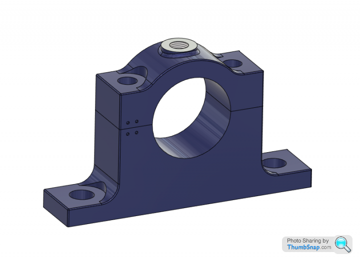
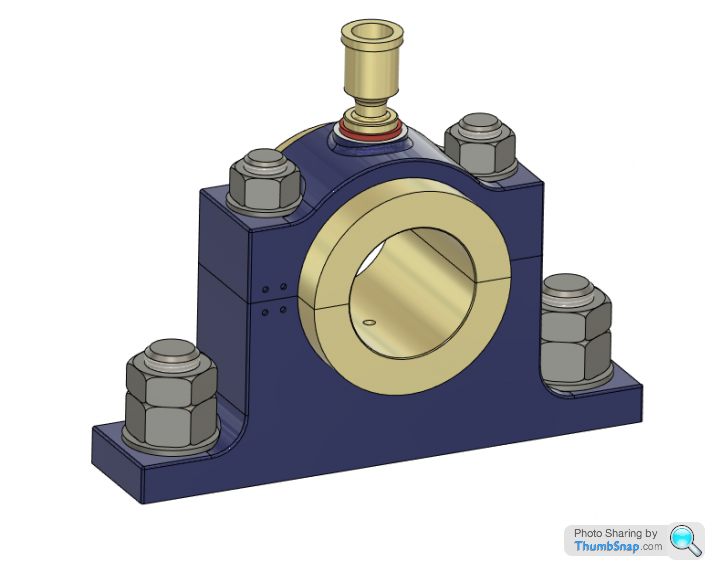
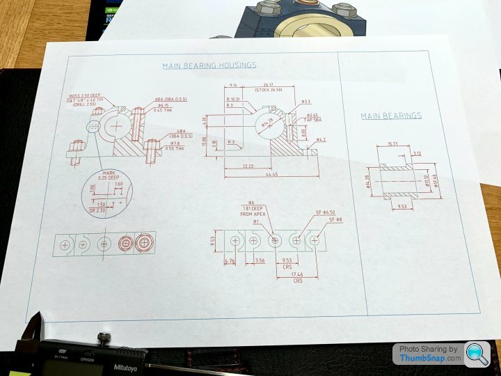
                I've now drawn new ones out on CAD, and done some drawings. I've added some radii features to add a bit of bulk, and tweaked the stud centres to give more room. I think they will look OK:

                Hopefully this will work out. Cheers.

                #607145
                JasonB
                Moderator
                  @jasonb

                  Look good

                  One small point, the locknuts are usually used on the caps with just a single nut holding the pedestal to the bed. The reason for a nut & locknut on the caps is they may not need to be fully tightened down so you need the locknut to stop them coming undone

                  #607146
                  roy entwistle
                  Participant
                    @royentwistle24699

                    I don't recall seeing washers used on mill or winding engines. At least not as here.

                    #607148
                    Dr_GMJN
                    Participant
                      @dr_gmjn
                      Posted by JasonB on 24/07/2022 13:52:45:

                      Look good

                      One small point, the locknuts are usually used on the caps with just a single nut holding the pedestal to the bed. The reason for a nut & locknut on the caps is they may not need to be fully tightened down so you need the locknut to stop them coming undone

                      Thanks for that Jason. I'll swap them round on CAD and see how they look, but to be honest, now the beds are drilled and tapped, there's virtually nowhere to go with this design (as I've seen from your drawing and now my own CAD). I widened the 1" upper body by 0.52 mm outwards each side, but it's enough to give a bit of visual clearance if nothing else. This combined with the 'proper' 4BA lower nuts , should give just enough clearance to a) work, and b) look right.

                      I had no issue milling the cap outer radius on the R/T with only one bolt clamping it around a tight fitting spigot, so I will try that again.

                      The 3 mm blend radii will be an experiment – the upper ones I'll side mill using the R/T, and the lowers with be side milled in the vice. I'm hoping that since the profiles are fairly narrow, my new cutters will be OK.

                      Anyway if it doesn't work out, I'll just remove those radii and revert to how you suggested. I do think it makes a slight visual improvement though.

                      #607149
                      Dr_GMJN
                      Participant
                        @dr_gmjn
                        Posted by roy entwistle on 24/07/2022 14:01:06:

                        I don't recall seeing washers used on mill or winding engines. At least not as here.

                        If I don't use washers, the steel nuts will probably chew up the aluminium faces.

                        Personal preference, but I like to see washers on engineering assemblies, even if they're not strictly prototypical.

                        #607157
                        Ramon Wilson
                        Participant
                          @ramonwilson3

                          So when do we get to which locknut nut goes on first !!!

                          I have quite a few books on industrial stationary engines and it's quite an eye opener when you look at the various images to see where the 'right' way is used – quite rarely in fact.

                          Same with washers – I prefer not to use them but it's a good point on spoiling the paint however a tip to help prevent that is to chamfer the lower corners of the nuts before fitting. Usually quite successful providing it's not 'graunched' up home

                          Nice work Doc – get to it

                          #607159
                          JasonB
                          Moderator
                            @jasonb

                            I've not found a problem with ali parts getting chewed up though I do mostly use cap heads during construction and only fit the studs and nuts at final assembly. Mostly because it's quicker to use a ball ended driver than faff about with spanners or sockets/nut drivers. Paint seems to stay intact when the nuts are finally used.

                            Another option is to go for "washer faced nuts"

                            #607166
                            Dr_GMJN
                            Participant
                              @dr_gmjn
                              Posted by Ramon Wilson on 24/07/2022 14:46:51:

                              So when do we get to which locknut nut goes on first !!!

                              I have quite a few books on industrial stationary engines and it's quite an eye opener when you look at the various images to see where the 'right' way is used – quite rarely in fact.

                              Same with washers – I prefer not to use them but it's a good point on spoiling the paint however a tip to help prevent that is to chamfer the lower corners of the nuts before fitting. Usually quite successful providing it's not 'graunched' up home

                              Nice work Doc – get to it

                              Thanks Ramon.

                              I was looking at a .pdf on steam engine design this week (I think Jason linked to it on my Twin Victoria info thread last year). Looking at engines at our local museum, and a traction engine rally last month, there are examples of washers, locknuts etc being used or not used. Has to be said that washers don’t seem that common at all though.

                              I’ll also work on a drawing for the crankshaft. It looked at it in detail yet, but perhaps steps for the flywheel, governor pulley (on one side), eccentrics, bearings and finally the cast webs?

                              Id like to use a thin flat belt for the governor drive. Ideas anyone have a supplier? I was going to go for a gear drive, but a flat belt will look ok too I think.

                              Question on split bearings: once removed after finishing, does the film of solder potentially make the bearings undersized in one axis?

                              Will be no progress next week – off to deepest darkest Pembrokeshire tomorrow for a couple of nights on Skomer island nature reserve. I wanted to get the drawings ready for when I get back though.

                              Thanks.

                              #607183
                              Ramon Wilson
                              Participant
                                @ramonwilson3

                                If the bearings are tinned beforehand the amount of solder is minimal and is easily cleaned off by a gentle swipe over some fine wet and dry paper on a flat surface using paraffin as a lube.

                                The ideal belts for governor drive are those for turntable drives. They come in various widths and lengths in a flat thin section black rubber with a reasonable stretch but not always available in the length appropriate for the need. I have never tried to cut and join one. The good thing is they don't appear to degrade readily – my oldest, on the Waller engine, still in good shape after many years. An ebay search will find you some I'm sure. I have them in 3mm, 4mm and 5mm wide on the engines with governors.

                                This is the one that I used on the Corliss engine

                                dscn0996.jpg

                                On the Twin Victoria – long before I discovered these belts I used O ring material and always wished I hadn't. The joint constantly broke and it never ever did look right. Even the flat belt is a compromise but it does at least look the part

                                Ideally as said before the shaft would be best made with differing diameters to suit each item it carries. That way none effect the surface for the next as they are slid into position on it.

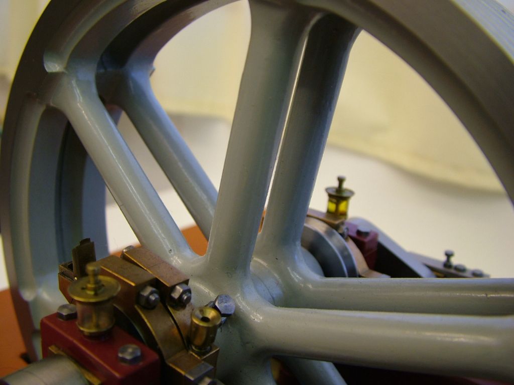
                                The single grub screw retention of the flywheel is a real no no from a scale perspective but by using four, much smaller ones, at 90 degrees to each other they can easily be disguised.

                                Have a great break

                                Best – R

                                Edited By Ramon Wilson on 24/07/2022 16:41:22

                                #607198
                                Dr_GMJN
                                Participant
                                  @dr_gmjn

                                  Thanks Ramon.

                                  I want to try making keys and keyways as per the plans. I’ll have to have a look and see how stepping the shaft might affect that method.

                                  #607209
                                  Ramon Wilson
                                  Participant
                                    @ramonwilson3

                                    I can't recall how it's shown on the drawing Doc and couldn't remember whether I used a key(s) or not.

                                    Found the answer here in this image!

                                    dscf0437.jpg

                                    A compromise at best, if I recall correctly there were three at 120degrees and as with the governor belt something that always irritated and I wished I'd done something better.

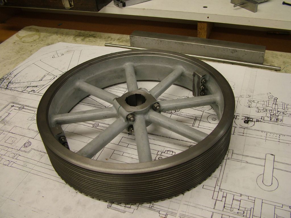
                                    On the Corliss I tried to replicate full size practice and use eight slipper keys – four shallow slots at 90 degrees in the flywheel

                                    corliss project (37).jpg

                                    The shaft has four flats milled on and the flywheel held in place by four keys each side

                                    corliss project (203).jpg

                                    I confess there is a well disguised grub screw in there holding the wheel from any lateral movement !

                                    That may be of interest to you. The big thing with multiple conventional key ways is ensuring they are all in line with each other – slipper keys give you a small but helpful sideways leeway.

                                    #607216
                                    JasonB
                                    Moderator
                                      @jasonb

                                      Not too hard to do the keys to stop the parts from rotating but more difficult to locate the parts along the shaft which really needs tapered keys and the room to insert/extract them unless you combine plain keys with grub screws.

                                      most of the bits that fit this shaft touch side by side so are almost self locating.

                                      #607235
                                      Neil Wyatt
                                      Moderator
                                        @neilwyatt

                                        I remember seeing a full size stationary engine on the cover of Model Engineer that had washers under its nuts.

                                        Neil

                                        #607238
                                        Ramon Wilson
                                        Participant
                                          @ramonwilson3

                                          Washers under its nuts? Now that's a painful condition Neil!

                                          Jason when I said multiple keyways I was referring to radially as some full size flywheels had.

                                          I don't key the cranks as most, though not all of course, had the crank webs shrunk on. Unless for scale representation there is no need – a close Loctite fit and pinned preferably from the end of the crank web and not through the side – is more than adequate.

                                          Though eccentrics should be keyed the position has to be pretty accurate radially – one instance where a socket grub screw is definitely beneficial when setting the valves so yes I do 'cheat' there. If a small hole through the eccentric strap on the centreline can be accepted then the strap does not have to be removed for altering the position when setting takes place.

                                          #607243
                                          Neil Wyatt
                                          Moderator
                                            @neilwyatt

                                            for john.jpg

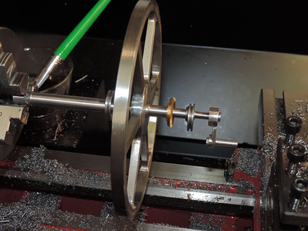
                                            Fit testing another multi-diameter crankshaft. This will use keys.

                                            #607260
                                            Dr_GMJN
                                            Participant
                                              @dr_gmjn

                                              Thanks guys.

                                              The P.R. Uses two tapered keys at 120 degrees spacing for the flywheel. They are secured with small grub screws. It says one may need to be stepped if the keyways aren’t perfectly spaced. I’m thinking I could get the spot-on for the shaft, using the R/T, but not sure how I make yeyways in the flywheel to begin with, never mind spacing them perfectly! I’ll have to re-read the article.

                                              I drew out the crankshaft assembly last night – there are gaps between the components, so some axial adjustment is possible – and probably necessary for the eccentrics, so my steps will have to be a bit longer than each corresponding part boss I guess.

                                              The eccentrics have two grub screws spaced at 90 degrees.

                                              The pulley has a single grub screw.

                                              One crank web is specified as a press fit, the other a less tight fit, ultimately secured with loctite (this is so that things can be disassembled from one end when test building/painting etc.)

                                              Cheers.

                                              #607267
                                              Ramon Wilson
                                              Participant
                                                @ramonwilson3

                                                Doc, a small tip.

                                                Where the eccentrics (and pulley) sit turn a shallow slot just wide enough for the grub screws to sit. Use a dog point on one and a cone point on the other screw. Use the dog point one for initial setting and once established tighten the cone point to fix it's position securely. By turning a shallow groove you won't deface the surface of the shaft with the grub screws.

                                                You can slot the flywheel in the lathe easily enough but getting the two exactly 120 degrees apart won't be unless you can move and lock the head the desired amount – not easy on an ML7with it's 65 tooth bull wheel unless you have a dividing method that locates in the rear of the spindle.

                                                Personally I'd just do the one if the dividing becomes an issue.

                                                Have a safe journey – looks like you might get some rain

                                                #607275
                                                Hopper
                                                Participant
                                                  @hopper
                                                  Posted by Dr_GMJN on 24/07/2022 13:46:20:

                                                  I've now drawn new ones out on CAD, and done some drawings. I've added some radii features to add a bit of bulk, and tweaked the stud centres to give more room. I think they will look OK:

                                                  Hopefully this will work out. Cheers.

                                                  And good to see you have your locknuts right way round — for the 19th century, true to prototype. Thick nut on top is a new 21st century development (backed by science) but was unheard of in the days of steam engines as their heavy flogging spanners would not fit the thin nut on the bottom whilst belting it with a 28lb hammer. Even in the 1970s, marine engineering examinations demanded thin nut on top in the technical drawing exam.

                                                  Following your thread with interest. Nice work. Looking very good.

                                                  Edited By Hopper on 25/07/2022 10:07:07

                                                  #607341
                                                  Ramon Wilson
                                                  Participant
                                                    @ramonwilson3

                                                    The nut on top or below is a bit of an old chestnut Hopper that's more than done enough of it's share of the rounds eh?

                                                    I have an open mind on the subject but it's interesting to hear it's a 20th century thinking and not before, something I was not aware of. That would help explain the lack of it's appearance (thin on bottom) in so many of the images I have.

                                                    Hmmm! that now makes my Corliss engine pre 1900 wink

                                                    Tug

                                                    #607343
                                                    JasonB
                                                    Moderator
                                                      @jasonb

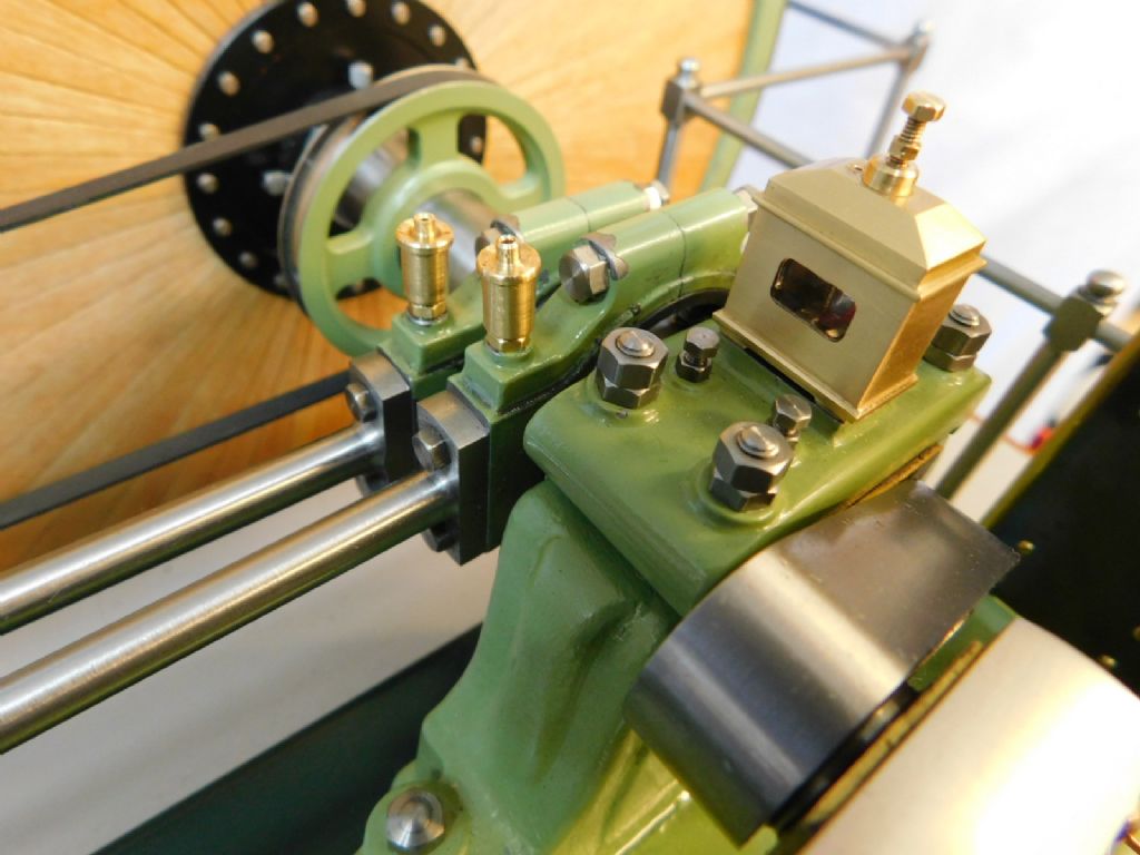
                                                      Knowing how he likes things exact I'm just wondering how many nuts the Doc will get through to make the two flats line up like the imagessmile p

                                                      For those that like looking at old nuts this is the "handbook on steam engines" that Doc mentions, interestingly the third edition published in 1902 shows locknuts below full nuts and some washers too

                                                      Edited By JasonB on 25/07/2022 18:38:40

                                                    Viewing 25 posts - 676 through 700 (of 1,260 total)
                                                    • Please log in to reply to this topic. Registering is free and easy using the links on the menu at the top of this page.

                                                    Advert

                                                    Latest Replies

                                                    Viewing 25 topics - 1 through 25 (of 25 total)
                                                    Viewing 25 topics - 1 through 25 (of 25 total)

                                                    View full reply list.

                                                    Advert

                                                    Newsletter Sign-up