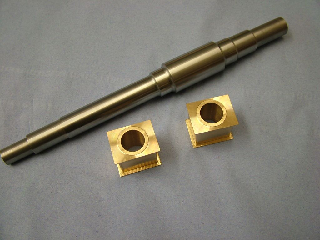
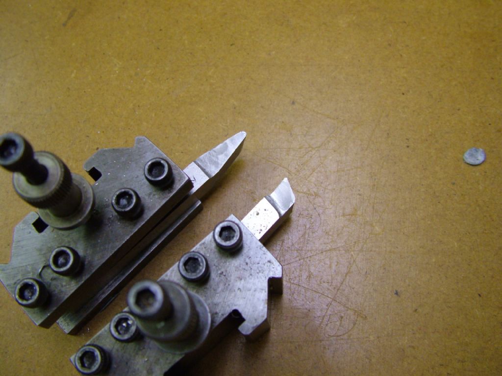
Stuart Twin Victoria (Princess Royal) Mill Engine

Advert

Stuart Twin Victoria (Princess Royal) Mill Engine

Home Forums Work In Progress and completed items Stuart Twin Victoria (Princess Royal) Mill Engine

Viewing 25 posts - 651 through 675 (of 1,262 total)
  • Author
    Posts
  • #606502
    JasonB
    Moderator
      @jasonb

      There is a reason many model engineers use 1 size smaller BA hex fixings. I also use 1 size smaller metric hex so the 3BA nuts would only be about 6.3mm A/F not 7.2mm.

      I'll list some cutters in the morning.

      Edited By JasonB on 19/07/2022 20:48:06

      Advert
      #606531
      Dr_GMJN
      Participant
        @dr_gmjn

        So checking some sizes, the 5BA bolts I’ve used on the caps have 6BA heads:

        So – somehow, and unintentionally – I have ended up with a size smaller than the plans, but they still don’t ‘work’ visually.

        The cap stud spacings and base stud spacings are as per the plans, yet they call for slotted base holes, which are pointless because there is no room for any adjustment at all with 3BA nuts.

        Unless there’s some odd standard where 5BA nuts are bigger than the bolt heads, then the 5BA nuts would overhang the caps. If they didn’t overhang, the 2BA base nuts wouldn’t turn, since they’d hit the pedestal sides.

        OK it’s been a long hot day, but I’m confused. I might just start again with the cap design and move the stud centres inwards, using 6BA nuts and studs. Might even make the bronze bush OD a bit smaller too; 1mm either way would make all the difference.

        #606551
        DiogenesII
        Participant
          @diogenesii

          Looks like your bolts are 'one-size-smaller', but your nuts are std. BA – o/s/smaller nuts are available, I know the likes of EKP do them.

          Mr B (and Mr W) have an eye for detail and proportion that it can be hard to emulate – I've been trying to make some caps fpr an IC engine, and trying to get something that looks like I want ti too is SO hard – the drawn ones are unconvincingly 'lumpish', trying refinements to make them them look 'scale' 'elegant' and 'right' is becoming on of the hardest parts of the job..

          Edited By DiogenesII on 20/07/2022 06:42:26

          Edited By DiogenesII on 20/07/2022 06:52:35

          #606554
          JasonB
          Moderator
            @jasonb

            DiogenesII, why not put an image of your caps in a new thread so we can see what can be done.

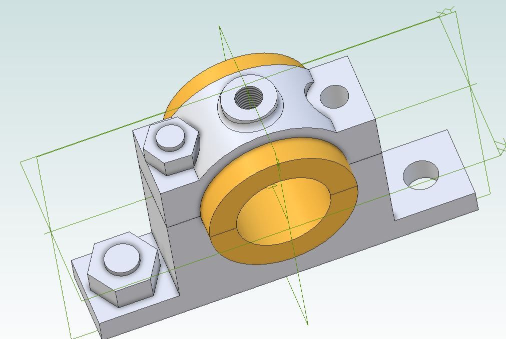
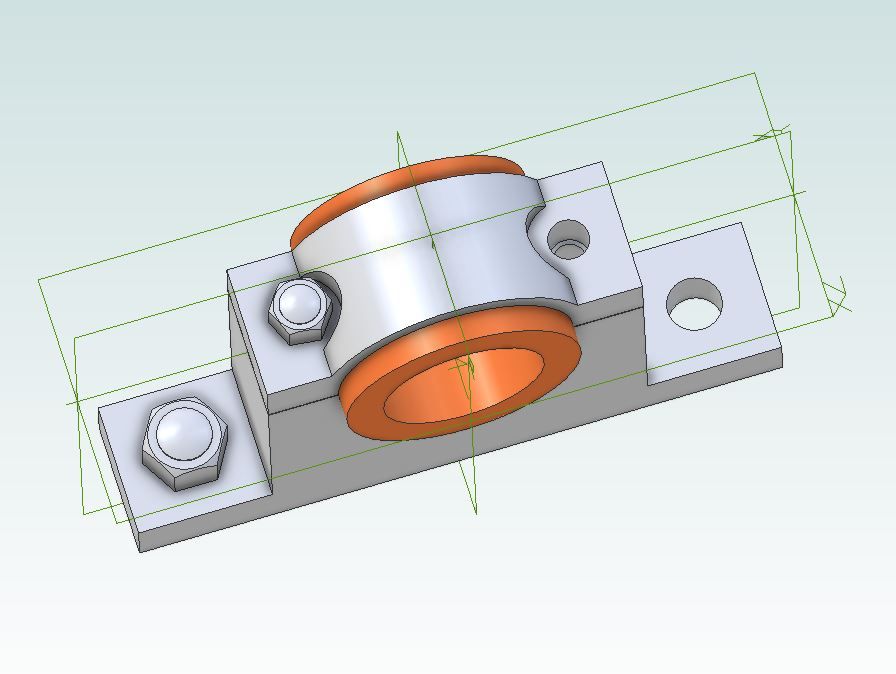
            Doc have you checked your 3BA nuts are the correct size as they fit on the CAD model, though as I said a 1mm fillet would foul. Not unknown for BA nuts to now be made from the nearest available metric hex as it becomes harder to source the old sizes and 3BA is a non preferred size so more likely yo disappear first.

            The 5BA ones are too tight so you could revisit the counterbore with a larger cutter or use 1 size smaller nuts, I'd go for smaller nuts to save remaking things This is with standard 3BA and 5BA

            3ba.jpg

            This is the one from the recent Real which uses M4 and M3 both one size smaller metric nuts

            m4.jpg

            Tubal Cain was certainly not averse to using 1 size smaller nuts and particularly given this is a 1/16-1/24th scale model more than likely he did though text suggests the 3BA were standard.

            #606560
            Ramon Wilson
            Participant
              @ramonwilson3

              Yes, I can confirm one size smaller BA nuts are available from EKP plus several others and they are used constantly throughout my builds. On the smaller sizes I sometimes tap the next smaller nuts out too ie 10 BA Nuts with 8BA thread.

              So far have not used any metric.

              In my opinion the standard size nut (and head) and the odd BA sizes as specified by Stuarts are way overscale and require a rethink on all uses – for a more scale effect.

              All the 1BA hold down nuts on the Corliss engine were made from scratch to achieve this so that's another alternative

              #606562
              JasonB
              Moderator
                @jasonb

                Cutters

                If we stick with HSS for steel & iron then I've suggested 3-flute cutters many a time as good all rounders, ARC used to be a bit expensive in the smaller sizes but at the moment their prices are good just like the cutters so the Premium 3-flute standard length cutters would be what I suggest from them. Prior to ARC's price reduction then these from APT were a good buy – you need to add VAT to those prices so not such a good buy now.

                For aluminium then the cutters specifically for it work well and also on brass and bronze. I tend to use the carbide ones, all that bearing base and cap were done with a 10mm one of these which has had a lot of use and still going strong. You could also go HSS as the Carbide can be a bit delicate if you are not careful. Another Carbide option would be the 3-flute from APT which I use on the CNC

                #606622
                Dr_GMJN
                Participant
                  @dr_gmjn

                  Thanks Both. Before doing anything drastic, I'm going to finish boring the first one, and look at perhaps just making new washers that match the point-to-point nut dimension, rather than exceeding it slightly. I think if the nuts are orientated such that the flats are in the vicinity of the edge, then it might just look ok.

                  Alternatively, might look at tapping a 7BA nut to 5BA as per Jason's diagrams (if it fits).

                  I noticed that my 6BA studding did screw into the blocks fairly well, and didn't feel too dodgy. This sounds like a terrible bodge, but could I JB weld 6BA studs into the block, and use undersized nuts (ie 7BA). That would give much more clearance at the expense of the bodge itself, and the nuts looking a bit small.

                  I will order the cutters now, because I got the impression yesterday that the one I was using for the sides of the bocks was a bit blunt – the long chips weren't as defined as the ones generated with the other cutter I used for shaping the blocks. Strange because it's hardly used (despite being old). It's a Guhring cutter, so not a bad brand either. I am wondering if these cutters have (as mentioned previously) been the main source of my frustrations with the mill. Perhaps they are prone to rapid dulling of the cutting edges?

                  One other question about the split bearings: My local supplier can't supply bronze or gunmetal in those sizes, but he does have brass. Would brass be OK?

                  Thanks.

                  #606629
                  Dr_GMJN
                  Participant
                    @dr_gmjn
                    Posted by DiogenesII on 20/07/2022 06:36:05:

                    Looks like your bolts are 'one-size-smaller', but your nuts are std. BA – o/s/smaller nuts are available, I know the likes of EKP do them.

                    Mr B (and Mr W) have an eye for detail and proportion that it can be hard to emulate – I've been trying to make some caps fpr an IC engine, and trying to get something that looks like I want ti too is SO hard – the drawn ones are unconvincingly 'lumpish', trying refinements to make them them look 'scale' 'elegant' and 'right' is becoming on of the hardest parts of the job..

                    Thanks for that – I hadn't appreciated the "one size smaller" thing – never heard of it before, or if someone on here mentioned it – apologies, but it just didn't register what it meant.

                    Bottom line is I measured the 3BA mount nuts as a check, and they are 8.16mm A/F, whereas they should be 7.16 A/F. So, had I sized the lower mount flanks on correct nuts, I wouldn't have had to take as much off, and the cap nuts would also have fitted.

                    So I'm going to re-make the first block from scratch, and then machine both to a 3BA one-size-smaller, ie 4BA. This should then give me ample clearance on everything.

                    I really hope I've understood the above correctly…

                    Thanks all.

                    #606706
                    Dr_GMJN
                    Participant
                      @dr_gmjn

                      Thought I’d carry on a bit with the scrap bearing block, just to get practice machining the bore and cap radius while the new cutters and a selection of BA fasteners arrive.

                      With a coat of paint, which highlights the washers and bolt heads:

                      I’m happy with the form of them, hopefully with the smaller base nuts (on order) I’ll be able to get a radius in there too. The cap bolt spacing definitely needs attention, so I’ll draw it out on CAD, and re-make both bearings from scratch. Put it down to experience!

                      Re. The crankshaft – when I’ve turned the diameters, is there any finishing process I should use, maybe spinning with a piece of fine abrasive to get rid of the machining marks? I’m planning on using a GT insert (which was the best one for steel on the 10V), turning between centres.

                      Thanks.

                      #606730
                      Ramon Wilson
                      Participant
                        @ramonwilson3

                        Personally I would use HSS to obtain a fine and accurate diameter. Yes it can be done with carbide but you need to scrape that last few thou to a fine surface and maintain diameter. Much easier to do with a freshly ground piece of HSS

                        A round nosed taper tool will cut the radius at any increase in diameters as well as providing the fine control

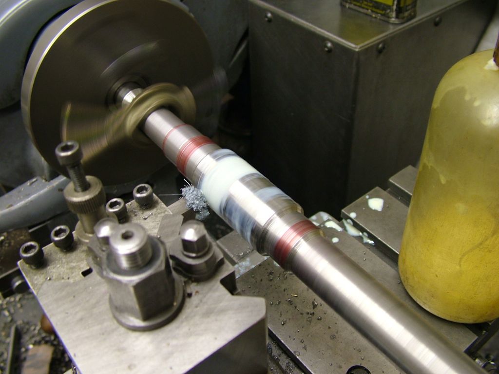
                        Here's mine in use on the Corliss shaft (note the shaft is pre machined and is set between centres for finish turning – turning the shaft around to finish each end at the tailstock end)

                        corliss project (64).jpg

                        corliss project (65).jpg


                        corliss project (66).jpg


                        Using HSS gives a finish that allows a fine polish with wet and dry paper to bring to an almost ground like appearance without losing dimension to any great amount.

                        Jason as a confirmed carbide devotee will have other ideas but that's what I would do.

                        What material do you intend to use – EN1a free cutting steel is the best option when running on bronze or brass – a very good combination. The last material I would turn too would be silver steel. Not a good choice in my opinion for this specific item.


                        Just another thought – it should go without saying but you need to have your bearings finished (but not slit at this stage) to use as gauges and like wise the flywheel bore – much easier to do than the other way round. By machining between centres you can safely remove the shaft to check the fits  – off the lathe

                        Edited By Ramon Wilson on 21/07/2022 08:13:00

                        Edited By Ramon Wilson on 21/07/2022 08:17:36

                        #606734
                        Dr_GMJN
                        Participant
                          @dr_gmjn

                          Thanks Ramon. Is there any chance you could sketch the HSS profile I’m aiming for?

                          Re. The shaft/bearing fit: a few posts back, Jason suggested making the shaft first and boring the bearings to suit!

                          Cheers.

                          #606738
                          Ramon Wilson
                          Participant
                            @ramonwilson3

                            Well each to his own Doc but it should be quick to realise that it is much easier to make the bearings and other bores first – preferably with standard sized holes and then make the shaft to fit – as said, unlike a chuck or even a collett if done between centres it can be removed without fear of movement and the shaft parts are much easier measured than bores – ie you'd need to carefully measure the bores to the correct size to suit the shaft and try the shaft in the part rather than the other way round – apart from the flywheel and unless there's no option it's not the ideal way to go about this task.

                            Just 'polishing' the shaft until the parts slip on is much the easier way.

                            Here's a pic of the tapered tool. It's one that gets probably more use than any other from a finishing aspect – works in either direction and is ideal for turning those unimportant radii by eye such as transition on crankshafts etc

                            dscf0614.jpg

                            You have to bear in mind Doc that my advice comes from a time when this way of work was standard in a jobbing shop – get the job done but accurately and at low cost (ie time) with what you had at your disposal bearing in mind the machinery available – no CNC in those days and carbides used only for roughing. In forty odd years of machining I only saw a solid carbide endmill in my last three years – and they were only used on the new Haas machining centre.

                            I always try to offer my advice well aware of the limitations of an ML7 and the issues you have with your mill

                            #606757
                            JasonB
                            Moderator
                              @jasonb

                              My comment about doing the bearings after assumed you already had 7/16" material and would apply to anyone else making from a kit where 7/16" material is supplied by Stuarts.

                              As this is nominal 7/16" it is likely to be smaller by a thou or two. Most hobbyists will not have bore gauges and the most likely tool they will have to hand is a digital calliper which will be hard to accurately measure the bore of the bearing with. So could easily end up oversize and no amount of abrasive will add metal to a 0.436" shaft if you have made your bearing to a standard 0.4375".

                              That is why I said bore the bearing using the shaft material as a plug gauge


                              Edited By JasonB on 21/07/2022 11:41:37

                              #606769
                              Ramon Wilson
                              Participant
                                @ramonwilson3

                                Unless it's Precision Ground Mild Steel bar Jason no stock material would really be suitable due to the reason you state – likely to be undersize. I don't know what Stuart supply but didn't Doc say he only bought castings?

                                Short of using PGMS two thou down is not an ideal starting place unless as you say the bearing is turned to suit and not reamed to stock size – that would be a rattle fit as far as a main bearing tolerance is concerned let alone the fact that basic stock material is not truly round either – even silver steel

                                It's 'horses for courses' of course but I would have assumed anyone making an engine of this nature would make the bearings and shaft a very good running fit to each other.

                                If I were to make another of this design I would certainly make the shaft with stepped diameters for ease of assembly. ie no spoiling of the running surfaces as the fly wheel and eccentrics are positioned. Once the cranks go on of course, that's it.

                                One thing I learnt early on was it makes life much easier if, for most part, you put the horse in front of the cart wink


                                PS PGMS incidentally is a lovely material to turn further if required – probably close to EN1a free cutting. It turns and screw cuts extremely well. I think EKP offers it as well as M-Metals

                                Edited By Ramon Wilson on 21/07/2022 12:54:27

                                #606770
                                Dr_GMJN
                                Participant
                                  @dr_gmjn

                                  Ramon Jason,

                                  OK so there's been a bit of confusion here:

                                  I based the material requirements for this build on the M.E. Articles, which specify the crankshaft as being turned between centres from 1/2" stock – which is what I bought ages ago. I just checked, and I've also got some 7/16" 080A15 steel (probably bought based on what was in the Stuart materials listing – before deciding to build the P.R.). As per Jason's comment it is 0.0015" undersized.

                                  Not sure why the article specifies over-sized stock in the first place though?

                                  Anyway, I'll use the 7/16" stock and bore the bearings to suit. I assume between centres is the best way, or would setting up in the 4-jaw be OK; I'll only be turning the end 9mm or so down to fit the crank webs?

                                  I've learned a lot from the last few posts about "one size smaller" fasteners, and machining to sizes – it can be confusing, perhaps more so for you guys who might think I'm ignoring various bits of advice, but it's all good I think.

                                  The new milling cutters arrive tomorrow, and I'm getting the brass and steel gauge material this afternoon all being well.

                                  #606775
                                  JasonB
                                  Moderator
                                    @jasonb

                                    If you have both then turn the 1/2" between ctrs taking note of Ramons comment about stepped diameters as having the middle 1/32" larger for teh flywheel would be a good option as if your bearings end up too much larger than teh flywheel bore you won't get the flywheel on over the correctly polished bearing surfaces as they will be larger.

                                    Stuarts just supply bright mild steel with all their kits this is why I always suggest the method I described as using a typical H7 reamer will give sloppy bearings and also likely lead to a wobbly flywheel too. Using the supplied stock as the plug gauge you can get the fits for the bearings a little easier than the fit of the flywheel and eccentrics as you want a running fit for the bearings and somthing a bit firmer for the others which is hard to measure with the average digital callipers that many will have.

                                    I also depends on the job in hand. many of the large hit and miss engines I build come with cast cranks so may not finish to the requiered size needing to be cut smaller to get a fully machined surface so as they would be expensive to replace if even still available I'd rather make the crank to a good finish and then size other parts to suit as if I overcut a bearing it's mot the end of the world to make another.

                                    Likewise built up crankshafts either silver soldered or loctited these are built up with finished size material usually PGMS so don't see the point in machining those down and would rather use the shaft or some spare material as the plug gauge to size other parts.

                                    Another thing to consider is if boring your flywheel to a standard 7/16" is can you ensure there is no taper to the bore and the far end is not smaller? Having the crankshaft material to size and to hand you can simply slip that into the hole and ensure it goes all the way in. If it starts getting tight it is very easy to just take another spring pass. If you find the bore is tapered once you take it off the lathe it will be a lot harder to correct.

                                    If you are going to ream the flywheel which should give a parallel bore there is a risk of the drill deviating due to hard spots or voids and the reamer will just follow equals wobbly flywheel. Some say drill – bore – ream but if you have the boring bar in you may as well bore all the way. and get those small difference sin fit unless you want to splash out on 0.01mm increment reamers.

                                    Edited By JasonB on 21/07/2022 13:16:01

                                    #606779
                                    Ramon Wilson
                                    Participant
                                      @ramonwilson3

                                      Well, as said so long before – "Listen to all, make your own mind up and go for what you consider best"

                                      Jason has built some fine engines and his skill is not in doubt. Often, however, I see things from a different perspective and try to convey that – not in opposition or disagreement but from an ease of machining perspective to arrive at the best accurate result with limited kit.

                                      In an ideal world the shaft would be drawn with dimensions clearly toleranced as would the components to fit it. Each tolerance, if worked within, would ensure the correct type of fit. As we are not in an ideal world so compromises have to be made.

                                      So – stock material – in my book all you can do is measure it and make everything that goes on it to suit – Flywheel, bearings, eccentrics and cranks – we haven't even got to fitting them yet. Stock material rarely has a surface finish you can accept for such a fit as a running bearing. Okay, maybe, for line shafting but you are making a precision item. Each bore has different requirements so all need separately required measurement. If however, all are bored beforehand – even if slightly different in tolerance, then the shaft can be made to fit each part – much easier to do with the shaft off the lathe than trying to insert the shaft in a small item in the lathe (flywheel excepted) To use stock material as a plug gauge in order to turn a fit suitable for a running bearing is not, in my opinion, a way to go about obtaining such a fit.

                                      So, in my simplistic approach, the parts require a uniform bore (of varying diameters if desired) and the shaft is turned to suit – easily measured for certain – and the shaft brought to size to suit each component.

                                      The book text, you say, confirms what I'm advocating – turning the shaft from larger material.

                                      There you go then Doc – paying money and choosing is your optionsmiley


                                      Best – R


                                      Edited By Ramon Wilson on 21/07/2022 14:03:28

                                      #606786
                                      Dr_GMJN
                                      Participant
                                        @dr_gmjn

                                        Thanks both.

                                        So for turning between centres – I was going to set up the tailstock specifically for this job, because IIRC last time I set it up, it was slightly off depending on position (it's an old lathe).

                                        What is your preferred procedure for doing this? Test bar of similar length and measure/adjust until machined areas at both ends measure the same?

                                        Then – spring cuts once finished size is approached to take out any deflection of the workpiece in the middle.

                                        PS – somewhat adding to the confusion is sometimes on here a post doesn't appear until after someone else has replied to it…for example, Ramon's comment about making the flywheel bearing surface bigger didn't appear until after Jason referred to it – caused some head scratching!

                                        I'll sketch a modified crankshaft up, and post it for comment at some point.

                                        #606789
                                        Ramon Wilson
                                        Participant
                                          @ramonwilson3

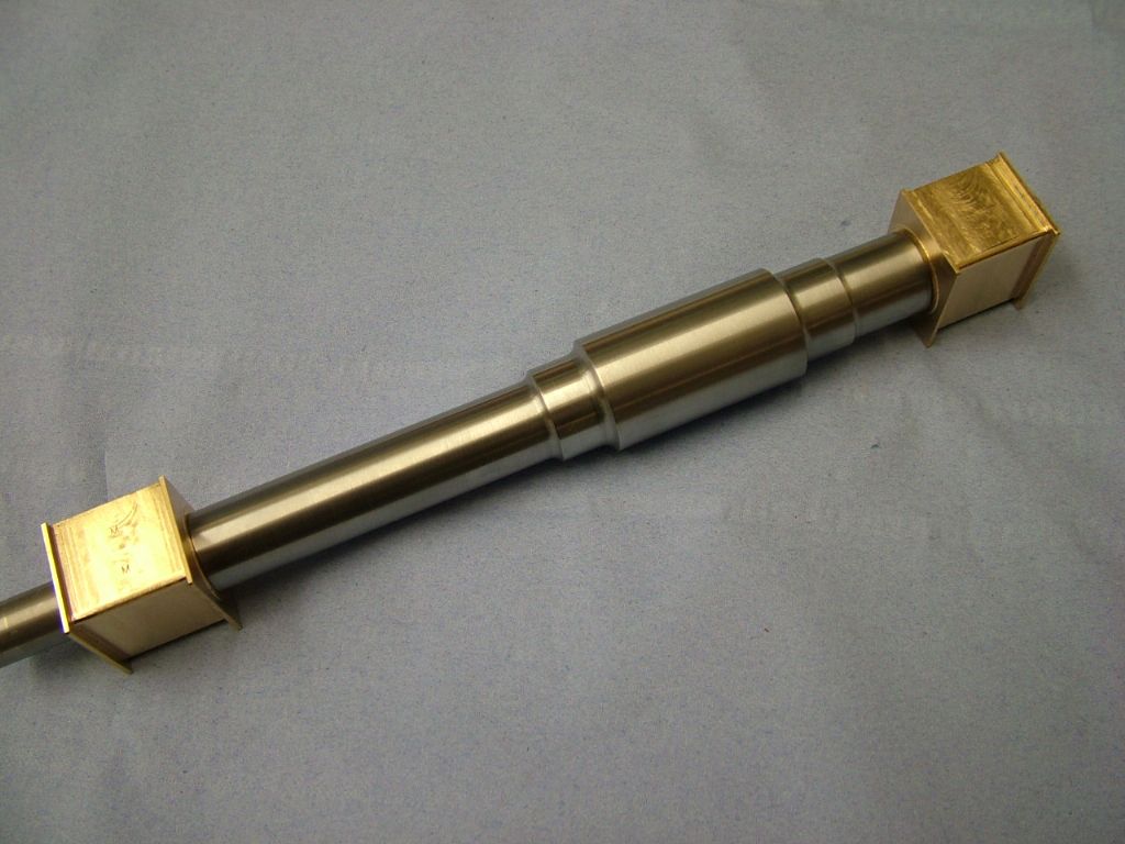
                                          Make yourself a between centres test bar Doc –

                                          Take a piece of mild steel about 1/2 to 5/8 diameter and turn about an inch in at each end to about 3/8 to 1/2 diameter. Centre deeply each end as you do it. Set between centres and turn the middle part to roughly the same depth – finish is totally unimportant leaving portions of the full diameter about 3/4 long at each end.

                                          Now take a very fine cut across the large diameter section nearest the tailstock and not changing the cross slide setting move the carriage to the section near the chuck and repeat. Try to get as a good a finish as possible – you only need to take a few thou off.

                                          Measure each end and adjust the tailstock accordingly to any difference found – put a clock on the tailstock and adjust to half the difference – take another test cut and measure again. Unlikely you'll get it perfect but within a thou is good over 8 inches or so. Bear in mind that depending on the state of the lathe that's only as accurate as the bed is in shape so make your test bar to encompass the crankshaft length and try not to move the tailstock position till the job is done. By doing this you don't have to cut that portion between the measuring spots.

                                          When turning the shaft work in from each end of the shaft from the tailstock end – reversing the shaft to do so. This will minimise any errors and be as accurate as your lathe and your measuring will allow

                                          If you can't quite picture what I mean I'll take a picture of the one I made years ago – still in use on the original larger diameters.

                                          Hope that helps

                                          Edited By Ramon Wilson on 21/07/2022 16:01:54

                                          #606791
                                          Dr_GMJN
                                          Participant
                                            @dr_gmjn
                                            Posted by Ramon Wilson on 21/07/2022 15:59:39:

                                            Make yourself a between centres test bar Doc –

                                            Take a piece of mild steel about 1/2 to 5/8 diameter and turn about an inch in at each end to about 3/8 to 1/2 diameter. Centre deeply each end as you do it. Set between centres and turn the middle part to roughly the same depth – finish is totally unimportant leaving portions of the full diameter about 3/4 long at each end.

                                            Now take a very fine cut across the large diameter section nearest the tailstock and not changing the cross slide setting move the carriage to the section near the chuck and repeat. Try to get as a good a finish as possible – you only need to take a few thou off.

                                            Measure each end and adjust the tailstock accordingly to any difference found – put a clock on the tailstock and adjust to half the difference – take another test cut and measure again. Unlikely you'll get it perfect but within a thou is good over 8 inches or so. Bear in mind that depending on the state of the lathe that's only as accurate as the bed is in shape so make your test bar to encompass the crankshaft length and try not to move the tailstock position till the job is done. By doing this you don't have to cut that portion between the measuring spots.

                                            When turning the shaft work in from each end of the shaft from the tailstock end – reversing the shaft to do so. This will minimise any errors and be as accurate as your lathe and your measuring will allow

                                            If you can't quite picture what I mean I'll take a picture of the one I made years ago – still in use on the original larger diameters.

                                            Hope that helps

                                            Edited By Ramon Wilson on 21/07/2022 16:01:54

                                            Thanks Ramon – I've got a test bar, but the question was should I size it in length to approximate the workpiece?

                                            #606792
                                            JasonB
                                            Moderator
                                              @jasonb

                                              "make your test bar to encompass the crankshaft length and try not to move the tailstock position till the job is done"

                                              #606793
                                              Ramon Wilson
                                              Participant
                                                @ramonwilson3

                                                How long is it in comparison to the shaft ? – if its well over long then any error will increase if you need to bring the tailstock closer to the chuck to machine the shaft

                                                Ideally you want the tailstock quill extended an inch or so when you take a test cut with the tailstock in the approximate position you are going to use to turn the shaft. That way you don't move the tailstock only the quill to get the shaft in and out after you have set your tailstock.

                                                I should have said – lock the quill before taking the test and adjusting making sure you do the same when turning the shaft.

                                                #606794
                                                JasonB
                                                Moderator
                                                  @jasonb

                                                  Don't forget to face and ctr drill the shaft before you start taking test cuts as you don't want to be disturbing ctrs or the tailstock

                                                  #606805
                                                  Ramon Wilson
                                                  Participant
                                                    @ramonwilson3
                                                    Posted by JasonB on 21/07/2022 16:16:07:

                                                    "make your test bar to encompass the crankshaft length and try not to move the tailstock position till the job is done"

                                                    ???

                                                    #606806
                                                    Ramon Wilson
                                                    Participant
                                                      @ramonwilson3
                                                      Posted by JasonB on 21/07/2022 16:25:20:

                                                      Don't forget to face and ctr drill the shaft before you start taking test cuts as you don't want to be disturbing ctrs or the tailstock

                                                      Not sure what you mean here either Jason – the bar would be faced and centred initially – that plays no further part. The only thing to be cut is the two end pieces on their diameters

                                                    Viewing 25 posts - 651 through 675 (of 1,262 total)
                                                    • Please log in to reply to this topic. Registering is free and easy using the links on the menu at the top of this page.

                                                    Advert

                                                    Latest Replies

                                                    Viewing 25 topics - 1 through 25 (of 25 total)
                                                    Viewing 25 topics - 1 through 25 (of 25 total)

                                                    View full reply list.

                                                    Advert

                                                    Newsletter Sign-up