Starter Switch

Advert

Starter Switch

Home Forums General Questions Starter Switch

Viewing 25 posts - 1 through 25 (of 39 total)
  • Author
    Posts
  • #25550
    Andy Sproule
    Participant
      @andysproule22368
      Advert
      #320889
      Andy Sproule
      Participant
        @andysproule22368

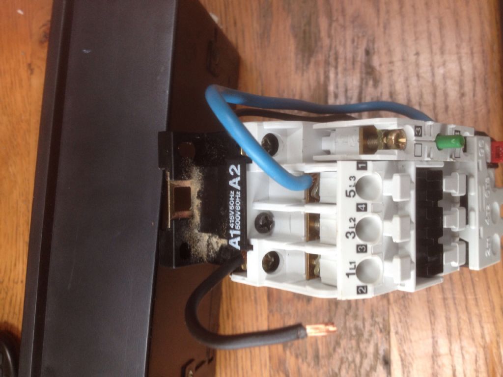
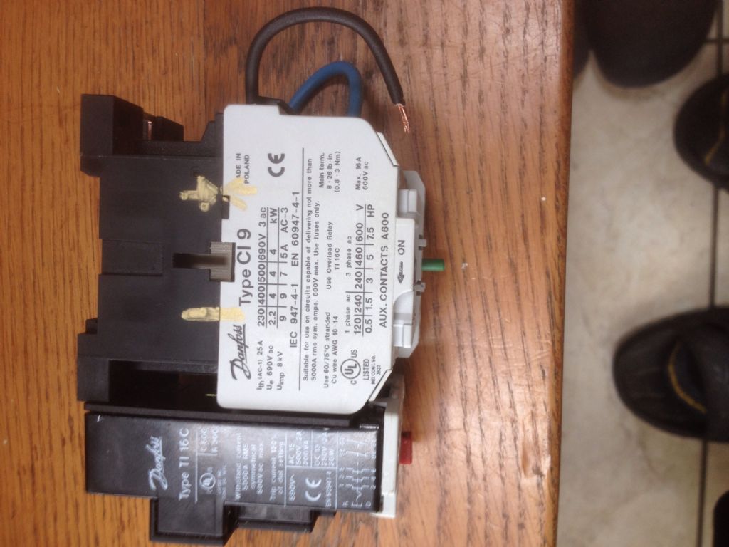
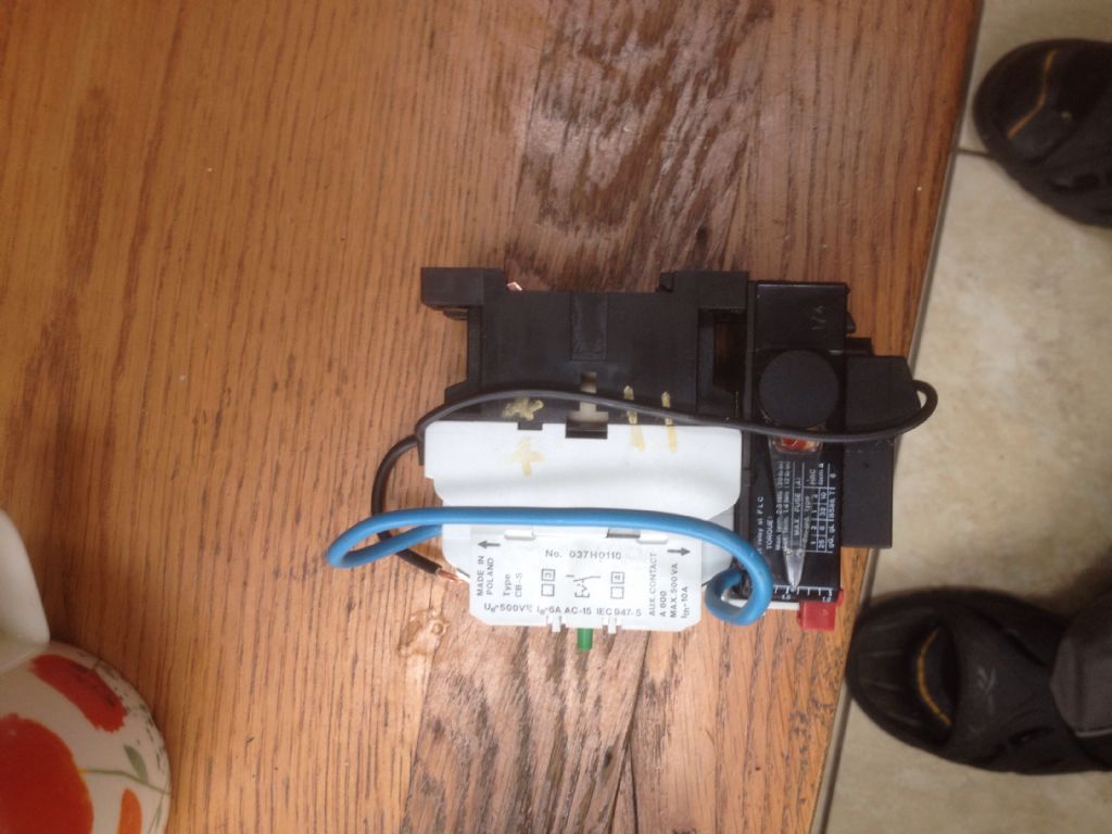
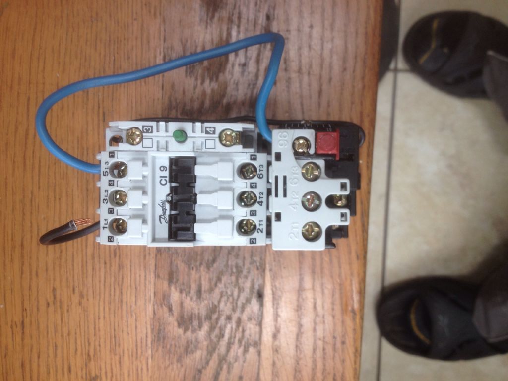
        img_2687.jpgimg_2685.jpgimg_2684.jpgThis starter came with a 3 phase bandsaw which I have now put a single phase motor in. I was told it could be wired to start the single phase motor could anyone tell me how to do this?img_2683.jpg

        #320897
        Brian Wood
        Participant
          @brianwood45127

          Hello Andy,

          The trick is to make the switch think it is receiving voltage through all three contactors.

          Wire live phase to terminal 2 and wire a loop from terminal 1 back up to terminal 3. Wire terminal 4 as the switched live on to the motor and wire the neutral phase through terminal 6 to terminal 5 which you also take on to the motor.

          It is very likely you will need to change the operating coil to one of 240 volt working, it may not develop enough magnetic pull to latch with a 440 volt coil. Your local electrical wholesaler should be able to find a suitable replacement.

          Regards Brian

          #320904
          larry Phelan
          Participant
            @larryphelan54019

            I did this years ago,with a bandsaw,which I converted to 3 phase. The starters are much the same,a 3 phase switch will handle single phase,no problem,just need to change the coil,and rewire as Brian say,s. Works a treat !!

            #320911
            Emgee
            Participant
              @emgee

              Andy

              Will the rating of the overload unit allow setting to the full load current of the single phase motor ?
              The FLC will be stamped into the motor plate and may be greater than the max o/load setting.

              Brian is correct to say loop the supply through all overload heaters but I think he has the connection details muddled.
              It is normal practise to connect the live supply to terminal L1(1) then loop from the overload term U to L2 (3).
              Connect Neutral incomer to term L3(5).
              Connect motor live to V and motor Neutral to W, both at the output from the o/load unit.
              Don't forget to connect the g/y cpc (earth) to the motor earthing point.

              Unforunately my system won't enlarge your pictures so I can see the contactor markings so do check.

              Emgee

              #320912
              Brian Sweeting 2
              Participant
                @briansweeting2

                Wiring diagram shown here…


                **LINK**

                #320916
                Ian Parkin
                Participant
                  @ianparkin39383

                  Brian

                  Why the need to do your complicated wiring?

                  The supply goes into the top contacts 1,3,5 for 3 phase or just any pair of them for single phase live and neutral

                  Certainly NOT into terminal 2 as there’s a overload fitted

                  The starter isn’t bothered about needed a load on all contacts or a load on all overload thermals

                  It would be bad practice to wire a supply through the overload first

                  Then the output to the motor comes out of 2,4,6 on the overload (next to the red button) Or the pair that you have used for a single phase pair.

                  You would have to be sure though that the coil supply’s come off the 2 pairs of contacts you have used

                  Andy

                  You will probably find that if you try to get a new coil it will cost just as much as a new direct online starter complete (screwfix do a suitable one)

                  #320923
                  Brian Wood
                  Participant
                    @brianwood45127

                    Ian,

                    Part of my problem was the poor resolution of the pictures, the 'expanded' picture is smaller than the one in the thread.

                    Brian Sweeting has put up a wiring diagram which does what I was rather clumsily trying to describe.

                    Brian

                    #320924
                    Ian Parkin
                    Participant
                      @ianparkin39383

                      Brian S

                      That wiring diagram that you linked to is nothing like Andy’s DOL

                      Though it does show the linking of wires through all poles…which there’s no reason to do so at all the starter will operate just as well with just 2 poles being used.

                      That diagram uses a separate power supply and remote start stop buttons…so nothing like Andy’s box

                      #320926
                      Brian Sweeting 2
                      Participant
                        @briansweeting2

                        Ian, the purpose of looping through all of the poles is to get better performance of the overload.

                        Did I suggest that the feed should go through the overload first?

                        Unequal loading can cause nuisance tripping.

                        Your assumption that the original poster, Andy, is unable to assimilate the schematic is rather condescending don't you think?

                        #320930
                        Ian Parkin
                        Participant
                          @ianparkin39383

                          Brian S

                          I was posting when you posted so you may have thought my comments to Brian W were for you

                          Brian W suggested that a live went to terminal 2 which COULD be either after the overload or inbetween the contactor and overload

                          I've never seen reason to connect all the thermal trips if enough current is flowing in one leg it will trip the load

                          I'd assume ( maybe wrongly) that if andy was asking if the starter was suitable for single phase 240v use on a 415 coil voltage DOL he wouldnt know how to wire it up

                          I repeat my advice to just buy a ready wired 240v dol with a overload suitable for the load and be safe

                          #320931
                          Mike Poole
                          Participant
                            @mikepoole82104

                            Some of the overloads by Danfoss have phase failure detection so need the circuit that loops through all contacts. As a matter of course I always use the loop configuration as some starters specify it and some don't but to put it in will do no harm.

                            Mike

                            #320932
                            duncan webster 1
                            Participant
                              @duncanwebster1

                              If the coil won't pull in on 240v you could put a capacitor in series to make a tuned circuit, but unless you really know about mains electrics I'd be tempted to go and buy a complete new switch, they are not that expensive. To work out what size capacitor you have to measure the inductance of the coil, so it all gets a bit involved.

                              #320934
                              Andy Sproule
                              Participant
                                @andysproule22368

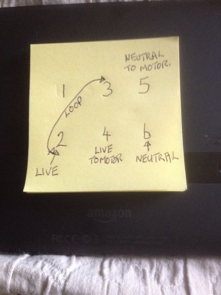
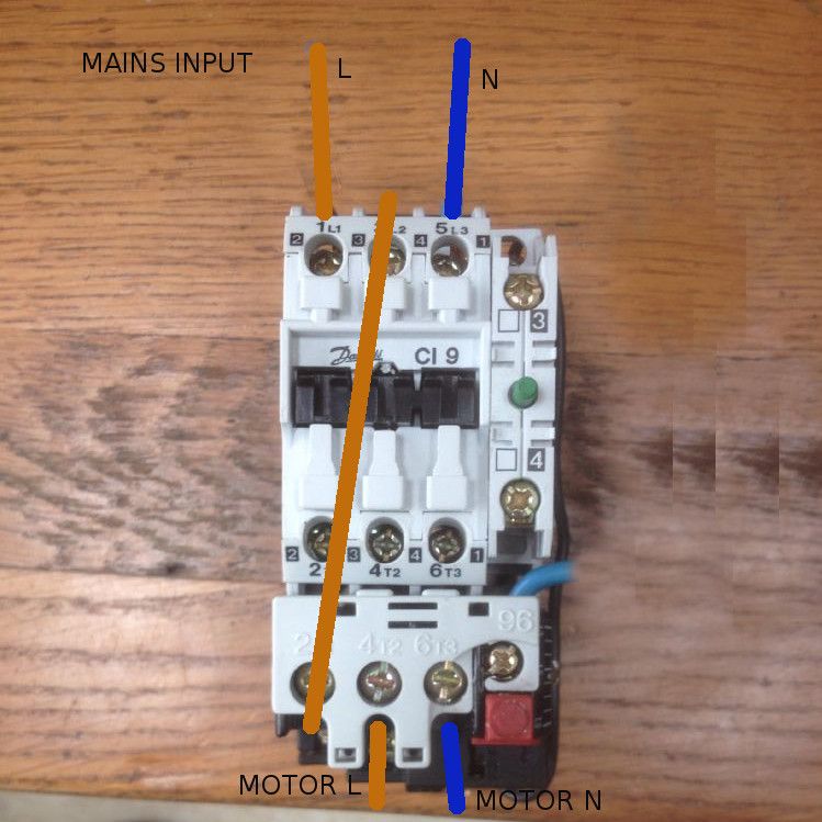
                                img_2693.jpgimg_2694.jpgHi folks thank you for all the replies.I drew out what I thought Brian Wood had said to check if I was correct and have posted a pic.Could anyone do a drawing like this but the way they think it should be it would make it totally clear to me thenimg_2696.jpg .The blue wire from 5 L3 and the black wire from A2 do they stay as they are in new wireing? Is the black wire for A1 to 1L1 done away with.

                                #320935
                                Brian Sweeting 2
                                Participant
                                  @briansweeting2

                                  Ian, thanks, I stand corrected.

                                  The reason for using all three overload contacts is because if one contact is unused there will be an imbalance across the three. Not so important with the older style overloads but the newer ones can be more sensitive. All overload manufacturers schematics will show all three contacts in use.

                                  #320948
                                  Stuart Riddell
                                  Participant
                                    @stuartriddell45006

                                    Search on ebay for a Danfoss CI9 240 volt coil, that bit with A1 & A2 on it. Change that bit and your good to go as long as the overload is the correct rating

                                    #320960
                                    Andy Sproule
                                    Participant
                                      @andysproule22368

                                      Is the sketch of the wireing correct as Brian Wood described it?The blue wire from 5 L3 and the black wire from A2 do they stay as they are in new wireing? Is the black wire for A1 to 1L1 done away with.

                                      #320973
                                      Stuart Riddell
                                      Participant
                                        @stuartriddell45006

                                        You need a live and a neutral to energise the coil which will bring in the contacts. My advice would be to get a hold of a qualified electrician to confirm the wiring but for sure if you’re working on single phase that coil needs to be changed

                                        #320979
                                        Brian Wood
                                        Participant
                                          @brianwood45127

                                          Andy,

                                          I seem to have stirred up a hornet's nest. It would actually be easier to buy a new starter switch anyway, the coil swap will cost about the same. It will be better balanced to the load as well.

                                          I don't think your interpretation of my description is correct, the loop should be brought back to the middle input terminal having been through the whole switch, you show it as a short link For the sake of clarity, the loop should be between 2 and 3 —-not 1 and 3 as you have drawn it.

                                          But be better guided by others, my advice was based on the older thermal trip MEM starter switches and modern versions are much more sophisticated.

                                          Regards Brian

                                          #320980
                                          john fletcher 1
                                          Participant
                                            @johnfletcher1

                                            The cost of a 240 volt replacement coil will be more than the cost of the starter in the first place. If you take the starter to pieces, noting what you are doing as you go, you may find that the coil windings are readily accessible or just hidden below some tape. That being so, unsolder the free end, poke a simple mandrel through the centre of the coil former and mount the former between centres on your lathe so that it runs freely. Now measure the coil resistance, then carefully remove LOTS of turns,until the NEW resistance is about 240 divided by 415 or about 60% of the original. I forgot disconnect the lathe from the mains before starting. Keep checking the resistance and if the coil has be impregnated with varnish a trip in the oven will soften the varnish but the smell is not for every one. Now reassemble the starter and very carefully connect it to the mains. The whole process should take you about half an hour, done it many times.John

                                            #321087
                                            Andy Sproule
                                            Participant
                                              @andysproule22368

                                              .John F,thank you for that I have now done it and got it back to gather with the proper resistance in the coil.But now I need clarification on the wiring

                                              #321187
                                              Andy Sproule
                                              Participant
                                                @andysproule22368

                                                img_2720.jpgimg_2715.jpgimg_2714.jpgimg_2713.jpgHigher resolution pics.Sorry to bother you all again

                                                Is the wireing in the sketch now correct?Do the wires already attached stay the same and the black wire from A1 go into 1L1?img_2712.jpg

                                                #321203
                                                SillyOldDuffer
                                                Moderator
                                                  @sillyoldduffer

                                                  Andy,

                                                  I hope someone else will confirm because my experience is limited in this area!

                                                  I believe that the circuit posted by Brian is correct and it is necessary to use all 3 thermal cut-outs. That's because. if I understand the blurb correctly, the CI9 detects single phase dropouts as well as overloads.

                                                  Ignoring the wiring that powers the contactor itself, I think it should look like this:

                                                  contactor.jpg

                                                  Happy to be told I'm wrong. If I were you I'd test it by wiring a table lamp to the motor L and N with a 3A plug on the input side. If it works the lamp OK, move on to the motor .

                                                  Dave

                                                  #321209
                                                  Brian Sweeting 2
                                                  Participant
                                                    @briansweeting2

                                                    SOD, yes that is correct, good picture.

                                                    #321214
                                                    SillyOldDuffer
                                                    Moderator
                                                      @sillyoldduffer
                                                      Posted by Brian Sweeting on 12/10/2017 19:46:21:

                                                      SOD, yes that is correct, …

                                                      Phew! Thanks Brian, I had my fingers crossed.

                                                      Dave

                                                    Viewing 25 posts - 1 through 25 (of 39 total)
                                                    • Please log in to reply to this topic. Registering is free and easy using the links on the menu at the top of this page.

                                                    Advert

                                                    Latest Replies

                                                    Home Forums General Questions Topics

                                                    Viewing 25 topics - 1 through 25 (of 25 total)
                                                    Viewing 25 topics - 1 through 25 (of 25 total)

                                                    View full reply list.

                                                    Advert

                                                    Newsletter Sign-up