Start of Tom Senior refurbishment.

Advert

Start of Tom Senior refurbishment.

Home Forums Manual machine tools Start of Tom Senior refurbishment.

Viewing 21 posts - 26 through 46 (of 46 total)
  • Author
    Posts
  • #423661
    old mart
    Participant
      @oldmart

      I took the camera into the museum today for the pics of the quill bearing outrigger and the nearly finished spindle. The spindle halves are awaiting the arrival of the Loctite 620. I had a rare flash of inspiration today regarding the undersize drawbar hole in the spindle. I looked in our box of reamers and found a sharp 7/16" hand reamer. I reamed from both ends of the top half of the spindle and was left with about 3" in the middle to do. I turned down 1/2" of the reamer to 8mm and found some 1/2" AF hexagon steel bar. I turned about 5" of the 6" length I cut to 11mm diameter, and drilled an 8mm hole in it. The reamer was silver soldered to the extension and the whole bore is now 7/16".

      I will be sticking to my self extracting design with a bronze nut about 1" long with a 1/4" thick flange at the lower end loctited about 3/4" from the bottom of the drawbar. The flange will bear against the end of the top half of the spindle, (see the picture.

      Advert
      #423713
      Simon Williams 3
      Participant
        @simonwilliams3

        Hi again, serial number on mine is V3485, making it 1974 vintage, Your s/n at 2961 is a whole lot earlier, does this mean that Mr Senior decided to ditch needle rollers for the driven pulley and go to a bronze bush as an improvement? It does seem to indicate that my assumption that needle rollers and a spline drive is later is wrong!

        Interesting stuff, what!

        Like the spindle/quill.

        Rgds Simon

        Keep taking the tablets (out to the shed).

        #423756
        old mart
        Participant
          @oldmart

          Miles Hellon's thread on the Tom Senior contains serial numbers against dates which I used to guess our machines vintage. As I mentioned earlier, there is no build stamp on the head to match it with the rest of the machine. As the head is a major sub assembly at least as complicated as the rest of the machine, it may well have been a completely separate build.

          #424235
          old mart
          Participant
            @oldmart

            The spindle is now one piece using the Loctite 620. The quill and outrigger lower bearing were done up tight and Rod drilled and tapped for a 2BA grub screw to make sure nothing comes loose in the future, unless we want it to. I got a 400mm length of 7/16" 431 stainless steel for the drawbar and singlepointed the ends 7/16 UNF. I also reduced the centre part with a 0.005" cut using an insert designed for stainless, which cut beautifully. The stainless grade insets I have are halfway in sharpness between the blunt steel and the sharp aluminium type. The drawbar was too good a fit in the spindle and needed a little clearance.

            I had some trouble with the bronze threaded extractor collar. I had to screw it about 1 3/8" along the drawbar and it started well with loctitite 290, but only got halfway. I had to use a hot air gun to unscrew it and start again using the 620, which just succeeded. It was also getting tight over the last 1/4". I think it must be the viscosity of the Loctite causing local heating when a long length of thread is screwed up.

            #425405
            old mart
            Participant
              @oldmart

              I built up the spindle in the quill the other day. I gradually tightened the bearing adjusting nut, but was unsure if I had reached the point where the preload started. So I slackened off the nut and pressed the spindle to slacken off the bearings. I then set the quill on vee blocks on the bed of the drill mill and clamped it lightly with card between the quill and vee blocks and clamps. With it fixed, it was easy to creep up on the point of bearing contact and add about 10 degrees of preload.

              The head is fitted on the mill and we built it up in situ. With the quill in place and locked in the up position, we figured out by trial and error how to tension the return spring. You fit the pinion shaft and connect the outer end of the spring, then carefully slide the shaft out until it just clears the rack on the quill. You can then wind it up until the od of the coils just allow the cover plate to be fitted.

              I have removed the needle roller bearings from the pulley housing, as they will be easier to clean, and I want to replace the button oiler with a grease nipple. There are three sizes of button oilers on this mill, 3/16", 1/4" and 5/16".

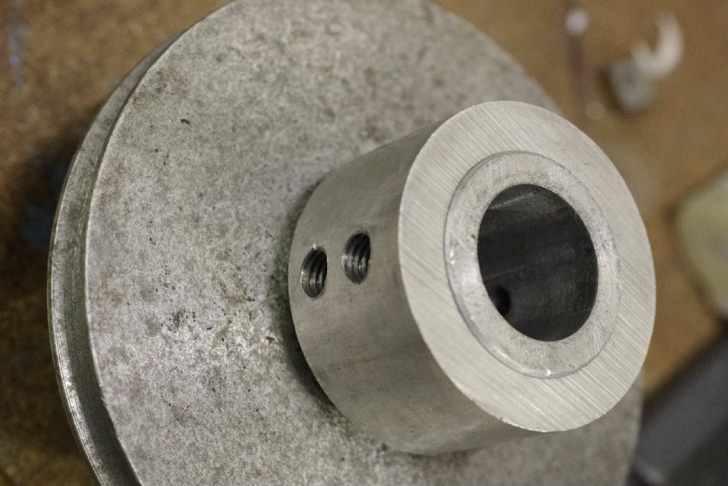
              I had to bore out the end of the motor pulley, as the current motors have a larger 24mm shaft. It couldn't be a simple job as the smallest pulley was only about 25mm at the bottom of the vee. I turned a steel bar down and pressed it onto the small end and used that as a mandrel to bore the other end. The finished wall thickness of the bored end was only 1/4", so I have fitted a collar, so the grub screws have a decent length of thread.

              #425814
              old mart
              Participant
                @oldmart

                The head is looking nice now that it is finished except for the motor mounting. Mike fitted the bearings back in the pulley housing and fitted a grease nipple in place on the original button oiler. We don't want anyone oiling the needle rollers. I milled a second flat on the splined pulley holder, so that both of the grub screws in the pulley have something to grip on. I do wonder at the design, the whole pulley and motor assembly is held onto the head with four 2BA screws. The quill spindle drive splines are lubricated with a sparing amount of moly grease applied using a toothbrush. Otherwise, ordinary lithium grease is used for taper rollers and needle rollers. Everything else has slideway oil, except for the leadscrews, which have spray motorcycle chain gease. The quill spring causes a clang if it is let go, so I am getting some 7mm diameter o ring material to make a soft stop. I had put a step in the outrigger where it screws into the quill, for no particular reason when I turned it, and the bump stop will sit there.

                #425975
                old mart
                Participant
                  @oldmart

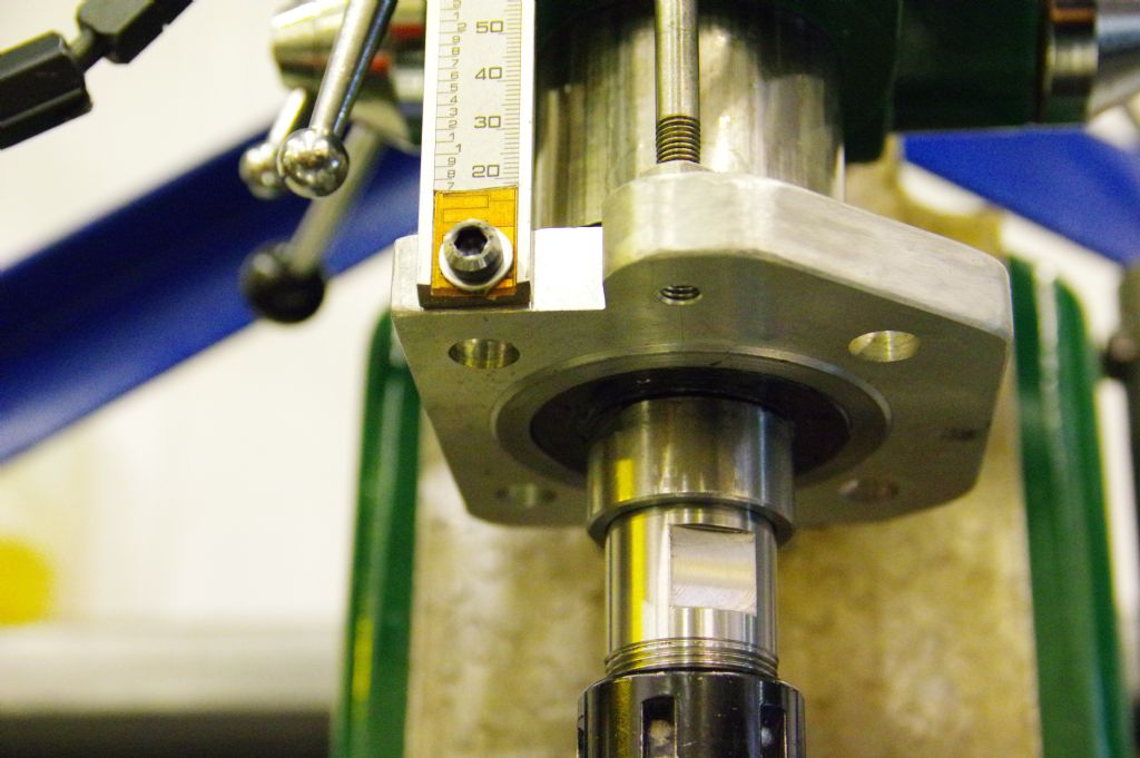
                  I have decided to make a totally new motor mounting plate out of a 1/2" thick piece of 6086 aluminium, 250 x 153mm, as the modern mounts on the motors are quite different from the original ones. This is slightly thinner than the old one, but stronger as it is not a casting. The alternative was a 6mm thick plate as an adaptor, which was not thick enough for threading. The drawbar is fitted which is self extracting with its bronze bottom nut, and brass washer, half nut, main long nut and a second half nut at the top. Because the drawbar nut is a larger spanner size, the hole in the pulley housing which the chrome drawbar cover fitted has had to be bored out in the mill. I will have to look for something to make a cover out of, some nylon bar might do.

                  #426413
                  old mart
                  Participant
                    @oldmart

                    Today, I thought I ought to check whether my conversion to R8 has been up to scratch. With the er25 collet holder nice and tight in the spindle, using Vertex and Cutwel collets and trying 6,10,and 16mm shank endmills, the runout was 0.0003" tir on each size. Then I tried out my Osborn Titanic II, with 16mm, and 1/4" shank endmills and got 0.0005" tir on both. All the careful setting up of the spindle parts and the lower bearing outrigger has paid off. I had been worrying about how the two halves of the spindle would run, especially as the SKF lower taper roller and the Timken upper taper roller ran on different halves of the spindle. One drill chuck runs from 0.002" to 0.004" and the other larger 16mm one runs 0.004" @ 16mm, dropping nicely down to 0.001" at 6mm. The self extraction with the drawbar works very well, just 1/4 turn between pulling and pushing.

                    Not everything is quite as fortunate as that, however, I found out that my boring out of the motor pulley isn't deep enough, so it has to go back up on its mandrel for another 14mm of bore.

                    #427475
                    old mart
                    Participant
                      @oldmart

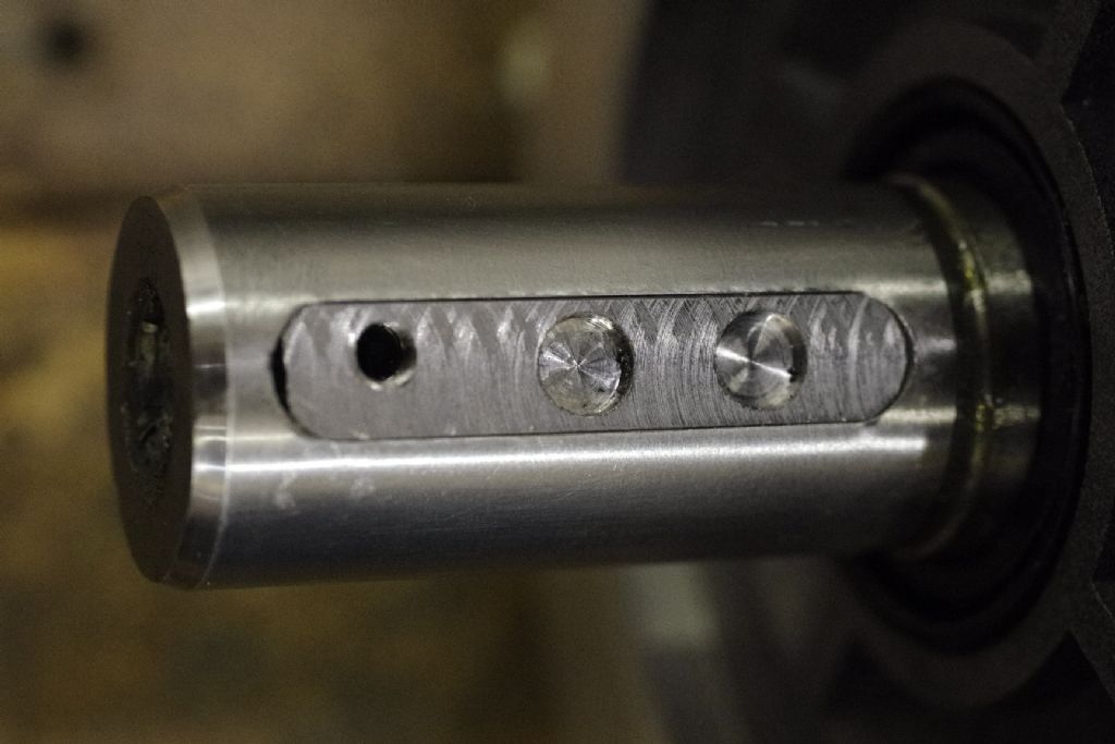
                      _igp2440.jpgWe aligned the pulleys the other day, the motor had to be temporarily fitted. I milled the motor shaft woodruff key down, so it was flush with the shaft od. When the pulleys were in line the grubs crews were tightened down onto the key to leave witness marks. The key was then removed and a 6mm end cutting mill was used to produce two 1.5mm deep holes in line with the witness marks. The 8mm grub screws had their tips turned to 6mm to locate in the key for a more secure drive. We don't have any means of making a key slot in the pulley, and the original wall thickness after boring it to 24mm was marginal. I had to drill and tap the key to get it out, that's what the threaded hole is for

                      _igp2439.jpg

                      #427950
                      old mart
                      Participant
                        @oldmart

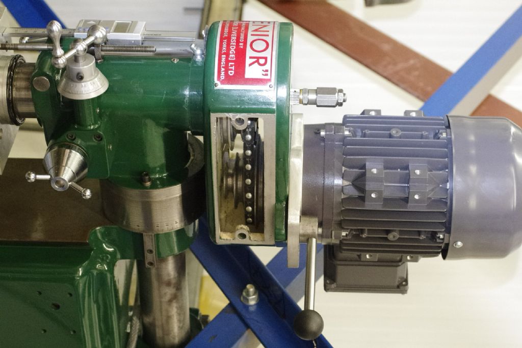
                        The motor is mounted, not without slight problems. I bought a metre of the 10mm link belt, similar to Fenner nut link. Judging from the length of the old belt, I got two from the metre length, one slightly longer than the other. After fitting the longer one, I recon that the shorter one might just fit too. Fitting the link belt caused a problem straight away, we couldn't get it between the housing and the largest pulley on the spindle. I had thoughts of grinding away at the tight area in the housing, but tried an easier solution first. Taking the pulley off and reducing the top flange of the largest vee. I took off 0.042" off the diameter, and rounded the edges, and the belt just fitted with a little help. The link belts must be a bit deeper than a plain one.

                        #428063
                        old mart
                        Participant
                          @oldmart

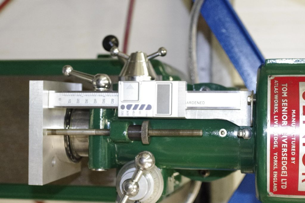
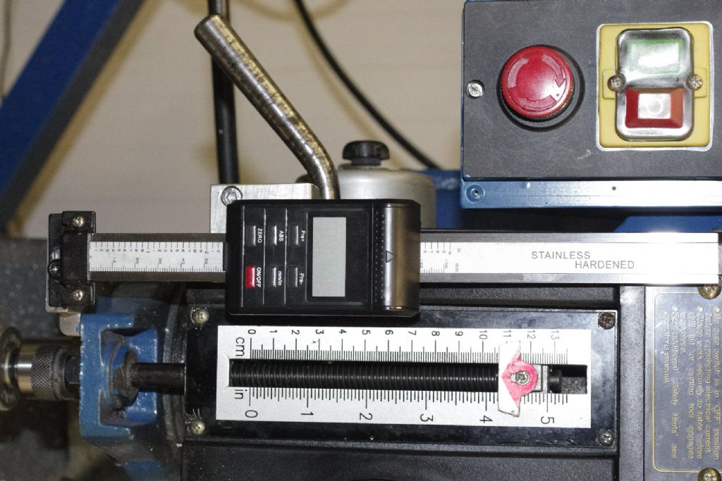
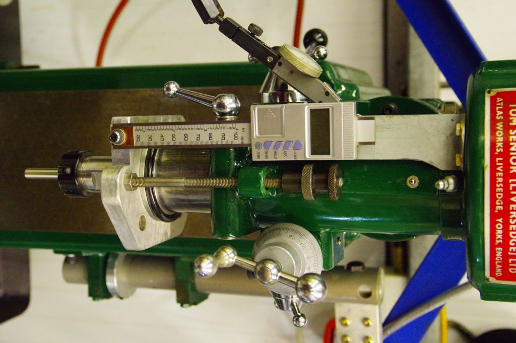
                          _igp2444.jpg_igp2443.jpg_igp2443.jpg_igp2442.jpgThe DRO for the quill that I bought from Arc was 1/4" wider than the old one on the drill mill. Not much, but it was worth swopping them as the TS is extremely limited for space between the lock and the depth stop. The pictures show the new DRO fitted to the drill mill and early stages of fitting the old one to the TS. Mike made a lever to lock the belt tension and we have finished fitting the motor.

                          We intend to make covers for the belt in 6mm polycarbonate for easy checking of the belt position. Any suggestions as how to fix them would be gratefully received.

                          _igp2441.jpg

                          #428778
                          old mart
                          Participant
                            @oldmart

                            The digital quill depth reader has been finished, I had to cut about 1/2" off one end and it was more of a challenge than I thought it would be. It wore out two new Eclipse junior hacksaw blades, and then I thought it would be a good idea to drill a hole in the bottom end. I used a new solid carbide 7.3mm YG Dream for hardsteel, it did the job, but any hss or even cobalt would have failed completely. The aluminium block in the picture looks a lot different now. The stroke of the quill is exactly 2.5". Mike made a nice cap for the projecting end of the drawbar out of two pieces of aluminium fitted together as we couldn't find anything to make it out of one piece.

                            The motor will have to come off and be turned round, as the wiring box comes very close to the bracing for the mezzanine, especially if the head is tilted.

                            Edited By old mart on 12/09/2019 20:35:02

                            Edited By old mart on 12/09/2019 20:43:38

                            #433003
                            old mart
                            Participant
                              @oldmart

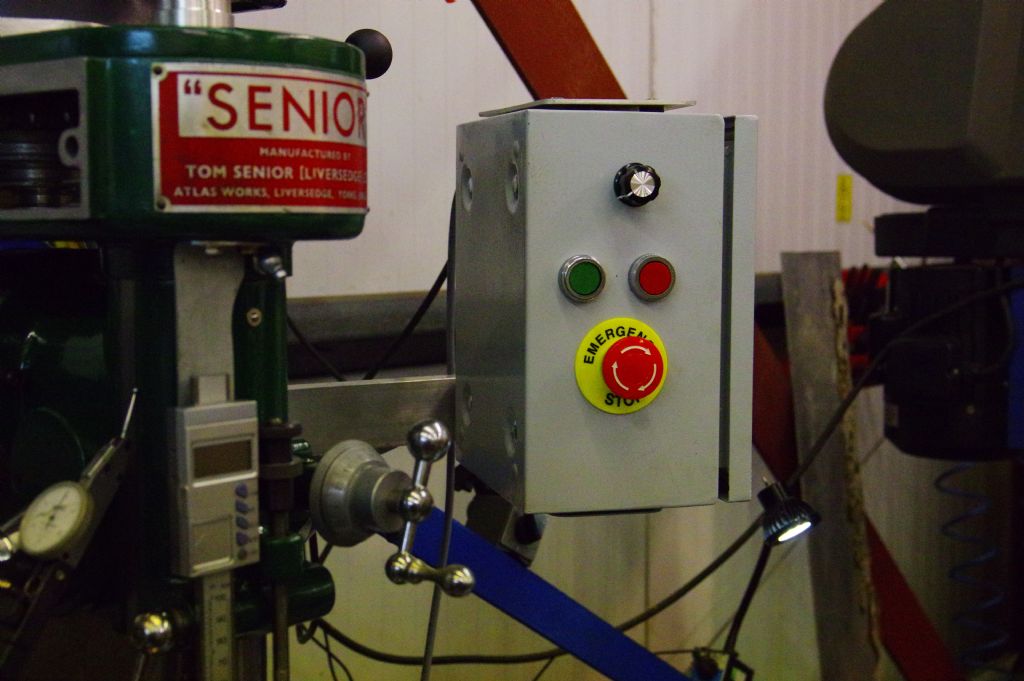
                              I have pretty well finished the electrics, except for making a bracket for the second emergency stop button. When I checked the wiring continuity with a meter, there was an inconsistency in the contact resistance in the regular stop button and one of the emergency stop buttons. They are in series, all the inverter controls are remote. The switches are Chinese and there is nothing obviously wrong with their functioning. Not having any Servisol switch lubricant, I gave each switch a good dowsing in AC90 which is similar to WD40. Now they work as they should, and I did the same to the start switch, just in case.

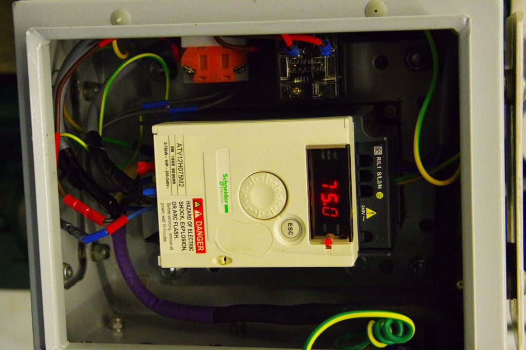
                              The inverter is a Schneider ATV12 0.75 Kw and the motor is a TEC three phase 0.75 KW six pole. I bought them from The Inverter Drive Supermarket and chose one of the inverters that benefited from their quick start guides pdf which Rod printed out. It took me about an hour to get the programming to my satisfaction, it would taken a year without the QSG. I have the frequencies running from 25 to 75 Hz.

                              The link belt turned out to be two links too long and it rubbed the housing in top speed pulley configuration, and the spindle is overheating. It still ran hot after slight slackening, and if one more adjustment does not do the trick without over slackening the bearings, I will have to assume that I have overpacked with the grease, and will have to remove the spindle from the quill to remove some. I fitted a double lip oil seal with the same id as the spindle nose diameter without the garter spring, and bored the bearing housing where the seal sits a couple of thou oversize, so it will not be too hard to push out when or if the spindle is removed.

                              I will post some more pics next week.

                              #433584
                              old mart
                              Participant
                                @oldmart

                                I still had overheating problems with the spindle bearings today. Two possibilities are common when overheating is present, too much preload or overpacked bearings. I removed the spindle from the quill to confirm that I hadn't overpacked, and I adjusted the bearings for zero slack, but no preload. This was done with the quill lightly clamped down onto vee blocks, and a dti to check axial float. Back together at 3000 rpm, the overheating was exactly the same. A clue as to the culprit was the fact that the top bearing was not getting hot. The oil seal which was fitted to prevent contamination of the lower bearing was to blame. It is a double lipped seal with the inner size the same as the od of the spindle nose. I had removed the garter spring and greased it before fitting it. I cut off the inner seal lip leaving only the outer lip. This didn't matter as the seal was not there to hold the grease in, but to keep the bearings clean. No more overheating.

                                #433747
                                old mart
                                Participant
                                  @oldmart

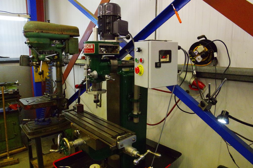
                                  imgp0938.jpgA few more pictures, the machine is close to cutting metal.imgp0935.jpg

                                  #433752
                                  old mart
                                  Participant
                                    @oldmart

                                    imgp0944.jpgimgp0942.jpgimgp0936.jpgI have been having trouble with the internet, and, just when I want to put more photos on this forum, the site is acting up. Never mind, Ill have another go.imgp0937.jpg

                                    #433760
                                    old mart
                                    Participant
                                      @oldmart

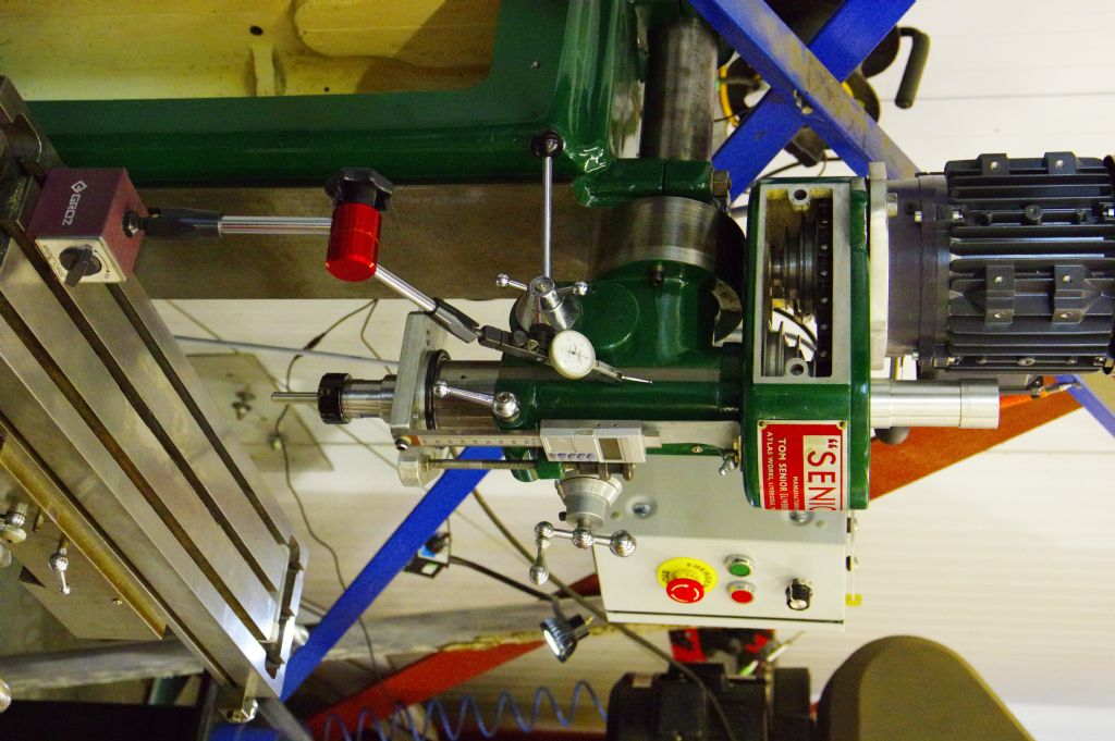
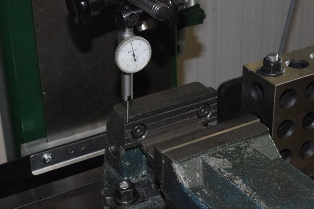
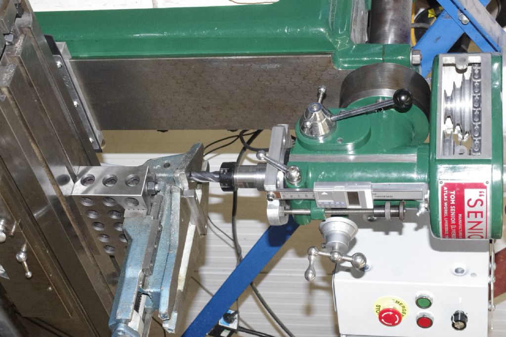
                                      The second picture in todays series shows another way of tramming the mill. There is a ground surface about 6" long on the left side of the head, and I put a lever dti on the bed and used the knee to run up and down it. The VFD set between 25 and 75 Hz results in a speed range using the pulleys of 174rpm to 2900 rpm. The view of the underside of the quill shows the oil seal which caused me so much hassle.

                                      I have one of the 100mm Bison vises up on the bed with a new key for the 1/2" slots, I haven't checked the alignment yet, it may need a skim of the rear of the key.

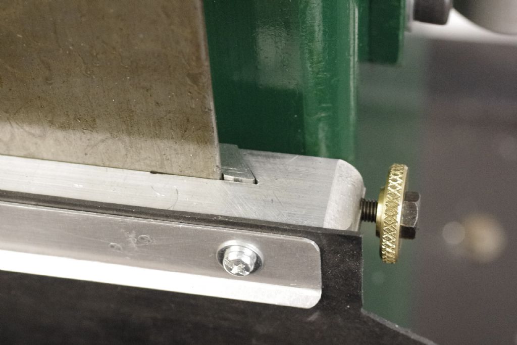
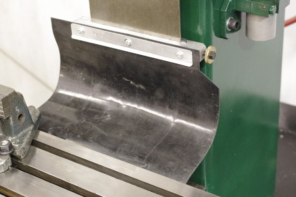
                                      The new rubber sheet to protect the rear of the X and Y axes is nearly complete and the polycarbonate guards are at an early stage.

                                      I bought a set of the tee slot clamping nuts, studs, etc and wasn't happy with the looseness of the 3/8" tees in the slots. The nuts have been tapped out for 10mm helicoils, a metre of 10mm studding will be cut up and new tee nuts are being made for a better fit, in addition to the half dozen 10 mm ones we already had.

                                      #433827
                                      old mart
                                      Participant
                                        @oldmart

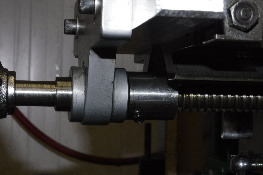
                                        I have measured the X axis travel after adding the extra thread to the leadscrew and fitting two nuts for backlash reduction. It is 18 5/8" for the longer bed. The travel is not symmetrical, it moves two inches more to the right than to the left. I don't think there is any easy way of increasing the travel and am pleased that it is about the same as before the modifications. The next mod to the X axis will be a round 5" wheel at each end.

                                        #433968
                                        old mart
                                        Participant
                                          @oldmart

                                          _igp2468.jpg_igp2467.jpg_igp2464.jpgI have cut some metal on the mill at last.

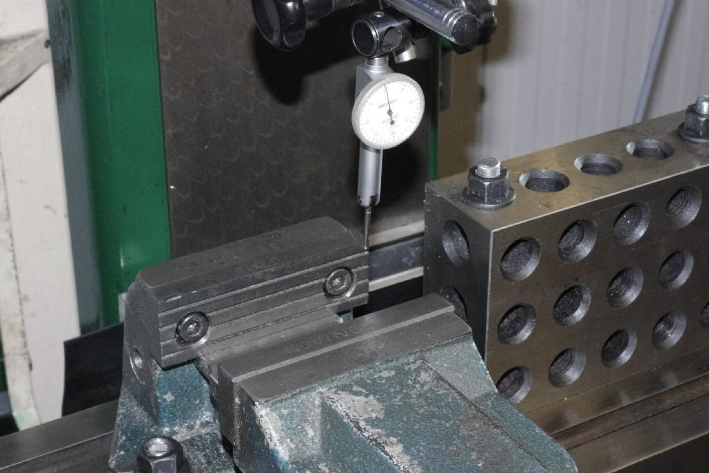
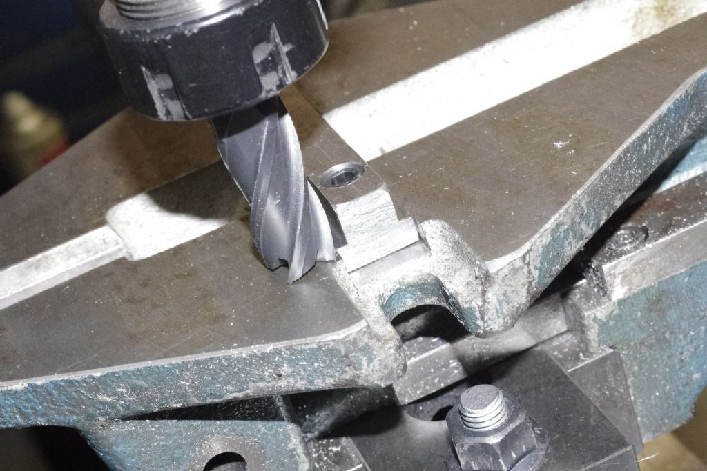
                                          The slots in the bed are 1/2" while the drill mill slots are 5/8". I used the DM to rough out a replacement key for one of the 100mm Bison vises. It had a run across the rear jaw of 0.0015" which is understandable. The pictures show how I got the vise dead on with the X axis, the amount of actual milling amounted to a skim of about 0.002" climb milling on the rear of the key.


                                          _igp2463.jpg


                                          Edited By old mart on 19/10/2019 19:09:19

                                          #434691
                                          old mart
                                          Participant
                                            @oldmart

                                            _igp2479.jpg_igp2481.jpgSome more pics of the progress. I fitted the rubber swarf guard which Mike has made. It is a rather poor design which has to be moved up and down when the knee and Y axis are moved, there is really no alternative. The other one has the spindle speeds, please tilt your heads to view._igp2480.jpg

                                            #439517
                                            old mart
                                            Participant
                                              @oldmart

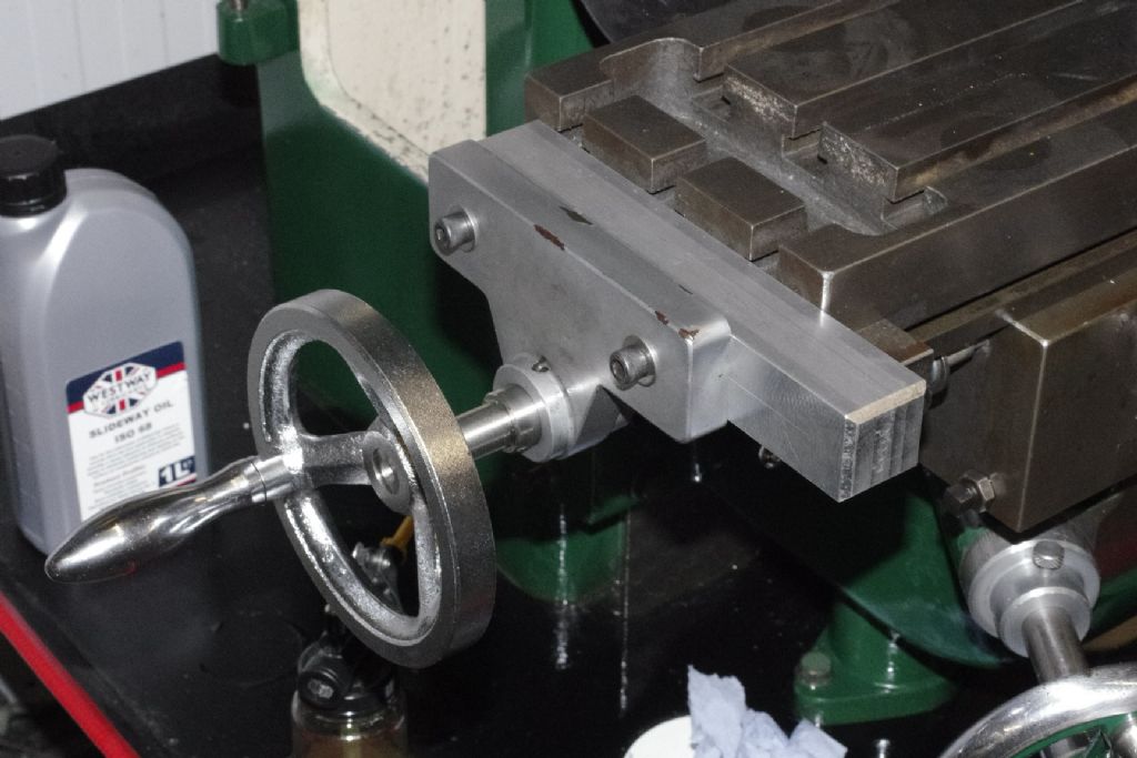
                                              _igp2504.jpgWe pretty well finished putting a handle on the left end of the X axis leadscrew. The aluminium spacer needs to be cut a little shorter._igp2503.jpg

                                            Viewing 21 posts - 26 through 46 (of 46 total)
                                            • Please log in to reply to this topic. Registering is free and easy using the links on the menu at the top of this page.

                                            Advert

                                            Latest Replies

                                            Home Forums Manual machine tools Topics

                                            Viewing 25 topics - 1 through 25 (of 25 total)
                                            Viewing 25 topics - 1 through 25 (of 25 total)

                                            View full reply list.

                                            Advert

                                            Newsletter Sign-up