I've been busy taking measurements and drawing graphs. All dimensions in millimetres.
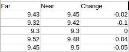
These tables are roughly equivalent to Iain's change over distance. This one shows dimensions when the work is unsupported:

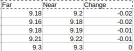
And this is when the work is supported by a tailstock:

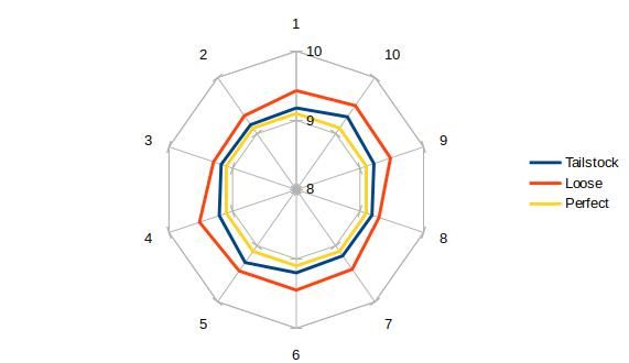
Graphically the difference looks like:

The tailstock supported cut is closer in shape and dimensions to theoretical perfection than the unsupported cut.
The change of cut depth when the work is unsupported is up to 5 times worse than when the work is supported. In both cases there is evidence of a taper.
Next I lathed the ends off the test piece so that I could measure the widths of the flats, ie the legth of one side of the pentagon.

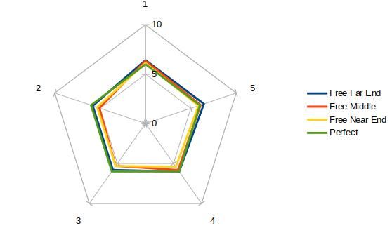
The figures reveal much more variation in the unsupported ('free' pentagon, than it's Tailstock supported equivalent.
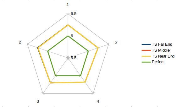
This graph overlays the shape of the pentagon over about 8mm length of rod. (I wish I'd taken longer cuts!) You can see that although the table holds the 72° angles the dimensions of the pentagon change. There's a hint of twist too, though that might be a coincidence.

The equivalent graph when the work is supported by the tailstock is neater. The lines almost overlap showing that the pentagon is dimensionally stable and there is no hint of twisting. Only the blue far end edges out on axis 2, this being consistent with the slight taper noted earlier.

Conclusions.
Iain's Original Post expressed a concern about the run-out of his Rotary Table, which is a Warco HV6 like mine. He found 0.14mm on a rod 50mm out from his chuck.
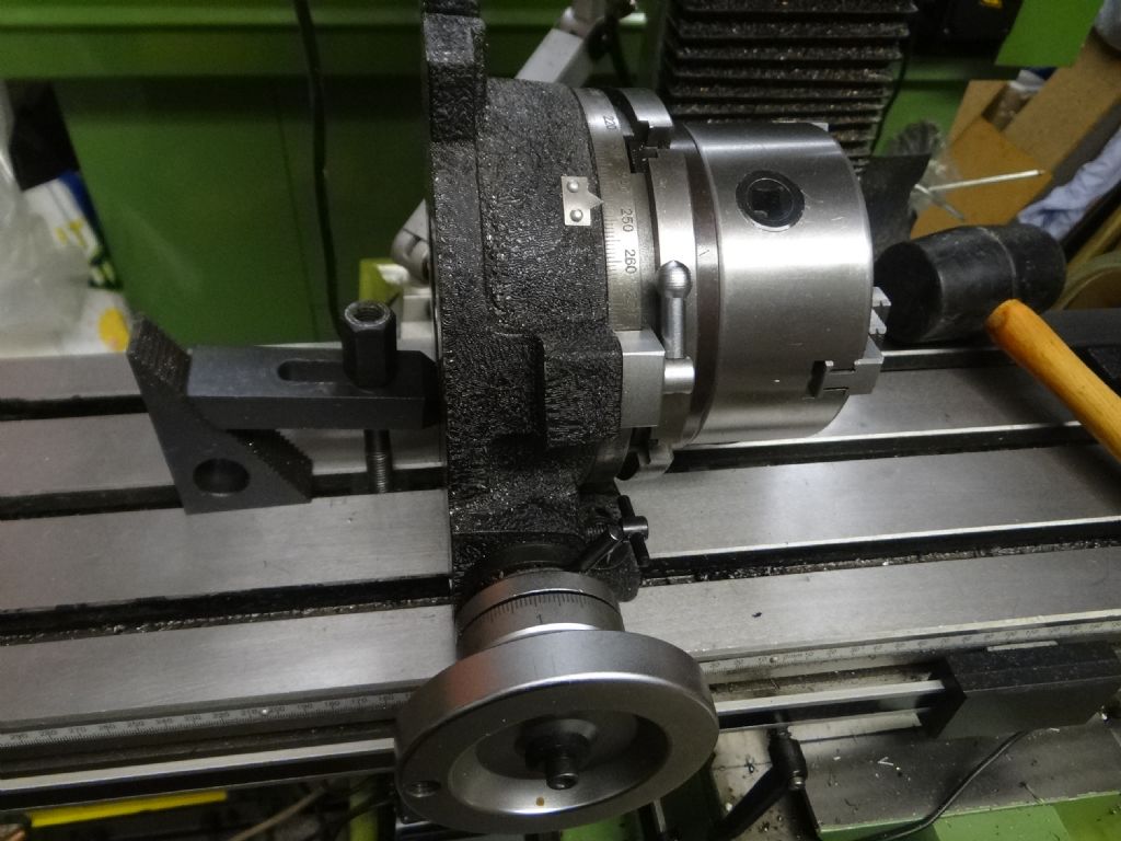
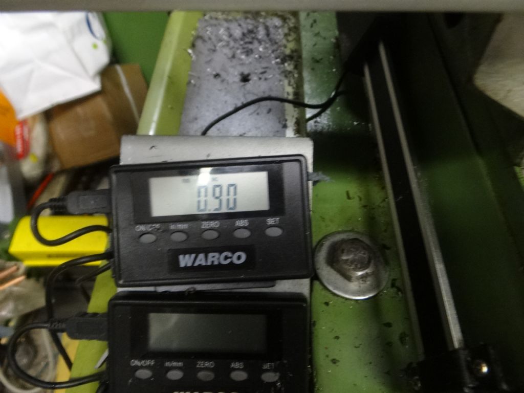
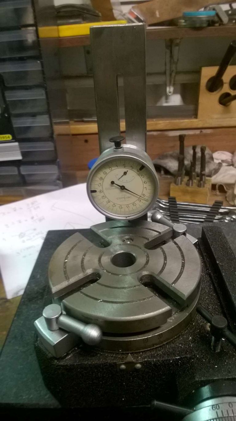
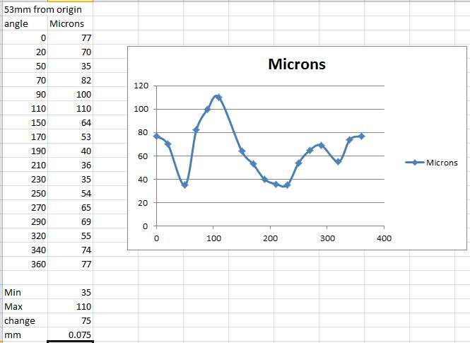
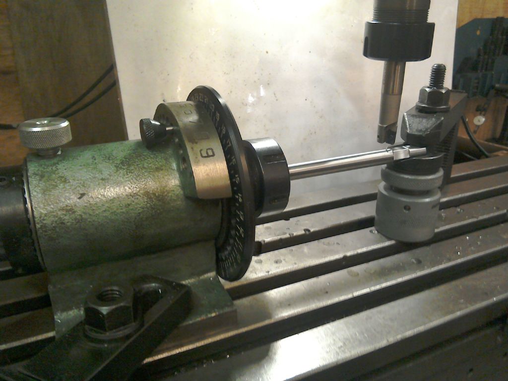
My HV6 has a run-out measured at the centre hole of the table of less than 0.02mm. With 200mm of 10mm diameter rod protruding from a 6" chuck, I found run-out of 0.2mm at the end of the rod. Tightening the rotary table clamps reduced this to less than 0.1mm. I suggest this is comparable to the error in Iain's set-up.
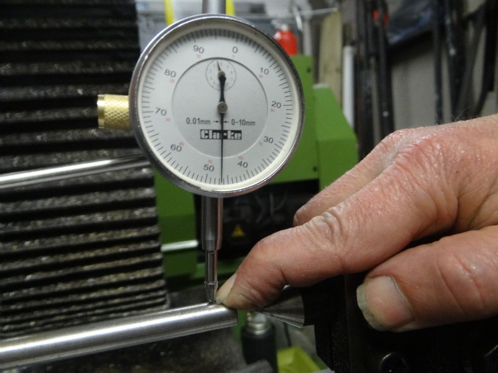
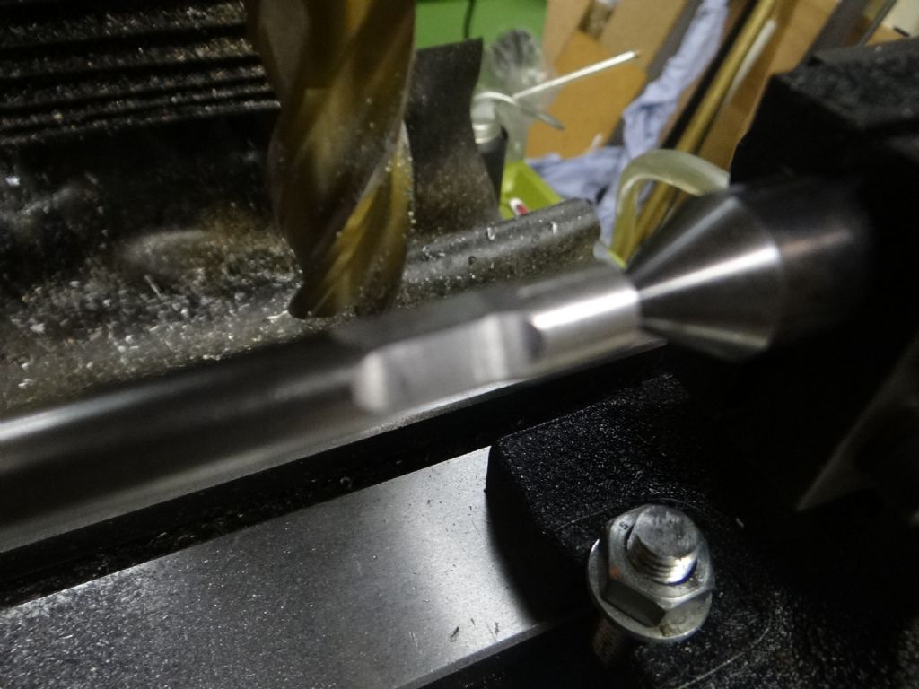
I was able to bend my rod with my finger by 0.53mm; this is certainly less force than can be applied by the milling machine and it's lead-screws . When cutting the rod without benefit of a tailstock the end of the rod vibrated by about 2mm at the end and there was chatter.
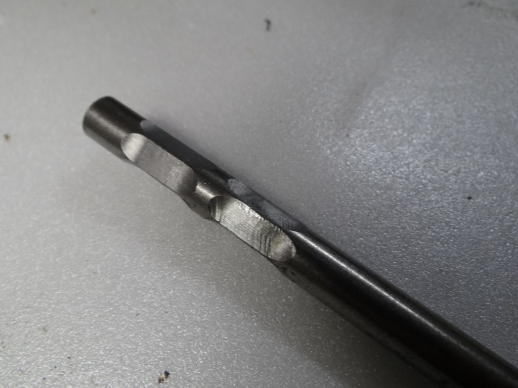
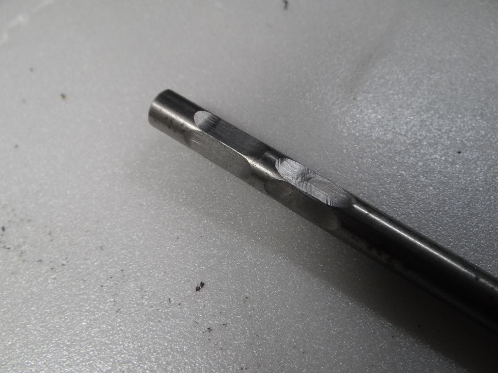
The figures show that the dimensions of unsupported cuts were about 4 times less accurate compared with those done when the work was supported. The figures also show that the dimensional changes of unsupported cuts are inconsistent, presumably because the rod is acting as a spring, releasing energy whenever it can. The photographs confirm that supported cuts are better, not only in terms of dimensions but also the finish. This confirms the classic advice that care should be taken to ensure that work be held as rigidly as possible.
Though not as bad as I expected, I was unable to make a good pentagon without a tailstock. As my 'run-out' was similar to Iain's, I suggest my results show that his poor results are more to do with not sufficiently supporting the work than a defective table.
Is my table more accurate than Iain's? We don't know. My base run-out measurement was taken from the centre hole with the table flat, which is as good as it can be. Iain measured his run-out from the work, which will amplify any error, not only in the table, but also in the way it was configured.
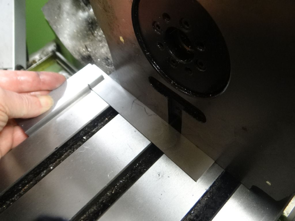
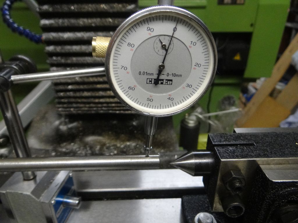
In that respect it's worth considering all the possible sources of error; I used a set-square to align the table; I used a DTI to align the tailstock and confirm it was working; I clamped the table locks before taking a cut; I clamped the unused mill-axes before taking a cut; and I used the fattest milling cutter I own as close to the spindle as I could get. Even so I look forward to someone pointing out where I went wrong. (Not least me being cack-handed.)
I haven't tried cutting a pentagon to see what happens with the rod deliberately shimmed in the chuck to artificially create a significant run-out error. Perhaps Thursday…
Cheers,
Dave
Edit: pesky smilies!
Edited By SillyOldDuffer on 28/03/2017 16:43:12
larry Phelan.


