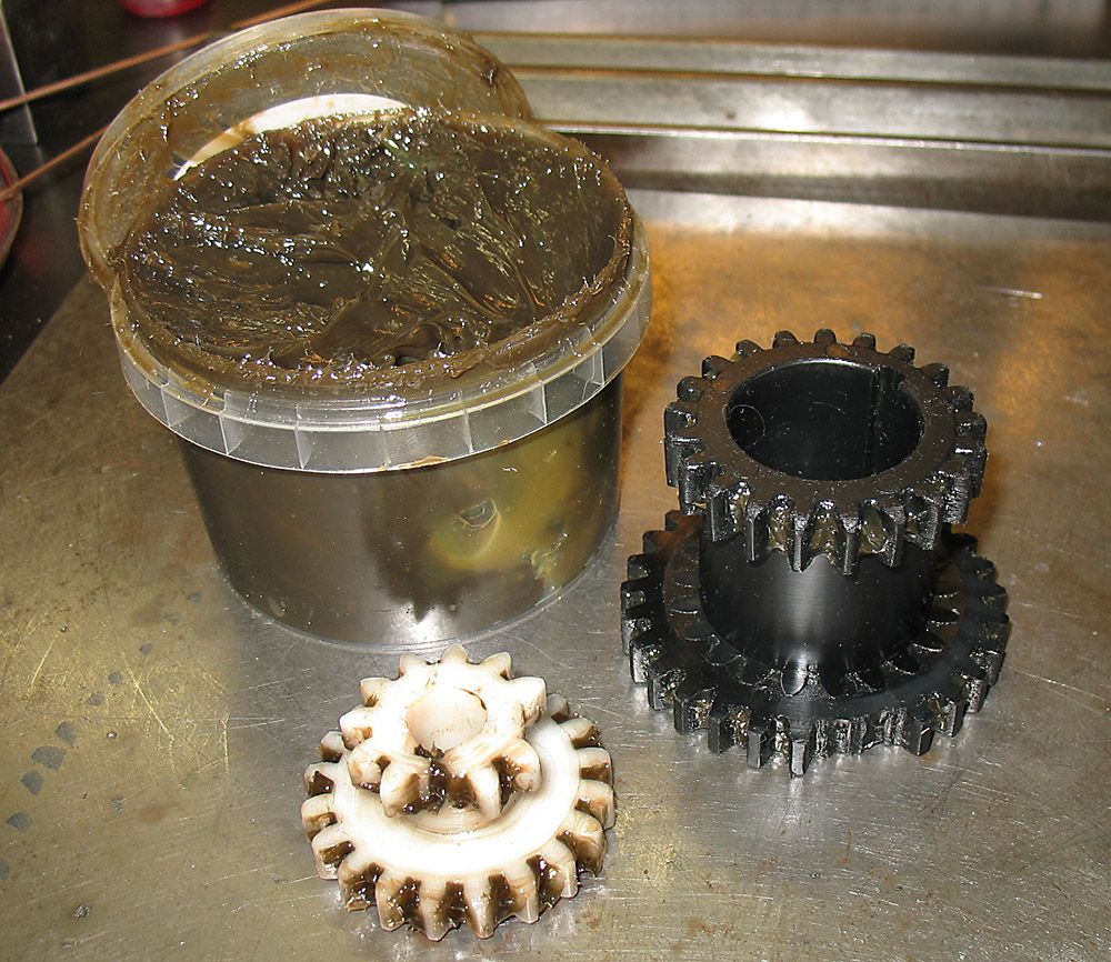
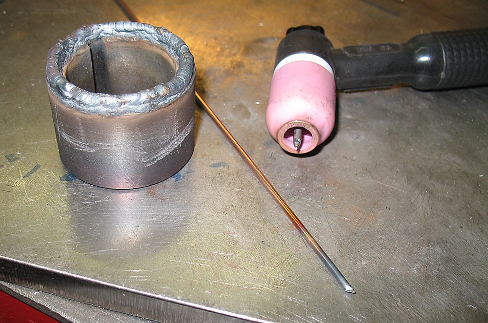
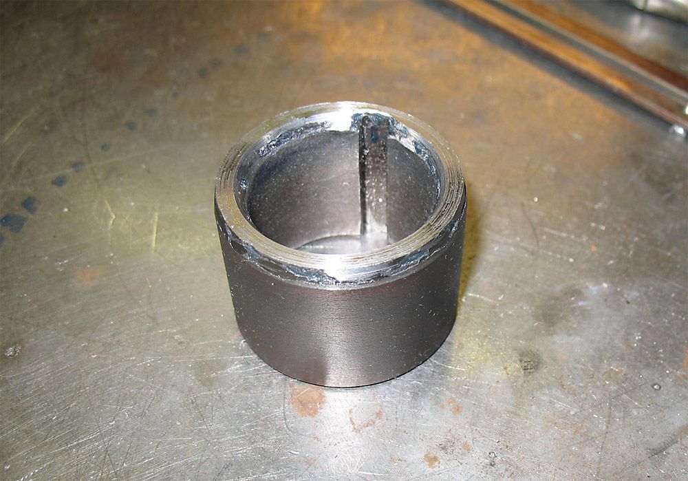
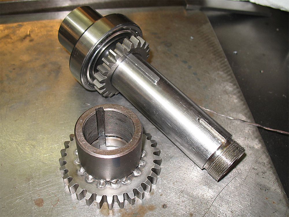
The next step was to join the spacer to the larger of the two main gears. I temporarily slid the spacer and larger gear onto the main spindle to line them up, and tacked them together. I then removed them from the spindle to finish the rest of the weld-up on the bench. You will see in the photo that I elected for a series of deep, spotting welds around the circumference of the spacer. I chose for this approach instead of a continuous weld seam in order to avoid potential distortion. I’m certain it is strong enough for purpose. The welds did pull the gear ever so slightly out of line, but a very light skimming cut with the boring bar on the lathe allowed the welded-up pair to slide back over the spindle.

The three-piece stack having been converted to a two-piece stack with the topmost gear driving the shaft through the welded-on spacer, the short spindle key was no longer an issue. So I proceeded to reassemble the transmission.
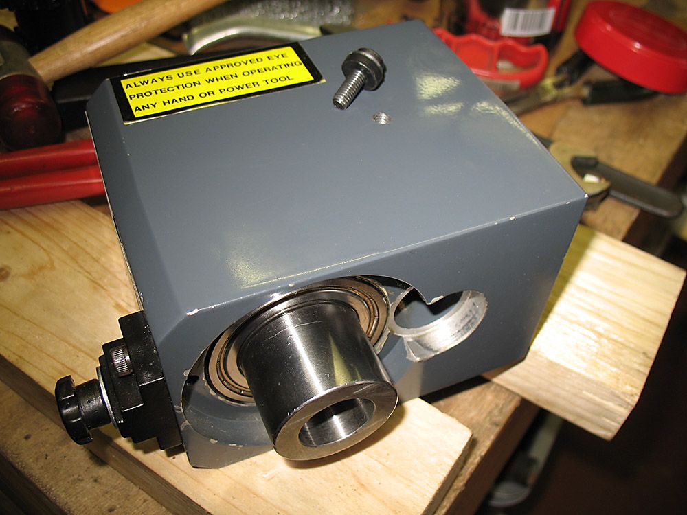
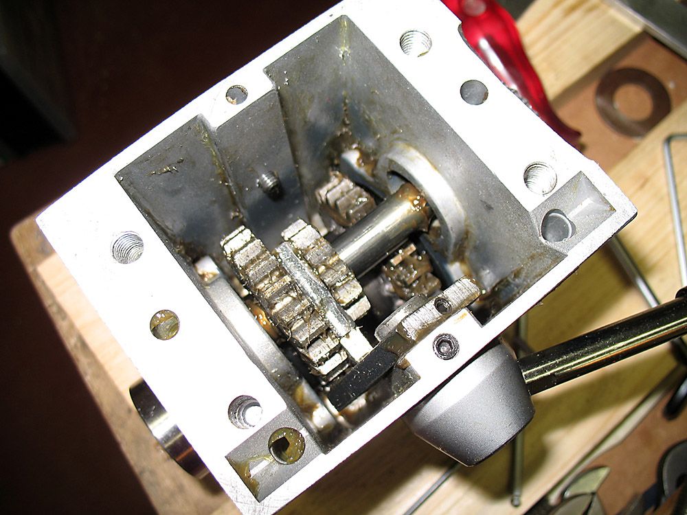
But what to do about lubricating the new metal gears? Easy enough to apply grease while putting it together, but what about later on when that original grease gets flung off the gears to leave them run dry? I didn’t want to jam all of that original grease back into the transmission again. So at this point I made one alteration to the mill transmission housing. I drilled and tapped a hole (6mm threading) into the side of the transmission housing just in line with the intermediate drive shaft. A short bolt with a rubber washer does duty as a plug to seal the opening.

This hole serves as a handy lubrication port through which I can squirt discrete amounts of grease directly onto the intermediate shaft and gears as required. I really wonder why the factory never thought to include lubrication access in the original design.

Now it was finally time to reassemble the mill head and bring everything back to running condition. But again another fly in the ointment…
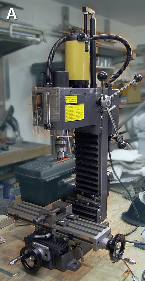
The transmission and main spindle case needs to be bolted to the mill head section that rides in the dovetails on the column. Naturally, the spindle must be aligned axially with the column, but sadly the two units are not keyed to one another and lining them up proved most annoying.
In his article, “Improvements to an X2 Mill”, Neil Wyatt refers to this procedure with the following:
“Before completing the setup, you need to refit the two parts of the mill head to each other. Careful inspection seems to indicate the upper surfaces of the two parts are the reference faces for their alignment.”
Well, that is how it is done for the old Sieg X2.
On the other hand, owners like me of the even older CH-10M will be most disappointed when they realize that there are absolutely no flat, clean reference faces on the two parts of the mill head to facilitate this operation. Obviously there must have been a jig for assembling these parts in the correct relationship to one another in the factory. But for the end user, out in the field, the re-assembly of these parts is a matter of some frustration.
My solution for lining up the two mill head sections was to mount my ER25 collet holder in the spindle. Into the collet holder went a length of hardened 8mm shafting from an old computer printer. The two parts of the milling head were then lightly bolted together, this assembly then being slid onto the column and locked in place
There is absolutely no provision for delicate adjustment of the relationship of the two parts one to the other, so it was then a matter of tap-tap-tapping the head this first this way and than that while holding a machinist’s square from the X-Y table against the length of hardened shafting.
Complicating this procedure is the fact that the bolts which secure the two parts of the mill head to one another are not accessible for tightening while the mill head is mounted on the column. So of course it took repeated iterations of tapping to what seemed to be correct alignment, pulling the mill head up and off to tighten the bolts a bit more and then sliding it back onto the column once more to again repeat the checking and tapping. I achieved what appears to be a reasonable alignment, but, please, don’t anyone ask me to hold a dial test indicator to the end result.
The mill is now completely reassembled and running (and rather nicely, at that). It will serve me for a while longer while I make a decision as to which newer, larger model will replace it
Ignatz.


