Proxxon MF70 went bang

Advert

Proxxon MF70 went bang

Home Forums Help and Assistance! (Offered or Wanted) Proxxon MF70 went bang

Viewing 25 posts - 26 through 50 (of 50 total)
  • Author
    Posts
  • #393916
    Bill Phinn
    Participant
      @billphinn90025
      Posted by John Haine on 31/01/2019 15:03:25:

      Can you smell something from the motor itself?

      Not now, but the acrid smell did linger for about half an hour after the event.

      Advert
      #393920
      Andy Carruthers
      Participant
        @andycarruthers33275

        Can you see the motor windings and commutator or is it a sealed unit?

        Blackened / burnt varnish on the windings is what we hope not to see

        It could be the brushes have worn out, can you pull them out and check their condition – length is key as is the commutator face-end

        #393936
        John Paton 1
        Participant
          @johnpaton1

          Hmmm from that description it could be motor but it could still be one of the capacitors. You really need somebody nearby with a bit of electrical knowledge, a multimeter and a soldering iron. we could read them through the test sequence but thy ned that minimum kit to take the investigation further.

          If no joy on this forum you could try a model railway forum or electronics forum?

          #393937
          Tim Taylor 2
          Participant
            @timtaylor2

            Bill,

            The intermittent sounds you heard prior to failure could still be related to the controller.

            To check the motor, disconnect the leads from the circuit board and check resistance with a multimeter. If it is open or shorted, you have a motor problem….check the brushes as Andy mentioned.

            From the circuit diagram posted this is a 220V motor – you should be fine using your 18V battery…….stick a fuse in series………

            Tim

            #393941
            Bill Phinn
            Participant
              @billphinn90025

              Thanks for the further replies.

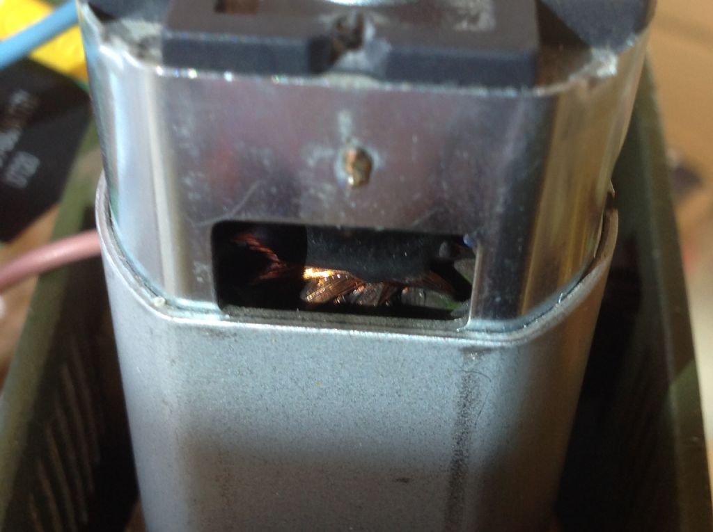
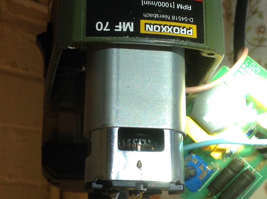
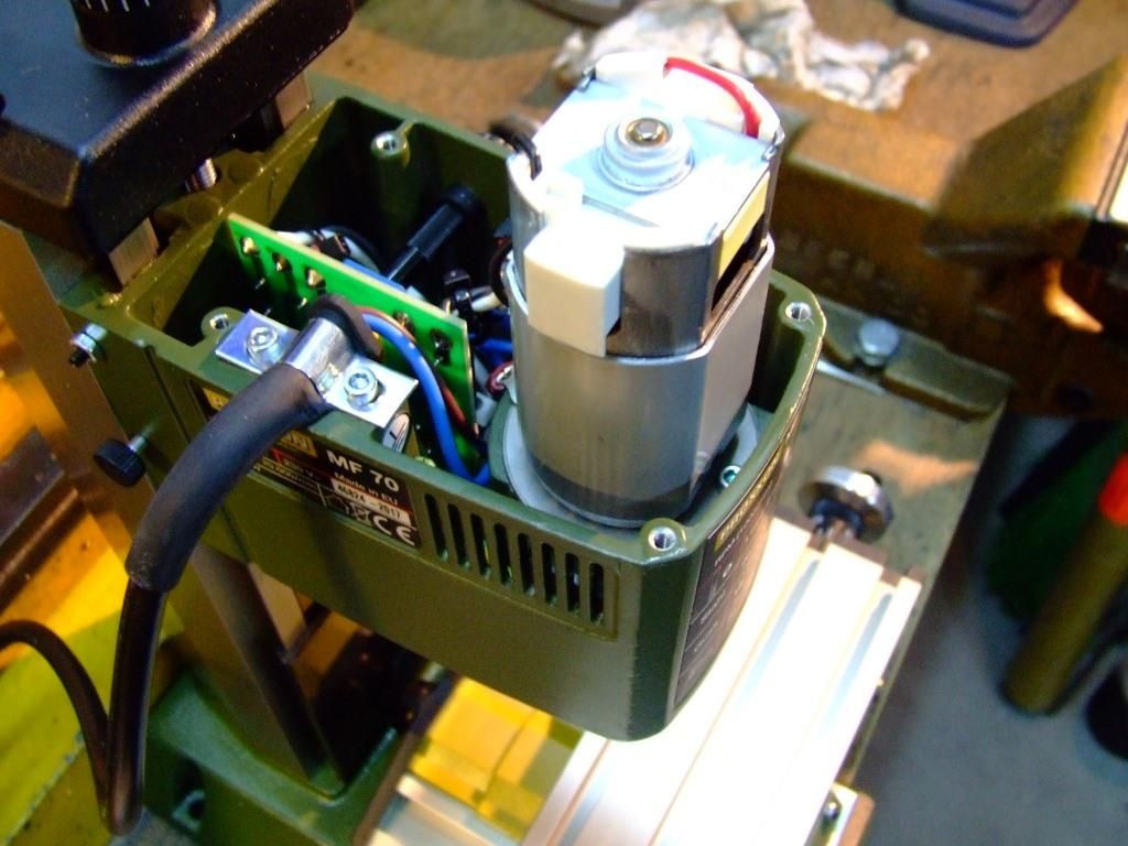
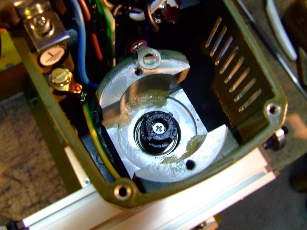
              Andy, the windings are partly viewable. I've taken the best photos I'm capable of. I've also shown the commutator. The brushes are higher up than is really photographable, but they do look to have plenty of meat on them, although it's a little difficult to tell given the fact that most of their meat is hidden in the (spring-loaded?) holders. I've got to say I don't really suspect the brushes given the relatively short run time this machine has experienced since new.

              img_0834.jpg

              img_0826.jpg

              #393942
              Bill Phinn
              Participant
                @billphinn90025

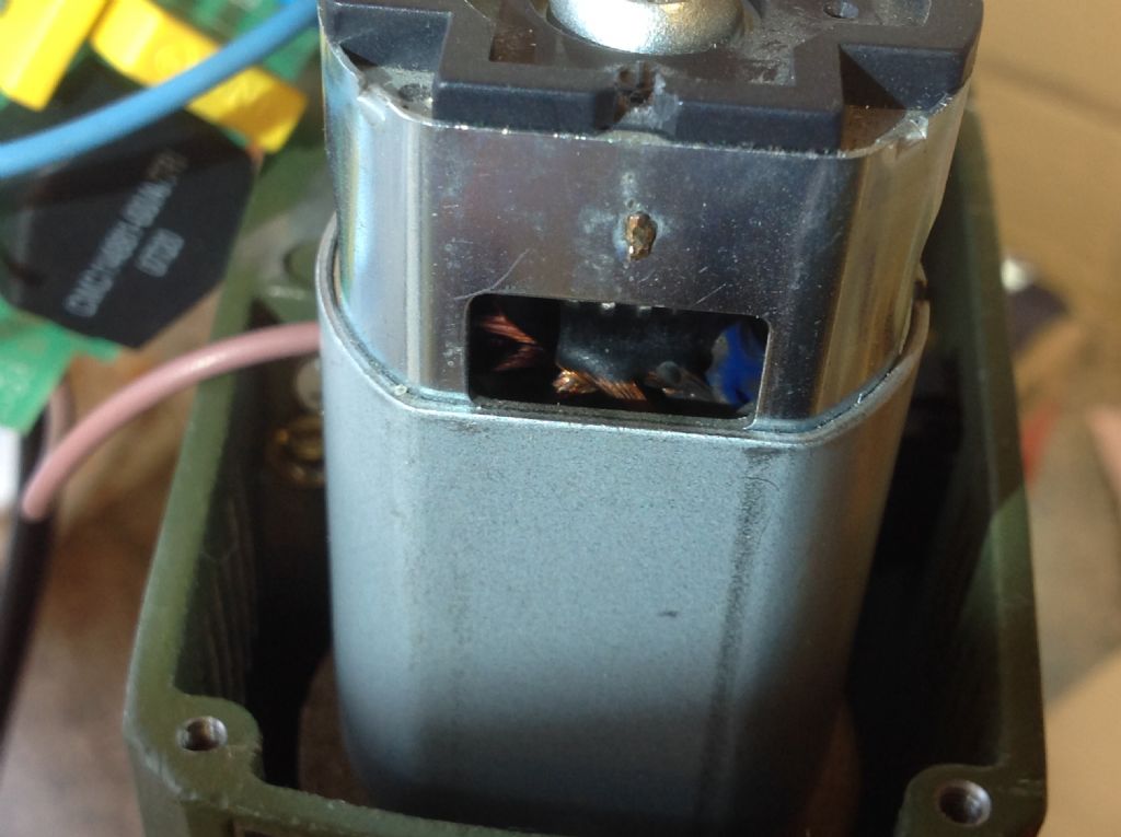
                img_0833.jpgAnother photo of the windings:

                #393953
                Martin W
                Participant
                  @martinw

                  As far as the pictures show the motor doesn't seem to have been over stressed, commutator and windings look to be OK as far as it possible to see and the same applies to the circuit board. I am wondering if it isn't, as earlier suggested, a failure in the mains supply cable near or at the point it enters the head. If this is the case then the machine fuse will have remained intact and the plug top fuse would have taken the brunt and could have blown with an audible pop. This would also fit in with the motor occasionally stuttering prior to the failure as the break in the cable intermittently failed. If the plug fuse has blown then without having the ability to check the cable with a meter it may be worth replacing the supply cable and trying it again to see if there is any response. Another way would be to use a mains indicating screwdriver/tester and after replacing the plug fuse see if there is any indication of the mains being present at the circuit board, no need to say really but just be careful when working on exposed mains.

                  Cheers

                  Martin W

                  PS (edit)

                  Another possibility is that there has been a failure of the mains switch on the machine which could, remote chance, of shorting something to earth or may have just failed internally with a bit of arcing hence the smell and failure to run.

                  Edited By Martin W on 31/01/2019 17:48:17

                  Edited By Martin W on 31/01/2019 18:07:41

                  #393973
                  Bill Phinn
                  Participant
                    @billphinn90025


                    Thanks, Martin.

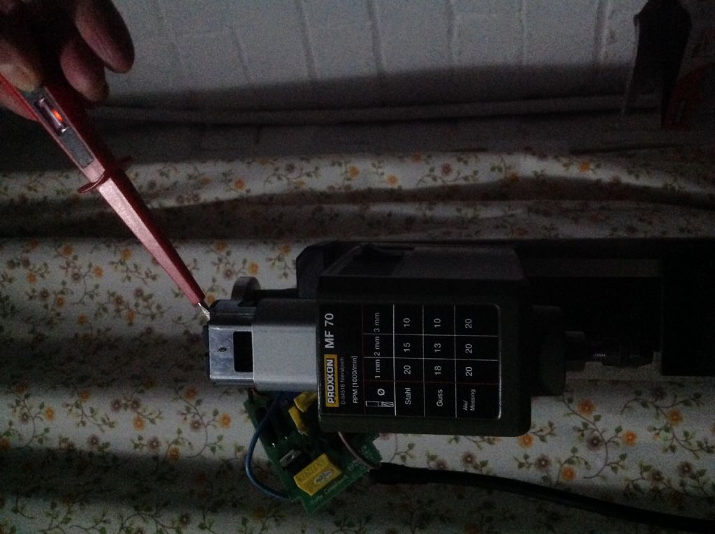
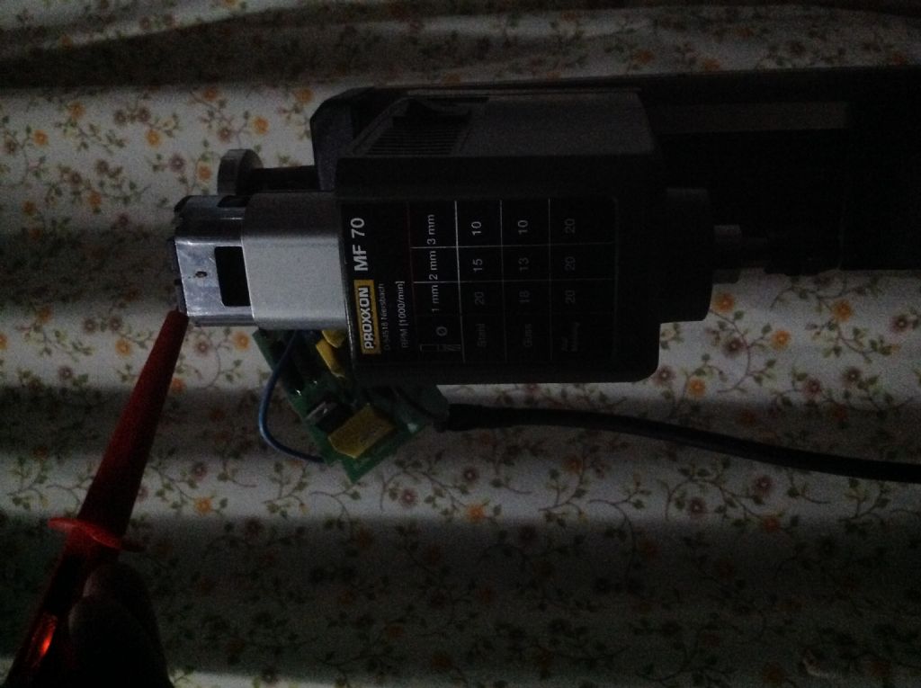
                    I've attached two images showing the result of a neon screwdriver being held to each of the two motor terminals in turn. The fact that it lights up suggests to me a working circuit from the mains via the switch and control board. Does this necessarily mean either the control board or the circuit is healthy? I know it says nothing about the health of the motor.

                    Tim, I forgot to say, I tried the drill battery with an in-line fuse. It didn't power the motor.


                    img_0836.jpg

                    img_0835.jpg

                    Edited By Bill Phinn on 31/01/2019 19:05:27

                    #393984
                    Emgee
                    Participant
                      @emgee

                      Bill, IMO checking with a neon screwdriver is telling you nothing about the state of the controller , they illuminate at the sight of the lowest of voltages and should not be relied upon for such testing.
                      If you haven't got a basic multimeter it would be best and safest to remove the controller and motor and take to your local motor repairers, failing that perhaps a supplier can be found who offers a repair service.

                      Emgee

                      #393985
                      Emgee
                      Participant
                        @emgee

                        double posting removed

                        Edited By Emgee on 31/01/2019 19:22:05

                        #393994
                        Michael Gilligan
                        Participant
                          @michaelgilligan61133
                          Posted by Emgee on 31/01/2019 19:20:43:

                          … they illuminate at the sight of the lowest of voltages …

                          .

                          Typically about 90

                          MichaelG.

                          #393996
                          JRow16
                          Participant
                            @jrow16

                            I've had a Proxxon MF70 for 5 yrs now. It stopped working after about 6 months so I sent it back to the supplier. They replaced the circuit board and motor.

                            Then just after the years warranty had run out it stopped working again. There was a small bang and a slight smell of burning. Not knowing how to test it properly, I just ordered a new motor, I can't remember where I got it from but I think it was from a German supplier. It needed a little soldering but it was quite easy to replace and it's been working fine ever since.

                            I only use it for plastics these days though.

                            #393999
                            Michael Gilligan
                            Participant
                              @michaelgilligan61133
                              Posted by Bill Phinn on 31/01/2019 18:44:48:

                              img_0836.jpg

                              .

                              No guarantees, but …That looks encouragingly like a DC voltage being indicated.

                              So now I'm wondering: Is the motor physically seized rather than electrically faulty.

                              MichaelG.

                              .

                              From Wikipedia:

                              Most small neon (indicator-sized) lamps, such as the common NE-2, have a break-down voltageof around 90 volts. When driven from a DC source, only the negatively charged electrode (cathode) will glow. When driven from an AC source, both electrodes will glow (each during alternate half cycles). These attributes make neon bulbs (with series resistors) a convenient low-cost voltage tester. By examining which electrode is glowing they can reveal whether a given voltage source is AC or DC, and if DC, the polarity of the points being tested.

                              https://en.m.wikipedia.org/wiki/Neon_lamp

                              Edited By Michael Gilligan on 31/01/2019 20:10:02

                              #394002
                              John Rudd
                              Participant
                                @johnrudd16576

                                I did suggest checking with a light bulb…

                                Hope you get it sorted..

                                Edited By John Rudd on 31/01/2019 20:19:08

                                #394003
                                John Paton 1
                                Participant
                                  @johnpaton1

                                  You could try a version of JR's advice and put 12v supply across the motor (positive feed to the red lead). This will not harm the circuit board as the diodes in the circuit should do that. If the motor starts to run you know it is OK and the board is suspect. I am assuming the motor is not connected to the lathe and so is able to spin freely. Have you tried spinning it by hand for any signs of roughness? (it will have friction from the commutator brushes but that should be quite smooth)

                                  The other test that might add a clue would be to remove one lead from the motor and then test the end of that lead with your neon and also the other lead where it connects to the motor. If the circuit is working I would expect both leads to show a voltage (+ or – 100V therefore giving 200v across the motor). You might also find the lamp stops working if the controller is turned down to minimum speed.

                                  If that is what happens it would, to my mind, edge the probability towards motor failure.

                                  #394019
                                  Fowlers Fury
                                  Participant
                                    @fowlersfury

                                    Amidst all the electronic experts here, this will be inviting ridicule but….
                                    Bill, seeing your pics of the exposed motor with carbon brushes brings to mind an experience with my (also German) Wabeco mill. Before coming to a final stop, though without a loud bang, the motor started to "stutter" for a couple of minutes. Dismantling revealed that the German "design" had resulted in carbon particles abraided from the brushes covering the speed controller pcb. A blast from the air compressor to clear them all, then covering the pcb with plastic sheet and full function was restored.

                                    #394062
                                    Martin W
                                    Participant
                                      @martinw

                                      Bill

                                      If you can do it safely then test the point at which the blue wire is connected/soldered to the pcb with the power on. If the neon lights up then you would appear to have a break in the neutral line to the mill. If there's no reaction then the neutral should be OK and we can discount the supply cable for the time provide the plug has been wired correctly.

                                      FF carbon brush dust build can cause problems but most of the dust is deposited in the motor where it can provide a leakage/short to earth and this frequently causes an RCD trip. If you look at the pictures Bill has posted the actual speed controller board looks to be be reasonably clean and free of any significant contamination. That said I feel that any contribution is welcome as it can make people look again at the problem and this sometimes proves to be very useful.

                                      I think that anybody who just dismisses another's comment as stupid or rubbish not only show themselves up but do a disservice to the forum and can make others hesitant to make a contribution.

                                      Cheers

                                      Martin W

                                      #394065
                                      Emgee
                                      Participant
                                        @emgee

                                        I think that anybody who just dismisses another's comment as stupid or rubbish not only show themselves up but do a disservice to the forum and can make others hesitant to make a contribution.

                                        Cheers

                                        Martin W

                                        Martin, is this comment in reply to my contribution ?

                                        Emgee

                                        #394067
                                        Fowlers Fury
                                        Participant
                                          @fowlersfury

                                          Martin et al,
                                          I should have written that the carbon particles had deposited on the underside of the pcb on my mill and were causing the tracking. Bill's pictures only show the component side of his pcb and I agree – that side looks clean.
                                          It took me a while to notice the "light dusting" of particles on my pcb, they weren't that obvious on a cursory look.
                                          There was no ventilation on the motor housing and I assume the motor's rotation had distributed the carbon dust.

                                          (It was a design fault cured by fitting the plastic cover over the base of the pcb and later, by fitting a computer-case fan adjacent to the brushes. That fan acquires a suprising amount of carbon !)

                                          #394068
                                          Martin W
                                          Participant
                                            @martinw

                                            Emgee

                                            Not at all in fact it was FF's comment regarding and I quote, "Amidst all the electronic experts here, this will be inviting ridicule but…."

                                            With regard to your posting I agree that using a neon indicator severely limits any meaningful tests being performed. However if this is all Bill has then use can be made of it to see if the mains supply is reaching the mill and whether physical switches are working. It may also be possible to identify, on the live side of the circuit, where there is a break i.e. Dave suggested that one of the inductors may have failed and it could be possible to identify a fault of this nature using a neon based tester. It's a case of using what is at hand to help eliminate or confirm any problems.

                                            Hope this puts your mind to rest.

                                            Martin W

                                            #394069
                                            Tim Taylor 2
                                            Participant
                                              @timtaylor2

                                              Bill,

                                              IMHO, as an EE with >40 years experience, at this point you need to get some quantitative measurements.

                                              If you don't have a multimeter, see if you can borrow one.

                                              First, power off, disconnect the motor and check it's resistance – according to the posted schematic it should be 90 ohms. If it deviates from that by more than 10-12%, you likely have a motor problem.

                                              Note: The following measurements need to be done with the power on and the motor disconnected.

                                              SAFETY FIRST! The voltages present can kill you, so if you're not comfortable doing this, get some help.

                                              AC voltage at the input to the control board
                                              DC voltage at the control board output (will vary depending on the speed control pot setting.

                                              If there is no DC output, next step is to check the AC voltage at the input of the rectifier bridge – it will also vary depending on the pot setting. This will isolate the problem to either the rectifier section or triac section of the circuit.

                                              Let me know what you find and I will tell you where to look next.

                                              Hope this helps……….

                                              Tim

                                              #394278
                                              Bill Phinn
                                              Participant
                                                @billphinn90025

                                                Many thanks to everyone for your replies.

                                                Michael, the motor appears not to be seized if the free turning (by hand!) of the spindle and commutator et al. is anything to go by.

                                                JRow16, on the plus side your double failure of an MF70 makes me feel less unlucky than I otherwise might have done, but it has virtually sealed my unwillingness ever to put money into a piece of Proxxon machinery again. Was this the place you ordered the motor from: https://www.fluidonline.de/proxxon-28481-19-motor-mit-stuetzring-fuer-ib-e-ibs-e-ersatzteil/a-5776/.?

                                                If so, I'm not sure whether it makes any difference, but the part number is one digit different from mine (which ends -11, not -19). While we're at it, I'd be interested to know how you uncoupled the old motor; I did try removing the two retaining screws at the base of the motor but it seems it can't be lifted away unless the spindle locknut is first removed, and I'm not sure how that's done.

                                                John Paton, I wil try your second suggested test this weekend, thank you. I'll have to desolder the motor terminal wires anyway if I'm to do Tim's suggested resistance testing.

                                                Tim, it turns out my brother has a decent quality multimeter and he used it only yesterday to check the resistance on his newly installed underfloor heating; I could always buy my own rather than wait till I see him next. I will try your suggested tests as soon as I am fixed to do so.

                                                Posted by Martin W on 01/02/2019 00:22:30:

                                                Bill

                                                If you can do it safely then test the point at which the blue wire is connected/soldered to the pcb with the power on. If the neon lights up then you would appear to have a break in the neutral line to the mill. If there's no reaction then the neutral should be OK and we can discount the supply cable for the time provide the plug has been wired correctly.

                                                Martin, I have just done this test, touching the screwdriver tip to the solder at the back of AC wire. The potentiometer was turned all the way up and yes, the neon illuminated. You say this would appear to mean a break in the neutral line. Can you tell me in simple terms how we know it means that, and how I can trace the location and or cause of the break?

                                                Incidentally, can anyone tell me why this message occurs, which appeared multiple times when I attempted to post this latest post, and has occurred frequently in the past: "Your posting is 112556 characters too long, please split it into two or more separate posts".?

                                                #394444
                                                JRow16
                                                Participant
                                                  @jrow16

                                                  Bill

                                                  Yes, I did order it from fluidonline back in 2015. The part no. that I ordered was 27110-113.

                                                  I can't remember how I removed the motor, usually I think that I would have followed online instructions but I can't find any link on my PC.

                                                  #394642
                                                  Roger B
                                                  Participant
                                                    @rogerb61624

                                                    There was apparently a design change in the MF 70 motor so the detail of the part number may be important.

                                                    This company offers a possibility:

                                                    **LINK**

                                                    The parts list is here if you don't already have it:

                                                    **LINK**

                                                    I have removed the motor from my (probably newer) MF 70. There is a screw either side of the motor and then you have to pull the motor out of the coupling. The older version appears to be more like a gear.

                                                    005 drive motor and speed control board.jpg

                                                    006 spindle drive coupling.jpg

                                                    Best regards

                                                    Roger

                                                    #394656
                                                    Bill Phinn
                                                    Participant
                                                      @billphinn90025

                                                      Many thanks, JRow and Roger.

                                                      Roger, I've tried pulling on the motor after removing the screws but there doesn't seem to be a hint of willingness to budge. I suspect I do have the older version. It seems I was wrong about having had the item eight years; I've actually had it over ten.

                                                    Viewing 25 posts - 26 through 50 (of 50 total)
                                                    • Please log in to reply to this topic. Registering is free and easy using the links on the menu at the top of this page.

                                                    Advert

                                                    Latest Replies

                                                    Viewing 25 topics - 1 through 25 (of 25 total)
                                                    Viewing 25 topics - 1 through 25 (of 25 total)

                                                    View full reply list.

                                                    Advert

                                                    Newsletter Sign-up