Myford S7 Cutting Barrel Shaped Cylinders

Advert

Myford S7 Cutting Barrel Shaped Cylinders

Home Forums Workshop Tools and Tooling Myford S7 Cutting Barrel Shaped Cylinders

Viewing 25 posts - 26 through 50 (of 114 total)
  • Author
    Posts
  • #474439
    Michael Gilligan
    Participant
      @michaelgilligan61133
      Posted by Hopper on 24/05/2020 09:41:04:

      I was refering to Jason's suggestion of a three-collar test bar in the previous post.

      .

      So perhaps my comment should have been addressed to Jason

      Advert
      #474442
      JasonB
      Moderator
        @jasonb

        "It’s a worn lathe, giving ‘worn lathe’ performance."

        Agree with that Michael

        Advantage of the bobbin type test is your tool stays nice and sharp doing two ( or 3) 1/4" wide cuts so giving a more consistent reading than turning a whole long length. You can also make it with "rings" loctited to a shaft and keep that for testing setup and simply heat the rings off when too small and fit new, saves wasting lots of bar.

        Even using a between ctrs test piece could be a problem if the tailstock had droop or wear to match that of the bed, one of the downsides of buying old machines I suppose.

        Edited By JasonB on 24/05/2020 10:20:22

        #474448
        blowlamp
        Participant
          @blowlamp

          In practice, it's not that big a job to give the vertical shears a 'lick' with the scraper to remove the worst of the wear.

          You wouldn't get an award for "Engineering Excellence", but you could do it without dismantling the carriage and even use said carriage to check for tight spots as you progress.

          What's to lose? smiley

          Martin.

          #474451
          Hopper
          Participant
            @hopper
            Posted by blowlamp on 24/05/2020 10:32:55:

            In practice, it's not that big a job to give the vertical shears a 'lick' with the scraper to remove the worst of the wear.

            You wouldn't get an award for "Engineering Excellence", but you could do it without dismantling the carriage and even use said carriage to check for tight spots as you progress.

            What's to lose? smiley

            Martin.

            If you have the requisite skills and scrapers and scraped straight edge and square for reference. And not if the carriage is equally as worn as the bed. (Usually the carriage is more worn than bed). For the average home shop worker I think it would better to try the very simple wide guide conversion and if the vertical wear is still a problem, pay for a regrind. It's a Super 7 so worth spending money to refurbish, given the outrageous resale price.

            #474458
            blowlamp
            Participant
              @blowlamp
              Posted by Hopper on 24/05/2020 10:40:16:

              Posted by blowlamp on 24/05/2020 10:32:55:

              In practice, it's not that big a job to give the vertical shears a 'lick' with the scraper to remove the worst of the wear.

              You wouldn't get an award for "Engineering Excellence", but you could do it without dismantling the carriage and even use said carriage to check for tight spots as you progress.

              What's to lose? smiley

              Martin.

              If you have the requisite skills and scrapers and scraped straight edge and square for reference. And not if the carriage is equally as worn as the bed. (Usually the carriage is more worn than bed). For the average home shop worker I think it would better to try the very simple wide guide conversion and if the vertical wear is still a problem, pay for a regrind. It's a Super 7 so worth spending money to refurbish, given the outrageous resale price.

              Yes, I did mention that in my first post. In my previous post I was thinking more of a 'get a bit more accuracy' type of fix without doing a complete refurb.

              I've done similar myself using scraper, files, some ground stock and a little blue and it's surprising how well a simple bodge job can work.

              Martin.

              #474462
              Hopper
              Participant
                @hopper

                Blowlamp, yes such a "simple bodge job" could be better than nothing if wide guide is not an option. Good idea using gauge plate as a reference surface. Ive done similar with large section key steel before too. It's surprisingly flat (by bodge standards laugh ) And you could mike off the relatively unworn front shear.

                But if I had an S7 I would spring for the regrind given the resale value and the quite nice lathe you would have as a result. Depend's on one's budget of course. And nobody's retirement fund is going gangbusters at the moment. (Unless you are Jeff Bezos or one of those guys.)

                Edited By Hopper on 24/05/2020 11:02:48

                #474579
                Mike Donnerstag
                Participant
                  @mikedonnerstag

                  Firstly, I'd like to thank everyone who replied. I expect all of you have a greater engineering knowledge than I. I did a little toolmaking on my violin making course during 2012-2016 and have only been doing more at home since then, firstly in a severely limited way with a Myford cross-slide fitted to my woodworking lathe (!), then with the Myford S7 I bought at the start of last year, and more recently with the purchase of the Sieg SX3 mill.

                  I knew the Myford was an old lathe with an unknown amount of wear, but I thought it was a great price (£1500) for one with a gearbox and power cross feed. It’s from 1982-ish, so the saddle is already ‘wide-guide’. I’ll try to reply to everyone separately below, so please excuse me repeating myself, and apologies for anyone I've missed!

                  Pete Rimmer: The idea of compensating for an out of line headstock makes complete sense to me. If the axis is pointing towards the back right corner of the lathe and the front right foot is raised to compensate, in my mind at least this would explain the barrel shape. Just an idea: would an iron casting such as a lathe bed spring back to its original flatness, or thereabouts, confirming this? If so, I could see what happens when I slacken the two nuts at the right end of the bed.

                  Unfortunately, I don’t have access to a machinist’s level, but if there is anyone on here who could help, in the Lincolnshire area, I would be eternally grateful. Having said that, it seems that not everyone is in agreement that it would help identify the problem.

                  Graham Meek: I’ve been using a freshly sharpened piece of 3/16” HSS held very solidly in a tangential toolholder made by a very capable young chap who is head of the engineering workshops at Newark college. He has given me a great deal of help, that is, until he fell off his push-bike and broke his hip at the start of the year! Anyway, I made sure the depth of cut was the minimum necessary to remove metal from all the way along the shaft, between 1 and 2 thou. The tool cut very sweetly with no chatter on the mild steel bar (not sure whether it was leaded for free-cutting, but it cut well). The cutter was sharpened with no radius, but has retained its edge during the eight or so test cuts, giving consistent results.

                  I’ll try the ‘test bar test’ tomorrow (I’ve been solving lockdown relationship problems today – my own relationship that is – very tiring!!) using the (probably Chinese) 11” (including taper) MT2 test bar from eBay recently. It’ll be interesting to see what this shows. I’ll keep you updated on my findings.

                  My overhaul so far has really only covered the carriage. The bed wiper felt was completely missing when I purchased the lathe, so this was the first job I did last year, as well as removing, thoroughly cleaning and oiling the saddle. The underside of the saddle is quite scored. More recently I replaced one of the apron bearings, which was so bad it leaked oil from the apron sump. Apart from adjusting the bearings and giving the whole machine a good clean and oil, I haven’t touched the headstock.

                  I have completely ignored the tailstock so far in my setting up since replacing the apron, as I considered its alignment to be just another variable to contend with and confuse issues further.. though more on this below.

                  (By the way, I have your handwheel dial fitted that I purchased from Steve Tracey – great design and a fantastic bit of kit!)

                  Martin Kyte: I haven’t noticed any rigidity problems with the ER40 collet chuck, going by the lack of chatter. The cut has been very light; no more than 2thou.

                  Blowlamp: I’m coming to the conclusion that it may well be just bed wear that I’ll have to live with, until I dismantle everything and have the bed reground, which seems to be worth considering. The lathe is from 1982 and therefore already has the ‘wide guide’ saddle, hence my taking the measurements from the full width of the bed.

                  I have absolutely no experience with metal scrapers, even though I do own several blunt ones. Without someone who knows what they were doing, I’d be afraid of doing more damage than good.

                  To be continued…

                  #474580
                  Mike Donnerstag
                  Participant
                    @mikedonnerstag

                    Continued from above…

                    Hopper: Yes, pretty borderline wear it seems. The lathe is a post-1972 wide-guide version. Regrinding may well be the answer if I need greater accuracy.

                    Not done it yet: Wouldn’t bringing the tailstock into play just add to the number of variables contributing to the problem? Or, would it definitively isolate the issue to the bed, thereby proving that the headstock alignment is not to blame?

                    JasonB: I could try taking a heavier cut, though I’m expecting chatter at the outboard end to confuse the measurements.

                    Michael Gilligan: You may well be right about the lathe bed just being worn, with a regrind the only way to increase accuracy.

                    To summarise…

                    I will try the MT2 test bar suggested by Graham Meek and turning between centres suggested by Not done it yet. If that doesn’t help identify the issue, I’ll have to decide whether to live with the inaccuracy, or to stump up for a regrind. Actually, the dismantling, transport and subsequent reassembly and alignment scare me more than the cost, which is within my budget.

                    Just an idea: If the problem is due to bed wear, would it be worth checking and adjusting the flatness of the saddle gib strip to ensure it is bearing on as much of the front shear of the bed as possible? That way, perhaps it might skate over the bumps instead of diving into the hollows?

                    #474631
                    Pete Rimmer
                    Participant
                      @peterimmer30576
                      Posted by Hopper on 24/05/2020 09:46:57:

                      Posted by Pete Rimmer on 24/05/2020 09:42:44:

                      The saddle and tailstock run on different parts of the flat way, the tailstock will never wear the chuck end and the saddle won't appreciably wear the tailstock end, so you can actually put a level on either end quite confidently as it will sit on the un-worn parts both ends unless the wear is particularly heavy or the top surface damaged with dings and burrs.

                      This doesn't stop the saddle rotating on the worn bits but it does give you a baseline to start your measurements. from.

                      But the saddle runs on the full width of the top horizontal surface of both ways. So saddle wear is full width. Problem is the front way way takes most of the load and wears more than the rear way. Unless the Super 7 carriage is different from the ML7? (It doesn't appear to be but I dont have one to hand to check.)

                      I suppose you could measure the actual wear on the bed and shim the level accordingly??? Or build a "sled" that referenced off the relatively unworn underside of the shears where the lift plates run and sit your level on that??? Tricky though.

                      Edited By Hopper on 24/05/2020 09:57:47

                      Ah right, I didn't realise that. I have scraped a 7 bed from end to end (hand-scraped 7 thou of wear out of it) but never used one.

                      Your next best option would be to pop the headstock off and put the level on there.

                      #474731
                      Graham Meek
                      Participant
                        @grahammeek88282
                        Posted by Mike Donnerstag on 24/05/2020 19:27:10:


                        Graham Meek:

                        (By the way, I have your handwheel dial fitted that I purchased from Steve Tracey-great design and a fantastic bit of kit)

                        Hi Mike,

                        Thank you for the kind comments about the Handwheel Dial. Steve makes a better job of them than I did, he has the kit to do it with.

                        Generally

                        As regards using an Engineers Level with a worn Flat Bedway. It is known that the wear on this particular Bedway is 0.0025". A feeler blade, which is a standard in my Moore & Wright set of gauges, can be interposed between the Bedway and the Level which will restore the Status Quo. No need for any further dismantling, or ruling out the use of a Level to check a worn bedway.

                        Regards

                        Gray,


                        Edited By Graham Meek on 25/05/2020 10:19:06

                        #475863
                        Mike Donnerstag
                        Participant
                          @mikedonnerstag

                          Unfortunately I don't have any engineering friends from whom I could borrow a level. Do you have any recommendations for one that I could purchase? I noticed that RDG have unnamed (Chinese) levels from about £52, or Moore and Wright for £144. Nice tools, thought I'd probably only use them once!

                          Or…

                          Is there anyone anywhere near Lincoln who could perhaps lend me a level?

                          Mike

                          #475893
                          Graham Meek
                          Participant
                            @grahammeek88282

                            Hi Mike,

                            While a level is the quickest and easiest way to check for twist, it is not the only way.

                            In my first post I outlined the use of a length of Silver Steel or Precision Ground Mild Steel. I used this method to set up my Maximat lathe the last time I moved the shop around.

                            I bought an 8" Engineers level second hand form an advertiser on here. It is a Rabone and Chesterman circa 1970's. I don't know what accuracy it is, but it is fussy. When I checked my lathe with this level I found it was not that far out, given I had used the Ground bar test.

                            Unfortunately I am the other side of the country in the Forest of Dean, or you could gladly borrow my level.

                            Regards

                            Gray,

                            #475897
                            Mike Donnerstag
                            Participant
                              @mikedonnerstag

                              Hi Gray,

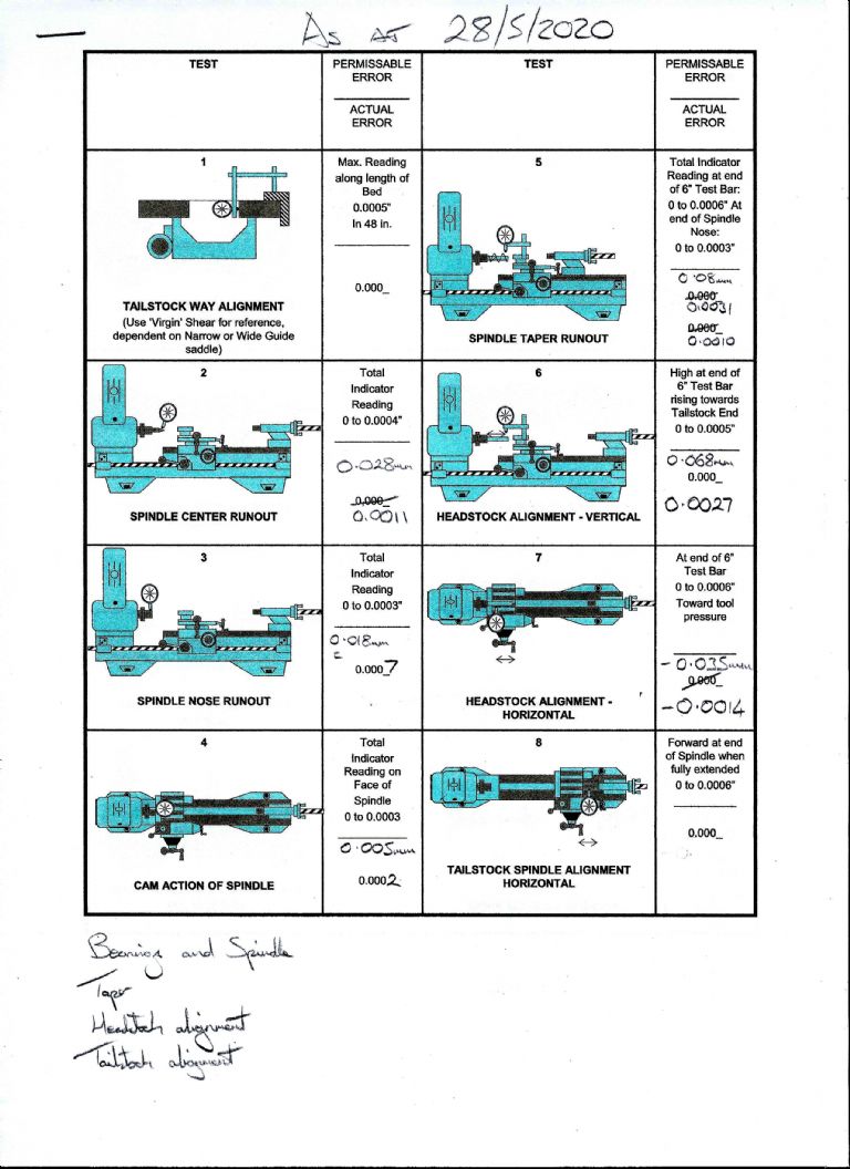
                              I printed a Myford alignment test sheet, and my tests have shown the spindle to be quite outside of tolerances, as follows:

                              my myford alignment tests.jpg

                              As such, I don't think I can trust the accuracy of my spindle taper.

                              Do you have think the bearings may be worn, or need adjusting?

                              Mike

                              #475915
                              blowlamp
                              Participant
                                @blowlamp

                                I don't think there's is much point in using a precision level to check your lathe if it's generating a barrel shaped part.

                                A level would be a good tool to use to correct a taper though.

                                Martin.

                                #475921
                                Graham Meek
                                Participant
                                  @grahammeek88282

                                  Hi Mike,

                                  I am a little confused by the XXX "mm" readings which in some instances are larger by a factor of 10, from what I would want to see, taking the 0.068 mm on the Headstock Alignment-Vertical as an example.

                                  Did you check the Test Mandrel for concentricity before you used it? It might be new but it would not be the first time I have experienced one that was wrong.

                                  Placed on dead centres in the lathe and spun by hand under a clock will prove this to be a good one, or otherwise. Clock at the small end of the taper, the large end, the plain diameter next to the lager end of the taper and at the tailstock end.

                                  There should be Zero error at any location, Plus the test diameter should be exactly parallel. If it is then I think you need to inspect the mandrel taper socket for cleanness and for any damage. As the spindle is hard there should be no damage, but you never know.

                                  I know of one individual who decided to try and drill out his spindle to take a larger bar. I had to internally grind the damage out so that the Morse taper would seat properly.

                                  During these tests above, have you tried clocking the mandrel with the belts under tension. Or have your checks been done in the free state? Too much tension will accelerate wear and if the spindle front bearing is out of adjustment then the belt tension will influence any readings.

                                  A clock on the mandrel chuck register will show if the belts are lifting the spindle as the belt tension is applied.

                                  Adjusting the bearings is not a hard thing to do, but I would like to see what the answers are to the Test Mandrel concentricity test as well as the mandrel taper socket, belt tension etc, before I say any more.

                                  Regards

                                  Gray,

                                  #475926
                                  Martin Kyte
                                  Participant
                                    @martinkyte99762
                                    Posted by blowlamp on 29/05/2020 17:12:37:

                                    I don't think there's is much point in using a precision level to check your lathe if it's generating a barrel shaped part.

                                    A level would be a good tool to use to correct a taper though.

                                    Martin.

                                    Well if it's a combination of spindle bearings and bedway twist the level will eliminate one of these.

                                    I don't think you have done a cut between centres on a test piece. Irrespective of bed twist or tailstock misalignment you should end up with either a tapered test peice or (unlikely) a parallel piece. Either way the testpiece should be 'straight sided) unless you have significant bed wear.

                                    I should like to see you set the bearings up properly first.

                                    Do it like this

                                    1. Power Down

                                    2. Remove all belt tension.

                                    3. Remove Chuck

                                    4. Rotate RH collar one complete turn. (top towards you).

                                    5. Rotate LH collar one complete turn. (top towards you).

                                    Spindle should be completely free of front bush.

                                    6.Loosen allen screw on collar at end of spindle.

                                    7. Using the Allen key tighten collar as tight at it will go by hand.

                                    Inner tapered roller races are now locked together with correct pre-load.

                                    8. Back off LH collar one complete turn + a bit (top away from you)

                                    9. Rocking the spindle by holding the spindle nose tighten the RH collar by hand (top away from you).

                                    10. When you feel resistance to movement stop.

                                    11. Collar should be just tight enough that spindle can just be moved by hand holding the nose.

                                    12. Do up the LH collar by hand (top towards you).

                                    You should still feel resistance when turning the spindle by the nose.

                                    13. With the crescent wrench on the LH collar tap the end smartly with a 12oz hammer.

                                    The spindle should move forwards by a couple of tenths and be completely free running.

                                    14. With the lathe running slowly (lowest direct speed) put the oil gun in the front oil cup and pump until oil issues from the front bearing.

                                    This is how Myfords used to set the lathe up.

                                    regards Martin

                                    #475932
                                    JasonB
                                    Moderator
                                      @jasonb
                                      Posted by Graham Meek on 29/05/2020 17:30:31:

                                      Hi Mike,

                                      I am a little confused by the XXX "mm" readings which in some instances are larger by a factor of 10, from what I would want to see, taking the 0.068 mm on the Headstock Alignment-Vertical as an example.

                                      If as the opening post suggests then it is like ft that the carrage and dti are going down as they are moved away from the headstock due to the 5thou wear in the bed, any of these readings that involve moving the carrage along the bed surely can't read zero.

                                      #475944
                                      Graham Meek
                                      Participant
                                        @grahammeek88282

                                        Posted by JasonB on 29/05/2020 18:15:59:

                                        Posted by Graham Meek on 29/05/2020 17:30:31:

                                        Hi Mike,

                                        I am a little confused by the XXX "mm" readings which in some instances are larger by a factor of 10, from what I would want to see, taking the 0.068 mm on the Headstock Alignment-Vertical as an example.

                                        If as the opening post suggests then it is like ft ?? that the carrage and dti are going down as they are moved away from the headstock due to the 5thou wear in the bed, any of these readings that involve moving the carrage along the bed surely can't read zero.

                                        Hi Jason,

                                        Now I am even more confused, where do "ft" come from.

                                        The point I was asking was where does the "0,068 mm" come from when there is another entry written below on the Vertical Alignment Test which is more in keeping with the required dimension which Myford stipulate.

                                        As regards the "5 thou", I take this to be wear across the bedways and as such will have very little effect on the vertical alignment. Yes there is a measured 0.0025" wear on the bed surface but as this wear only affects the tool height it will not give the effect to the barrel shape that has been found. It might have some effect on the Vertical Alignment if the saddle was under a loading similar to that imposed by a turning tool. In the free state I think the error will not be worth worrying about.

                                        The wear to the vertical face will not extend completely down the bedway, otherwise the lathe would be turning parallel. Thus by using the setting bar technique and running a clock along the side there should be an error which replicates the wear. However there should come a point along the setting bar when the clock reads a fairly constant reading.

                                        Further if a clock is mounted such that the carriage is only working on the less worn portion of the bedway then, the clock should read pretty well zero along its length, provided there is no twist.

                                        My concern at the moment is that there is a twist in the bed, coupled with a semi floating spindle, combined with too long a test piece. Unless the problem is approached in a logical manner then Mike might as well role a dice and pick just any of the replies.

                                        Regards

                                        Gray,

                                        #475968
                                        blowlamp
                                        Participant
                                          @blowlamp

                                          I'm wondering how worn or loose spindle bearings could move to allow both the near & the far end of a test-piece to be cut narrower than the middle portion. indecision

                                          Martin.

                                          #475986
                                          Hopper
                                          Participant
                                            @hopper
                                            Posted by Mike Donnerstag on 29/05/2020 15:51:56:

                                            As such, I don't think I can trust the accuracy of my spindle taper.

                                            Do you have think the bearings may be worn, or need adjusting?

                                            Mike

                                            Yes most definitely. You must. Given the wear on the bed, the bearings are probably similarly sloppy. The bearings should be adjusted as posted by Martin Kyte above before any attempt is made at bed alignment. Otherwise you are trying to align to a moving object. Impossible.

                                            All readings and test results so far are invalid if the headstock bearings have excess play in them. When you said in your OP that you were overhauling your lathe and were now doing the bed alignment I assumed you meant you had already set the headstock bearings to tolerance, as this is the normal sequence of events in lathe overhaul.

                                            There have been whole threads on this forum on adjusting these rather unusual Super 7 bearings so have a bit of a read before you proceed.

                                            Before you adjust, measure your current spindle movement by holding a 12" long piece of 1" bar in the chuck and yank the end of it up and down, and side to side. Have your dial indicator measuring movement of the spindle (not the chuck) right behind the chuck. Record the amount of movement horizontally and vertically. (And let us know what you find.)

                                            Give it a try. You might luck out and be pleasantly surprised.


                                            Edited By Hopper on 30/05/2020 06:05:42

                                            #475991
                                            JasonB
                                            Moderator
                                              @jasonb

                                              Grey Don't know what I was typing there

                                              The two readings on all tests are simply Metric with Imperial below 0.068mm and 0.0027", ones with more are as readings are taken at two places along the bar.

                                              As the DTI is mounted on the carriage or may be held in the toolpost and the wear is likely to be in the 6" nearest the chuck I can't see how it can be moved in a perfectly parallel plane to whats in the spindle, even if wear is side ways unless an elephants foot is being used the dti may not stay on the crest of the test bar

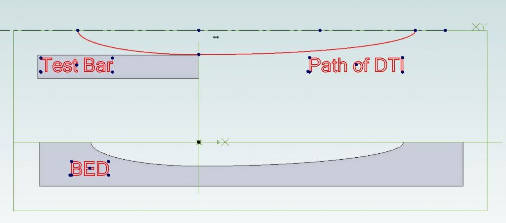
                                              Sketch below shows an exagerated bed with wear and the test bar. As the dti is moved along the bar by the carriage it will dip down as the carriage follows the worn bed and give a +ve reading as the resulting 0.068mm shows. which at 0.0027" is very close to the quoted 0.0025" bed wear, if I were to revolve that red line about the lathe axis you would actually get a barrel shape

                                              dti path.jpg

                                              Edited By JasonB on 30/05/2020 07:33:04

                                              #476015
                                              Graham Meek
                                              Participant
                                                @grahammeek88282

                                                Hi Jason,

                                                Thanks for explaining the dimensions, I would have liked to have heard from the OP.

                                                I was aware the DTI will not stay on the crest of the bar, due to the wear across the bed ways. The amount of "drop off" on the Clock will depend on two things. The diameter of the test bar and the distance moved off centre, let us assume it to be the full 0.005". Simple Pythagoras shows that for a 5/8" test bar the clock will drop 0.00004", too small for me to worry about and a mere fraction of the error found. (It would be less again with a larger diameter test bar.)

                                                What we are not told, and which would be extremely helpful is how this wear progresses down the bedways. The 0.005" could be over just the last 2" of the bed nearest the headstock. It could however be over 10", we are not told this.

                                                This is why the bar test method mentioned initially would show up this wear. Plus as I said earlier, If the the clock is so arranged that the carriage is operating on a less worn part of the bedways then the OP would be avoiding the severity of the wear and proving that there is, or is not, any twist present.

                                                This is also why I initially mentioned the use of the Engineers Level as my first choice. As this method does not involve any machine movements and wear can be very simply compensated for.

                                                Once twist is ruled out then we can move on to the other checks. An un-twisted bed should give 0.010" taper during the turning test, if the 0.005" wear is progressive down the bed. If it is isolated as I suspect, then there might be a very different answer.

                                                Regards

                                                Gray,

                                                Generally,

                                                Like Martin I think the spindle needs looking at, but lets sort one thing out at a time. Otherwise should the lathe miraculously start turning parallel after altering several things we will be none the wiser as to which was the culprit.

                                                When Myford's started building this lathe it was with a flat bed plane. From this everything else is added. It was not assembled and then checked by turning a test piece. Tweaking this and that, to get it to turn parallel and round. The Test Sheets show they went about in a systematic way. This is the fundamental way all machine tools are built.

                                                Regards

                                                Gray,

                                                #476018
                                                Hopper
                                                Participant
                                                  @hopper
                                                  Posted by blowlamp on 29/05/2020 22:26:47:

                                                  I'm wondering how worn or loose spindle bearings could move to allow both the near & the far end of a test-piece to be cut narrower than the middle portion. indecision


                                                  Martin.

                                                  My Myford had almost 15 thou of spindle movement when I got it. The previous owner had been using it like that. Any kind of weirdness can happen as the belt pulls the spindle one way, cutting forces another, the job climbs up over the tool, the job gets pulled into the tool, etc etc. Then add in bed wear moving the tool in another weird direction, both vertically and horizontally, plus wear on the carriage allowing carriage to pivot. Leadscrew alignment and halfnut adjustment can then get involved. And we havent even mentioned gib adjustment. It gets complicated, and weird. Anything can happen.

                                                  You can't align a bed to a spindle that is flopping about all over the place like mine was. It's something that needs to be checked.

                                                  Edited By Hopper on 30/05/2020 09:48:29

                                                  Edited By Hopper on 30/05/2020 09:49:28

                                                  #476023
                                                  Mike Donnerstag
                                                  Participant
                                                    @mikedonnerstag

                                                    Many thanks for all your posts and sorry for the confusion with the readings – I only have metric indicators, hence the conversion.

                                                    Gray: the test bar has been ground to 0.671", though I will double check its accuracy later

                                                    I set up the headstock bearings to the best of my ability a few months ago, having made a peg spanner as a little lathe project. However, as I'm no expert and I'm learning as I go (and doubt many things I do!), I'll do the bearing setup again, following the instructions to the letter and take further measurements after.

                                                    Mike

                                                    #476032
                                                    Hopper
                                                    Participant
                                                      @hopper

                                                      Take some spindle movement measurements before you adjust so you know if they have influenced the tests done so far.

                                                    Viewing 25 posts - 26 through 50 (of 114 total)
                                                    • Please log in to reply to this topic. Registering is free and easy using the links on the menu at the top of this page.

                                                    Advert

                                                    Latest Replies

                                                    Viewing 25 topics - 1 through 25 (of 25 total)
                                                    Viewing 25 topics - 1 through 25 (of 25 total)

                                                    View full reply list.

                                                    Advert

                                                    Newsletter Sign-up