ML10 – ready for the boneyard?

Advert

ML10 – ready for the boneyard?

Home Forums Workshop Tools and Tooling ML10 – ready for the boneyard?

Viewing 25 posts - 76 through 100 (of 105 total)
  • Author
    Posts
  • #366241
    Neil Wyatt
    Moderator
      @neilwyatt

      May I suggest you get a piece of accurately ground silver steel bar, chuck it, and measure its diameter at 1.5cm intervals to 0.0001".

      You will get a series of varying readings, unless something odd is going on.

      As the bar shoudl be of consistent diameter along the full length this should give you a clearer idea of how accurate you measurements are. For example, if you are consistent down to a thou or half a thou.

      Be brutally honest and don't try to get the same reading each time. A hand-held micrometer is NOT actually the easiest of ways to measure accurately, much easier to put the mike in a stand and bring the bar to it, for example.

      Only once you are confident of how small a deviation you can accurately measure can you really make a judgement on your lathe.

      Once close to alignment, there's a simple test – get a ball race with a bore of, say, 0.500", or anything with a decent clean bore to it. See if you can turn a bar to a shake-free sliding fit in the bore along its length. If you can, then the lathe is a good 'un and well set up.

      Advert
      #366246
      Ignatz
      Participant
        @ignatz

        Neil, the resolution of the micrometer I have at hand is 0.01mm (discounting an eyeballed .005 in-between marks) which only equates to 0.00039 inch, this being much coarser than your suggested level of accuracy.

        Nevertheless, I shall do as you suggest with that length of 14mm silver steel rod I used for the 'Rollie's Dad's' test.

        Edited By Ignatz on 08/08/2018 10:51:11

        #366253
        blowlamp
        Participant
          @blowlamp

          Get yourself a scraper and have a go at the bed dovetails.

          Martin.

          #366255
          Mick B1
          Participant
            @mickb1
            Posted by Michael Gilligan on 08/08/2018 10:04:21:

            Mick,

            I think we are at cross-purposes … sorry if I wasn't sufficiently explicit.

            When I wrote 'If the existing dovetail edges were machined off' I meant exactly that … i.e. the top of of the Myford casting would now have vertical edges and be of reduced width … allowing the new plate to have the same profile as the original.

            MichaelG.

            That is what I thought you meant. So your new plate has dovetailed external sides to match the Myford original, vertical internal faces to fit the modified casting, and enough horizontal thickness on top to maintain its profile.

            But presumably you're going to fit the headstock, tailstock and saddle to the new plate in the same or similar manner to the way they were fitted to the original bed, so I can't see how you'd change the centre height or anything else in the basic geometry. And unless you took the bed top surface down far enough to maintain the same height as the original, wouldn't you run into the leadscrew bracket issues in earlier postings?

            Edited By Mick B1 on 08/08/2018 11:03:49

            #366257
            Hopper
            Participant
              @hopper

              WTH? Scrape the bed, or regrind the bed, or remachine and fit a plate because the initial turning test is about half a thou more taper than what would be ideal, before the bed has been properly "levelled" by shimming under the feet as specified by Myford in their set-up procedure? (On the page following the one Michael kindly posted above. Sorry I don't have the tech to copy and post the needed page but I have posted a link to it above.)

              Sledghammers and mosquitoes come to mind.


              Edited By Hopper on 08/08/2018 11:14:56

              #366258
              Michael Gilligan
              Participant
                @michaelgilligan61133
                Posted by Mick B1 on 08/08/2018 11:02:52:

                But presumably you're going to fit the headstock, tailstock and saddle to the new plate in the same or similar manner to the way they were fitted to the original bed, so I can't see how you'd change the centre height or anything else in the basic geometry. And unless you took the bed top surface down far enough to maintain the same height as the original, wouldn't you run into the leadscrew bracket issues in earlier postings?

                .

                Further apologies, Mick … I was about to edit my last post to include reference to the leadscrew, when the roofer arrived at the house to discuss some work.

                As for the centre height : Yes another example of bad wording on my part blush … The centre height above the bench is increased, but the working centre height within the machine is not.

                It's all totally academic in the real world of Ignatz, so let's not labour it any further.

                MichaelG.

                #366264
                Hopper
                Participant
                  @hopper

                  Got it. Here's what you need to do, in addition to taking about .001" of movement out of the headstock spindle by simple adjustment.

                  img_20180808_0004.jpg

                  #366266
                  Michael Gilligan
                  Participant
                    @michaelgilligan61133
                    Posted by Hopper on 08/08/2018 11:10:41:

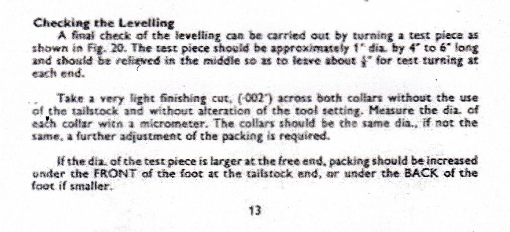
                    … before the bed has been properly "levelled" by shimming under the feet as specified by Myford in their set-up procedure? (On the page following the one Michael kindly posted above. Sorry I don't have the tech to copy and post the needed page but I have posted a link to it above.)

                    .

                    < pedantry alert >

                    The text that I posted is from the ML10 manual, but your link is to the ML7 manual.

                    There is, I believe, a significant difference in the torsional stiffness of the two beds; and the ML10 is not so amenable to adjustment … The ML10 instructions only reference 'without distortion' [suggesting that the ML10, as shipped, was expected to be 'level' in the free-free condition].

                    MichaelG.

                    #366268
                    Hopper
                    Participant
                      @hopper

                      Maybe so. Maybe not. Nobody knows until they try. We are, after all, talking about a very minor taper on a test piece here. My point is, basic engineering trouble-shooting, eliminate the simple stuff first before even considering a $1,000 major engineering project that is way beyond the scope of a beginner who has not yet learned the basics of using a lathe.

                      #366270
                      Neil Wyatt
                      Moderator
                        @neilwyatt
                        Posted by Ignatz on 08/08/2018 10:50:24:

                        Neil, the resolution of the micrometer I have at hand is 0.01mm (discounting an eyeballed .005 in-between marks) which only equates to 0.00039 inch, this being much coarser than your suggested level of accuracy.

                        Nevertheless, I shall do as you suggest with that length of 14mm silver steel rod I used for the 'Rollie's Dad's' test.

                        Exactly .. but you claimed readings to 0.001mm with it!

                        In a-level chemistry I was expected to subdivide a 0.1ml reading to 0.01ml by eye with reasonable accuracy, but I wouldn't have staked my life on the results!

                        Neil

                        #366272
                        Michael Gilligan
                        Participant
                          @michaelgilligan61133
                          Posted by Hopper on 08/08/2018 11:56:47:

                          Maybe so. Maybe not. Nobody knows until they try. …

                          yes

                          #366274
                          Ignatz
                          Participant
                            @ignatz

                            Neil, you are right and the point is well taken. I was only trying to do the best with what I had at hand. And Hopper was quite correct in simply rounding off my measurements. wink

                            #366308
                            Ignatz
                            Participant
                              @ignatz

                              Neil, I did as you suggested, chucked that bar of 14mm silver steel in the lathe and measured it up and down its length, every 1.5 cm.

                              My measurements did NOT vary, the micrometer reading out 13.985 mm at every position. Note: I'm adding on that last '5' because the reading was always between 13.98 and 13.99 on the dial.

                              Then went digging around in a forgotten tool chest under the bench and found an old Lufkin micrometer (model 1641V) that is calibrated in ten thousandths (had been the property of a friend's dad who was a machinist in Milwaukee). The Lufkin gave me a reading from that silver steel bar of 0.5505 inches ( = 13.9827 mm )

                              The readings from the two micrometers are very close to one another… and as far as I'm concerned, the micrometers agree.

                              I then re-measured the free machining steel test bar I had turned. The Lufkin micrometer gave me almost exactly the same readings as I had obtained earlier (but in inch measure), showing a total deviation along the test turning – low to high – of 0.0022 inches

                              So for whatever it is worth, my measurements seem to be valid… disappointing, but valid. sad

                              #366313
                              Ian Hewson
                              Participant
                                @ianhewson99641

                                Sounds as though you have talked yourself into wanting a new lathe, so why not do it and save yourself some time?

                                #366328
                                SillyOldDuffer
                                Moderator
                                  @sillyoldduffer

                                  From the numbers and description, the bed appears to be worn slightly at the chuck end. The amount of error wouldn't worry me much, but its seriousness depends on what the lathe is used for.

                                  Quite a few lathe errors can be compensated for by the operator. Apart from being on the small size, I can't think of anything I do that couldn't be done on this slightly worn ML10 unless something else is also wrong. Admittedly much of what I do doesn't require everything to within tight tolerances.

                                  Ignatz – what are you intending to do with your lathe that needs it to be spot on? Have you tried to make a real part and failed? The symptoms might suggest a work-around.

                                  Dave

                                  #366332
                                  Ignatz
                                  Participant
                                    @ignatz

                                    I was hoping to move a bit beyond the simple down-and-dirty garage maintenance stuff… perhaps into small engines if the spirit moves me.

                                    This whole thread started because my attempts at turning a shaft between centers rendered such disappointing results. Some of the issues that dogged me have been partially resolved thanks to all the helpful comments. Others need still be addressed.

                                    I might have made more progress with my tests and adjustments if it hadn't been for the rather nasty heat wave we have (all) been suffering from.

                                    Anyway, as I stated in a previous post in this thread, I intend to continue to use the lathe as it stands until I can either arrange for a regrind or purchase a (larger) lathe in better condition.

                                    #366393
                                    Hopper
                                    Participant
                                      @hopper

                                      So far, the theory of a worn bed is purely that, a theory. Based on pure assumption, which although a good guide for the direction to look in, is not in itself a reliable guide to what actually is.

                                      Bed wear is easily measured in at least two ways.

                                      1. Set the carriage at the unworn tailstock of the bed and tighten up the gib adjusting screws until the carriage is slightly tight to move up and down the bed by hand. Then move the carriage down to the suspected worn spot near the headstock end. See if the carriage becomes easier to move and if it has noticeable side to side shake or movement possible. Try inserting a feeler gauge between the carriage and the angled surface of the dovetail. With a feeler gauge you should be able to measure how much wear is on the bed. Most of the wear is usually on the rearward-facing surface as the tool is pushed toward the operator during cutting use.

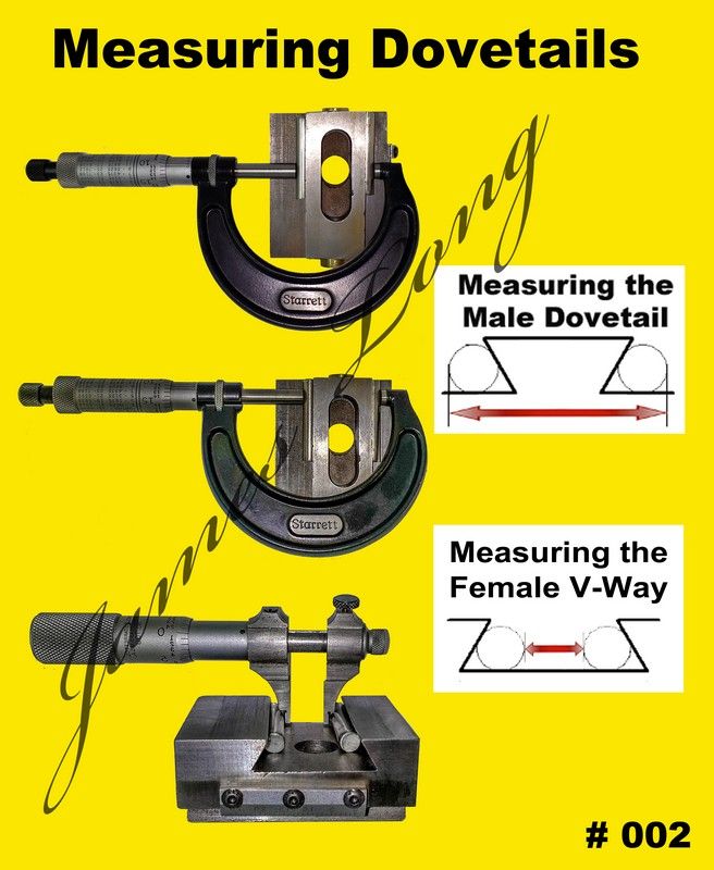
                                      The other way is to measure across two small cylinders, say 25mm long each, places on the dovetails as in the below scenario. Again, compare between the unworn and worn sections of the bed. Diameter of the cylinders must be such that contact with the dovetail surface is somewhere around the middle as in the drawings.

                                      dovetail maeasureing.jpg


                                      However, even if there is bed wear, a certain amount of it can be compensated for on most lathes by shimming the lathe mounting feet or even adjusting headstock alignment.

                                      IN their old brochure about their reconditioning service for the ML7, Myford says more than .003" of wear on the bed in the horizontal direction is time for a regrind. The implication being that up to .003" could be compensated for by  twisting the bed via shimming the feet. (Note that they allow up to


                                      Edited By Hopper on 09/08/2018 01:09:47

                                      Edited By Hopper on 09/08/2018 01:12:25

                                      Edited By Hopper on 09/08/2018 01:15:02

                                      #366637
                                      Ignatz
                                      Participant
                                        @ignatz

                                        Hopper,

                                        I have run the first test you suggested.

                                        I ran the carriage down to the tailstock end, snugged up the gib screws and then brought it back towards the headstock. The movement of the carriage became progressively easier (read looser) towards the middle of the bed way until, very close to the headstock, it became even tighter than at the tailstock end, very difficult to move.

                                        Testing with a bit of shim stock between gib and dovetail proved inconclusive due to limitations, both in my ability as well as the variety shim material thicknesses available to me.

                                        The second test you suggest – measuring across bar material in the dovetail groove will not serve me well here.

                                        The design of the bed of the ML 7, having flat ways with squared off sides means that the wear of the bed on the top is not linked to wear of the sides and/or gib.

                                        On the other hand, on the ML 10 the dovetail design of the bed way means that wear either in the dovetail against which the carriage and gib bear or on the top of the bed itself will both have an effect on the back and forth carriage movement.

                                        You can see this from my little illustration below.

                                        dovetail test.jpg

                                        The dovetail test in the image you attached to your last post indicated a reading across test bars placed down in the grooves formed between dovetail and bed.

                                        That would be thus mean reading across bars riding in the grooves a/b and d/e

                                        Unfortunately, the carriage does not really bear on those grooves, instead referencing itself to the corners formed by b/c and c/d

                                        If we wear away the top of the bed way (exaggerated here for clarity) the measurement across the rods in the grooves previously indicated will still remain the same (for all intents and purposes), but the actual cross-section of the bed as experienced by the carriage will have been reduced. This is presented by the lowest image where I have superimposed the worn cross-section of the bed way over the original.

                                        #366639
                                        Ignatz
                                        Participant
                                          @ignatz

                                          So, at this point my quest is pretty much at an end…

                                          If I can find someone locally who can do the necessary regrind of bed way and carriage at an affordable price, all well and good.

                                          Failing that, I will continue to use the lathe for what it is until such time as I choose for another.

                                          I am also intending to lap down the headstock shim to see if I can remove some of the play in the front journal. I will try to take appropriate photos and document the procedure (putting it into a new thread) as it might prove instructive for someone else in the future.

                                          Thanks again to everyone for your tips and suggestions.

                                          #366655
                                          blowlamp
                                          Participant
                                            @blowlamp

                                            For the amount of wear that seems to exist in the bed, it wouldn't surprise me at all if a quick session on the shears, with a well sharpened scraper sorted out your problem.

                                            I'd use a straight edge and some 'blue' to gradually take off enough material to let the carriage move back and forth sweetly. It would be hard to remove too much material without being reckless.

                                            I didn't catch how much play is in the spindle, but remember that once it's rotating, an oil film will build up within the bearing and remove quite a large amount of play.

                                            Martin.

                                            #366705
                                            Ignatz
                                            Participant
                                              @ignatz

                                              Martin(blowlamp),

                                              Your suggestion is well meant, but…

                                              I think that once I had…

                                              • Obtained a sufficiently long, precision machinist's straight edge or granite surface block (at great cost)
                                              • Paid money for scraping tools and bluing
                                              • Taught myself to scrape to any reasonable degree of proficiency (doesn't happen overnight)
                                              • Disassembled the lathe and…
                                              • Spent God knows how long actually attempting what you suggest (whether I succeeded or not)

                                              … that I would probably wish I had spent the money for a regrind or a brand new lathe. cheeky

                                              Edited By Ignatz on 10/08/2018 20:23:32

                                              #366724
                                              blowlamp
                                              Participant
                                                @blowlamp
                                                Posted by Ignatz on 10/08/2018 20:22:31:

                                                Martin(blowlamp),

                                                Your suggestion is well meant, but…

                                                I think that once I had…

                                                • Obtained a sufficiently long, precision machinist's straight edge or granite surface block (at great cost)
                                                • Paid money for scraping tools and bluing
                                                • Taught myself to scrape to any reasonable degree of proficiency (doesn't happen overnight)
                                                • Disassembled the lathe and…
                                                • Spent God knows how long actually attempting what you suggest (whether I succeeded or not)

                                                … that I would probably wish I had spent the money for a regrind or a brand new lathe. cheeky

                                                Edited By Ignatz on 10/08/2018 20:23:32

                                                Correct, my suggestion is well meant – I've used it on numerous occasions to bring equipment back into shape.

                                                1. Use the side of the Cross Slide as your straight edge if you can't find anythig else. I don't know why you think you need a granite surface plate.
                                                2. Borrow a scraper from someone or make one from an old file. A tin of Stuarts Blue.
                                                3. Take a look on Youtube, but in a nutshell, if you can push a scraper diagonally through the centre of the blued high spots and remove a reasonable amount of material, then you can scrape. It doesn't need to look pretty when done.You can check as you go by moving the carriage over treated areas.
                                                4. Remove the tailstock, move the carriage out of the way and tilt the lathe to a good working angle.
                                                5. You've been testing and posting about this since the end of July – a day or so scraping will be time well spent.
                                                #366754
                                                RevStew
                                                Participant
                                                  @revstew

                                                  I have to say that as a newcomer to model engineering, this thread has been very enlightening. I've looked at any amount of old lathes on Ebay, and now I'm thinking 'Do I really want to enter this minefield?' as most of them will likely have at least the issues that the OP has, and probably many more. I would like to rebuild an old machine at some stage, but I'll need a newer or new machine to do it with I think…

                                                  I have to admire the OP's tenacity in checking exactly what the wear is on his machine, but I think the time may have come to either suck it up, or splash the cash. If you ditch the old Myford, then by all means leave it somewhere I can find it!

                                                  Good look whatever the outcome, and do show us either the results of the re-grind, or the new lathe.

                                                  Edited By RevStew on 11/08/2018 09:54:39

                                                  #366776
                                                  Anonymous
                                                    Posted by RevStew on 11/08/2018 09:53:38:

                                                    I have to say that as a newcomer to model engineering, this thread has been very enlightening. I've looked at any amount of old lathes on Ebay, and now I'm thinking 'Do I really want to enter this minefield?' as most of them will likely have at least the issues that the OP has, and probably many more. I would like to rebuild an old machine at some stage, but I'll need a newer or new machine to do it with I think.

                                                    The only thing this thread demonstrates is that it is difficult to make meaningful measurements that reveal one, and only one, error. The readings on the test cuts generally get larger towards the tailstock. If the bed was worn near the headstock, so the saddle dropped, you would expect the readings to get larger towards the headstock.

                                                    Personally I'd be making parts, not looking to blow money on an alternative.

                                                    Andrew

                                                    #366780
                                                    Hopper
                                                    Participant
                                                      @hopper

                                                      +1 on that. ^^^^

                                                      And bear in mind that if you buy a brand new low-cost hobby lathe, they have been known to arrive with their own problems that need a bit of "fettling" before use. It's not unheard of for some of them to turn more of a taper than this ancient example if the bed has not been levelled or the feet shimmed to get it turning straight, or if the headstock has been bumped in transit etc.. I've personally seen one that came with a .007" bow in the bed but that's probably an extreme example (hopefully!)


                                                      Edited By Hopper on 11/08/2018 11:46:07

                                                    Viewing 25 posts - 76 through 100 (of 105 total)
                                                    • Please log in to reply to this topic. Registering is free and easy using the links on the menu at the top of this page.

                                                    Advert

                                                    Latest Replies

                                                    Viewing 25 topics - 1 through 25 (of 25 total)
                                                    Viewing 25 topics - 1 through 25 (of 25 total)

                                                    View full reply list.

                                                    Advert

                                                    Newsletter Sign-up