Mini-Lathe Repair

Advert

Mini-Lathe Repair

Home Forums Workshop Tools and Tooling Mini-Lathe Repair

Viewing 25 posts - 51 through 75 (of 163 total)
  • Author
    Posts
  • #385241
    Ron Laden
    Participant
      @ronladen17547

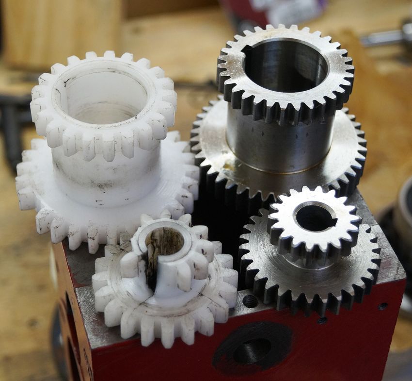
      The metal gear set arrived, quite a difference when compared to the plastic set. I probably wont get them fitted until tomorrow, it will be interesting to see how they run and sound though I,m not looking for a silent machine.

      dsc06307.jpg

      Advert
      #385243
      Ady1
      Participant
        @ady1

        I changed the plastic gears for metal ones earlier in the year

        Aluminium?

        I used T6 on my backgear and its been great

        As previously mentioned though, the plastic ones are a good weak link in a disaster

        #385246
        Hopper
        Participant
          @hopper
          Posted by Geoff Theasby on 08/12/2018 15:07:45:

          Update:

          It's the LH leadscrew bearing. Seized. Can't imagine why, it's had the same lubrication as the other end bearing.

          You should look into that, or it will just happen again.

          It could be that the leadscrew is out of alignment and thus being forced either upwards or downwards when the halfnuts are engaged and the carriage approaches the headstock end of the bed. This would put undue pressure on the bearing (and the carriage and bed ways, not to mention the poor old halfnuts.)

          Observe the leadscrew when engaging the halfnuts with lathe switched off. See if you can see deflection as the nuts engage. There should be none.

          When you put your leadscrew bearings back in place, if they have the usual bearing mounts that bolt to the bed casting, leave them finger tight, then put carriage at the left hand end of the bed, engage halfnuts and tighten up the leadscrew mount bolts at that end. Then repeat process at the tailstock end. This should set the leadscrew in line with the closed halfnuts along its full length.

          I've come across one mini/micro lathe whose leadscrew was so out of line with the bed and the halfnuts' line of travel that the carriage was jamming halfway along the bed. In that case, the leadscrew mounts were cast integral with the bed so some eccentric bushes were made up to set the leadscrew to the correct position. Fiddly but worked.

          #385288
          Ron Laden
          Participant
            @ronladen17547
            Posted by Ady1 on 12/12/2018 10:39:51:

            I changed the plastic gears for metal ones earlier in the year

            Aluminium?

            I used T6 on my backgear and its been great

            As previously mentioned though, the plastic ones are a good weak link in a disaster

            Ady, in one way its good that the plastic gears act as a weak link but what is not so good is that the weak link is in the wrong place i.e. inside the head. Having to break the machine down to remove the head and then having to strip the head is far from ideal.

            I am hoping that the steel gears will be a fit and forget and using Jasons idea of a poly belt adjusted with a little slack will offer a weak link but outside of the head. Yes I will need to make a new motor and layshaft pulley to suit the belt but hopefully that wont be a problem.

            What I am annoyed about is me breaking the lathe in the first place, having stalled it (twice) whilst parting off, though I doubt I am the first and guess I wont be the last.

            Ron

            Edited By Ron Laden on 12/12/2018 14:27:59

            #385428
            Ron Laden
            Participant
              @ronladen17547

              The lathe is back together with the metal gears fitted, it is a bit more noisy compared to the plastic gears but not horrendous and I am happy with it. A couple of things I sorted with it stripped down, one of the three small wires to the DRO sensor had broken, must have happened when I removed it. Looking at the solder joints they were pretty feeble so I resoldered all three. The motor was around 10 degrees or more off the horizontal when mounted with the belt riding to one side of the motor pulley. On refitting I adjusted and aligned the motor with the belt running central on the pulleys.

              Its good to have the low speed range back, the drive is still on the timing belt but I need the lathe running to make the two new pulleys for the poly belt.

              #385446
              Ron Laden
              Participant
                @ronladen17547

                Just noticed that I have gained a few revs, the DRO always read around 2505 in high range, it now reads 2610.

                Must be the new gears I cant imagine its anything else.

                #385455
                not done it yet
                Participant
                  @notdoneityet

                  That is at the top end. What about the minimum attainable? Low range might be different, too. Might be a case of roundabouts and swings!

                  #385459
                  Geoff Theasby
                  Participant
                    @geofftheasby

                    Thank you, Hopper. The lathe is back together, but I have to replace the leadscrew gear (stripped teeth). I bought a set of metal gears, but the one needed was bored too small for my leadscrew, and the keyway is too small. I opened up the bore, and am filing out the keyway to suit the key. Otherwise, everything's fine.

                    I shall align the leadsrew as suggested, the bearings bolt on to the bed.

                    Geoff

                    #385462
                    Ron Laden
                    Participant
                      @ronladen17547
                      Posted by not done it yet on 13/12/2018 14:02:18:

                      That is at the top end. What about the minimum attainable? Low range might be different, too. Might be a case of roundabouts and swings!

                      Low range bottom end goes down to 11 rpm but I suspect around 30-35 rpm to pick up some torque.

                      #385476
                      JasonB
                      Moderator
                        @jasonb

                        You could always play about with your new pulley sizes to get a bit more mechanical advantage at lower speed, as you say with the motor running at snails pace you can easily stall the spindle.

                        #385478
                        SillyOldDuffer
                        Moderator
                          @sillyoldduffer
                          Posted by Ron Laden on 13/12/2018 09:55:28:

                          The motor was around 10 degrees or more off the horizontal when mounted with the belt riding to one side of the motor pulley.


                          A fair wallop of force would have been applied to the motor via the belt in the short time before the plastic teeth in the gearbox broke. The crash might well have pulled the motor sideways. The mounting bolts allow movement for alignment purposes and aren't designed to hold strong sideways forces. Likely a good thing: if the motor hadn't turned on the mounting you might have bent the axle or put a ding inside one or more bearings. Shock loads can do surprising damage.

                          A slight worry about fitting metal gears is answering the 'what breaks instead' question. 3D-CAD packages often have force modelling capability. Anyone know if it's possible to model the forces experienced by a crashing mini-lathe with one of them? Could it be done in Alibre Atom3d?

                          Dave


                          Edited By SillyOldDuffer on 13/12/2018 15:18:18

                          #385494
                          Ron Laden
                          Participant
                            @ronladen17547
                            Posted by JasonB on 13/12/2018 15:06:39:

                            You could always play about with your new pulley sizes to get a bit more mechanical advantage at lower speed, as you say with the motor running at snails pace you can easily stall the spindle.

                            Oops, sorry the 11 rpm figure is running in reverse, in forward it is 32 rpm and seems to have some torque but how much I dont know, I could do a test to get some idea. Jason, thats a good idea, it had crossed my mind whether to reduce the motor pulley or increase the layshaft pulley or maybe both. There is plenty of top end speed so reducing that is not a worry but gaining some advantage at the bottom end speeds should be worth having.

                            Ron

                            #385502
                            Howard Lewis
                            Participant
                              @howardlewis46836

                              Sounds like your mini lathe was made by Real Bull, with a 4mm keyway, rather than the Seig machines with 3mm. So you have very little material to file away, only 0.5mm all round.the keyway. Obviously more, if you have to open up the bore. In which case it might be worth making up a 4mm tool with which to broach the wider keyway.

                              Howard

                              #385509
                              Ron Laden
                              Participant
                                @ronladen17547
                                Posted by Ron Laden on 08/12/2018 07:58:20:

                                Having no experience of multi vee belts, this is what I am thinking but please shout if I have it wrong. I am guessing that the depth of the rib grooves in the pully will need to be cut just shy of the depth of the belt rib, too deep and the belt at the base of the ribs will contact and the ribs wont..?

                                Ron

                                Is anyone with experience of the multi vee belts and pulleys able to confirm my thinking above. It seems obvious to me that the fit of the belt to the pulley should be as above but it would be nice to have it confirmed or otherwise.

                                Edited By Ron Laden on 13/12/2018 19:20:27

                                #385512
                                Jeff Dayman
                                Participant
                                  @jeffdayman43397

                                  Hi Ron, if you google "Gates poly v pulley dimensions" or "Gates poly v pulley profile" or the like, you may find the design guide Gates originally published for their poly V belts and pulleys. There used to be full data in it about pitch, angles, diameters etc to enable cutting exact fit pulleys. Sorry I don't have the paper version any more or I would scan and post it. The Gates Rubber Co may help if you enquire. Forgot to mention I designed all sorts of drives with this system and also Gates PGGT synchronous toothed belts when I worked for a large US based photocopier company years ago.

                                  Edited By Jeff Dayman on 13/12/2018 19:39:08

                                  #385513
                                  JasonB
                                  Moderator
                                    @jasonb

                                    I think you want the Vee of the valley to go to full depth but have flat tops to the crests, my thinking is the belt won't go right down into the vee so will not bottom out and as the tops of the vee are blunt they won't go all the way into the belt. So you will only have flank to flank contact.

                                    Probably been in MEW at some time maybe someone who takes it could direct you to an issue number.

                                    #385515
                                    not done it yet
                                    Participant
                                      @notdoneityet

                                      The drive on any V belt should be on the sides, not on the bottoms, or tops, of each element.

                                      #385516
                                      JasonB
                                      Moderator
                                        @jasonb

                                        Ron, look at MEW 246, it is as I said.

                                        #385530
                                        Ron Laden
                                        Participant
                                          @ronladen17547

                                          Thanks guys

                                          Jeff got some good detail from the Gates site, thanks for the that.

                                          Jason thanks for the advice and pointer to 246, just what I needed.

                                          Ron

                                          #385739
                                          Ron Laden
                                          Participant
                                            @ronladen17547

                                            Having had a measure up for the new poly vee belt pulleys I need to make, it is not possible to change the ratio (apart from a small amount)  to gain a bit more mechanical advantage for the bottom end. The layshaft pulley is 45mm and it could be increased to 48mm but no more as it would clash with the spindle spacer, I would have liked to increase it to say 55mm but there isnt the space. Also the recommended minimum pulley diameter for the belt is 20mm and the motor pulley is close to that now. So I will have to stick with the current ratio in fitting the new belt drive.

                                            However if one was to get a bit more adventurous it would be possible to change the layshaft pulley to a gear and fit an intermediate stepped combination gear/pulley between the motor and layshaft. It would mean making a bracket and spindle for the intermediate which could be fitted to the rear face of the head, there isnt the space to fit it within the current assembly. I can see that working quite well and it could offer ratio options but I dont think I will go there just at the moment.

                                            Edited By Ron Laden on 15/12/2018 09:20:36

                                            #386099
                                            Ron Laden
                                            Participant
                                              @ronladen17547

                                              Picture below of my old thread angle gauge, can you get similar with angles not thread related, one with 40 degrees would be ideal. I found one with a single 40 degrees but it is from the States and carriage is £17.

                                              I have to make a lathe tool for the poly vee pulleys and would like to get the angle as good as possible. If nothing is available then I will have to make something but I dont have much in the way of tooling re measuring/setting angles, not accurately anyway.

                                              dsc06324.jpg

                                              #386101
                                              JasonB
                                              Moderator
                                                @jasonb

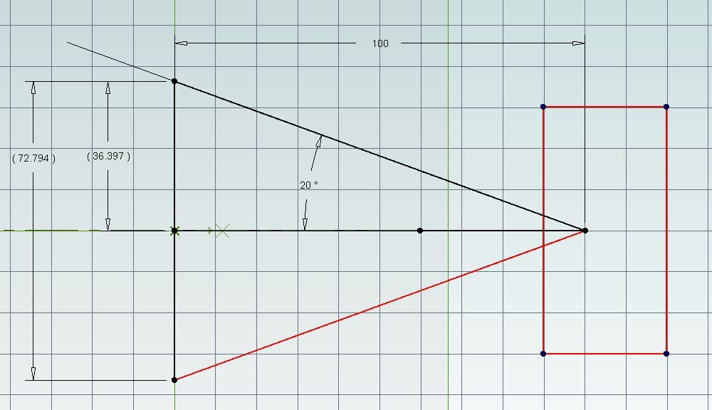
                                                For a one off why not drawn it out on a bit of stiff paper or light card then use a stanley knife to cut out the vee and make a little rectangular tool.

                                                Simple if you put a line at right angles to your papers edge 100mm long, then mark 36.4 or 36.5 would do each side and make the triangle.

                                                40deg.jpg

                                                #386104
                                                Ron Laden
                                                Participant
                                                  @ronladen17547

                                                  Typical me, complicating things, thanks Jason I have some decent graph paper which I can paste to some thin card. I think I was getting a bit hung up on how good the angle needs to be, using the above it should be pretty close anyway for making the tool.

                                                  Edited By Ron Laden on 17/12/2018 14:12:21

                                                  #386105
                                                  ega
                                                  Participant
                                                    @ega

                                                    Ron Laden:

                                                    Axminster do various angle gauges including one by Veritas at £7.20.

                                                    Another idea would be to turn a 40 deg groove in a piece of stock using acute angled left and right hand tools and setting the topslide to 20 deg either way; that method would allow you to make gauges to a variety of angles.

                                                    #386115
                                                    Journeyman
                                                    Participant
                                                      @journeyman

                                                      Ron, you can apparently buy insert tooling for cutting these pulley profiles. Never tried one so don't know how easy to find or use. Found a link to an ISCAR Insert page.

                                                      John

                                                    Viewing 25 posts - 51 through 75 (of 163 total)
                                                    • Please log in to reply to this topic. Registering is free and easy using the links on the menu at the top of this page.

                                                    Advert

                                                    Latest Replies

                                                    Viewing 25 topics - 1 through 25 (of 25 total)
                                                    Viewing 25 topics - 1 through 25 (of 25 total)

                                                    View full reply list.

                                                    Advert

                                                    Newsletter Sign-up