Milling vice expected accuracy

Advert

Milling vice expected accuracy

Home Forums General Questions Milling vice expected accuracy

Viewing 23 posts - 1 through 23 (of 23 total)
  • Author
    Posts
  • #28657
    Neil Lickfold
    Participant
      @neillickfold44316

      Poorly made vice repair

      Advert
      #593084
      Neil Lickfold
      Participant
        @neillickfold44316

        I have a milling machine with a Free vice that was part of a package deal some 12 years ago. The owner said it needed these shims to try and square up the vice and he did not use it much due to it not being accurate. I have stripped it down over the weekend. It has no name brand on it to be seen. It looks like a Vertex vice but is not the quality of the only vertex vice I have seen.

        The base is not flat nor is it parallel , with a micrometer has an error of up to 0.2mm .

        The fixed jaw block is not parallel or square to the keyway slot. It is a good fit to the keyway though and the key fit to the base is good. They got that part right. The fixed block error is around 0.15mm out of parallel from the bottom to the top. And then over the length has a similar error of 0.18mm.

        The moving jawblock has similar errors to the Fixed jaw block but over a loner distance.

        When the vice was all assembled, it all looked very nice, with hardened jaw insert that all aligned up about even for height and width when closed, but did have a funny looking gap at the bottom.

        I have done No investigation to the swivel base that has come with the vice.

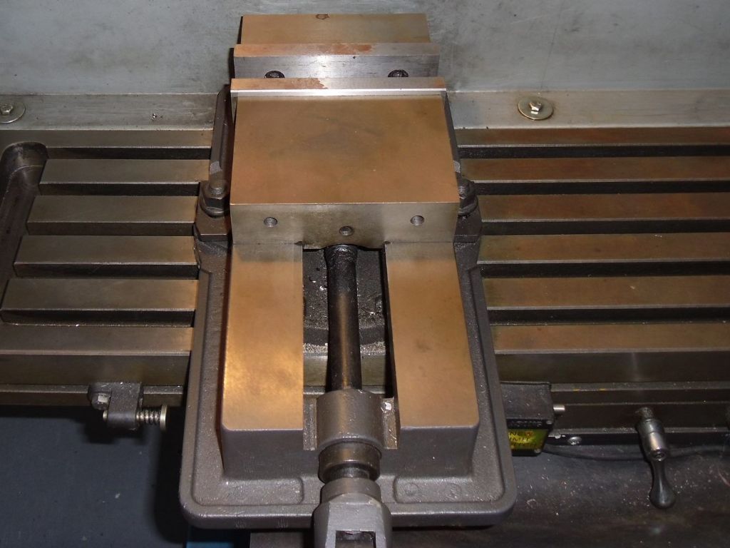
        My question is, what is the normally acceptable run out on a milling vice for hobby use? This is a large vice with the Jaw width being 6 inches and has a swivel base as well. I found a picture of the vice.

        Neil

        milling-vice.jpg

        #593095
        SillyOldDuffer
        Moderator
          @sillyoldduffer

          Better than that Neil. I own two hobby vices and they're both flat so far as I can tell.

          However, I don't expect mine to align accurately with the table slots. Instead, I fine tune the alignment with a Dial Indicator on the fixed jaw by tapping the loosely nipped vice with a mallet, tightening up when it's straight. There's room to align the vice because my bolts aren't a tight fit in the slots. I can get the fixed jaw straight better than 0.01mm over 100mm, or at least what my DI believes is 0.01mm. Pretty good anyway.

          I'm not sure your other measurements matter. The vice should be OK provided it's fixed jaw is aligned with the table, and it's front face is flat, and the area the work rests on between the jaws is parallel to the table.

          The funny groove sounds like a stress relieving feature. One of mine has it – makes it hard to position thin work, but annoying rather than a show-stopper.

          Dave

          #593097
          Bill Phinn
          Participant
            @billphinn90025
            Posted by Neil Lickfold on 05/04/2022 20:34:34:

            My question is, what is the normally acceptable run out on a milling vice for hobby use?

            Neil


            It depends really over how great a distance you're measuring and what the end user himself deems acceptable for his own purposes.

            Some of the vices sold for hobby use quantify the level of precision you can expect them to meet.

            Eta: I'm not sure what Neil and Dave mean by the funny gap/groove. Could we see a picture? We're not talking about the swarf gutter* beneath the fixed jaw, I take it?

            *I'd always assumed it was primarily a swarf gutter and not a stress reliever. Maybe I'm wrong.


            Edited By Bill Phinn on 05/04/2022 21:22:08

            #593098
            Neil Lickfold
            Participant
              @neillickfold44316

              Thanks Bill. Over the height of the vice I have the error is 0.15mm over the 40mm distance. The left to right height error is 0.2mm so you cant place a part and mill it parallel.

              The chart shown is good information. So will go about trying to get it all sorted then and repaired. Looks to being a long project to go through the whole lot.

              #593099
              Neil Lickfold
              Participant
                @neillickfold44316

                Thanks Bill. Over the height of the vice I have the error is 0.15mm over the 40mm distance. The left to right height error is 0.2mm so you cant place a part and mill it parallel.

                The chart shown is good information. So will go about trying to get it all sorted then and repaired. Looks to being a long project to go through the whole lot.

                #593109
                Mark Rand
                Participant
                  @markrand96270

                  I've got a pair of 6" no name milling vices that I sorted out and made into a matched pair. It's fairly easy to mill the base and ways both flat and parallel and to mill the face of the jaws perpendicular and parallel (and to mill the tops of the fixed and mofing jaws flat and parallel). Once you've done that, it's worth paying attention to the angle on the feed nut that the moving jaw slides over to pull it down when locking. Also the faced-off ball that is supposed to slide on that slope might be less than perfect. a bearing ball from the likes of simplybearings can be faced off to improve this.

                  Doc of 'The Whiteboard' fame has produced a very good writeup of some of the things you are likely to come across:-

                  **LINK**

                  Edited By Mark Rand on 05/04/2022 22:04:05

                  #593111
                  Huub
                  Participant
                    @huub

                    I milled my own parallels and marked one side so that I can place them back the way they are milled. Heigth is now withing 0.01 mm.

                    I removed the vice jaws, and milled the vice so now the jaws are square to the mill.

                    For aligning the (80 mm) vice I made a spacer. The back of the spacer was clamped against the flat Z-axis support of the mill. Then the front of the spacer was milled. Now the front is perpendicular to the X-axis of the mill. When I use this spacer for aligning the vice, it is 9 of 10 times within 0.02 mm measured over 60 mm. That is accurate enough for most of what I make.
                    If I need it to be more accurate, I align the vice using an indicator to get it within 0.01 mm.

                    Last year I bought a 100 mm Vice for € 100 from Paulimot Germany. The left and right side of the vice (base) differ about 0.04 mm. That is quit much in my opinion.
                    If I need a new vice, I will try Vertex, that is (hopefully) better in quality.

                    You should also check the alignment of the milling head in X, Y and Z direction before you seriously start accurate milling.

                    #593115
                    Paul Lousick
                    Participant
                      @paullousick59116

                      If " The base is not flat nor is it parallel" machine it flat. First, tram the mill table so it is square to the head and mount the vice base upside down on 123 blocks (or similar) and take a light cut to make it parallel.

                      " The fixed jaw block is not parallel or square to the keyway slot ". (Assuming the jaws are parallel), Remove the fixed jaw and machine the base to make it parallel to the mill.

                      The fit of the key in the vice to the mill base will always be a loose fit (although a snug fit is ideal, otherwise it will be difficult to install). Even if there is a lot of slop, the vice can be made square to the mill by pushing the vice against the side of the slide keyway before clamping it down.

                      #593157
                      Henry Brown
                      Participant
                        @henrybrown95529

                        I have a similar vice and I did exactly what Paul suggested above.to get its thickness parallel. My table slots aren't particularly good so I took a little of the locator blocks to allow me to set the vice square to the table by using a parallel to clock onto nipped into the vice, its no problem for me as the vice stay put for 90% of the time.

                        #593185
                        Hopper
                        Participant
                          @hopper

                          I like to work comfortably within a thou (or 0.025mm or whatever it is) when turning or milling so the vice would have to be at least that precise. Preferably more. If you could get it within a few tenths of a thou would be ideal but not easy.

                          I doubt you will achieve those tolerances of the Arc Euro vices at 0.003mm per 100mm etc on a home milling machine. Those vices are ground finish, which is a whole other ballgame.

                          #593191
                          Neil Lickfold
                          Participant
                            @neillickfold44316

                            I got the base ground flat to better than 0.01mm so am happy with that aspect. The top part was quite true, only about 0.03mm or so deviation. But the base took 0.3mm to clean up in the end. I also ground the sliding jaw parallel surfaces and the fixed jaw parallel (The one that is fixed with the keyway) and the top side. While at it made them both the same thickness. After cutting down the pressed in 10mm keys, I just discovered that they are on two different angles and neither makes sense as to why it is this way.

                            Is there any specific reason for making the keys on different angles ? The only one I could think of was to preload the fit of the fixed jaw to the vice. It will also explain why the original keys were so radiused on the top of them.

                            This project is not really worth it, I should just go and by one of the better made better materials, branded vice. But I have started now and don't like throwing away things that could be salvaged.

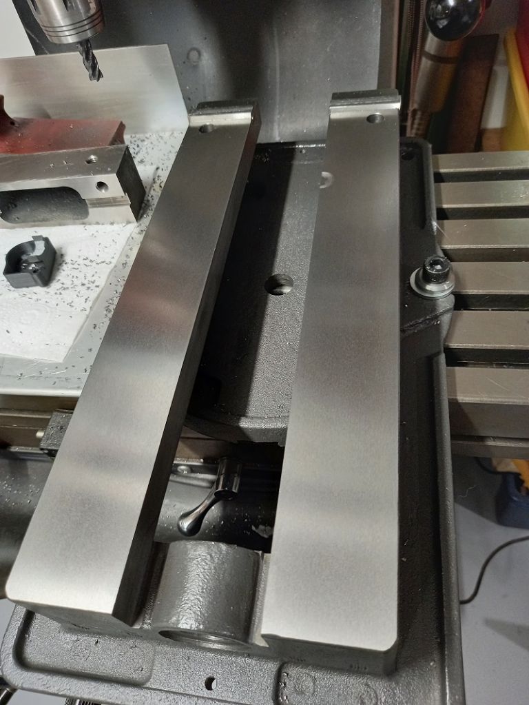
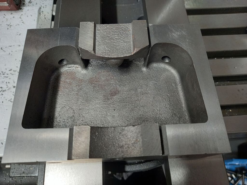
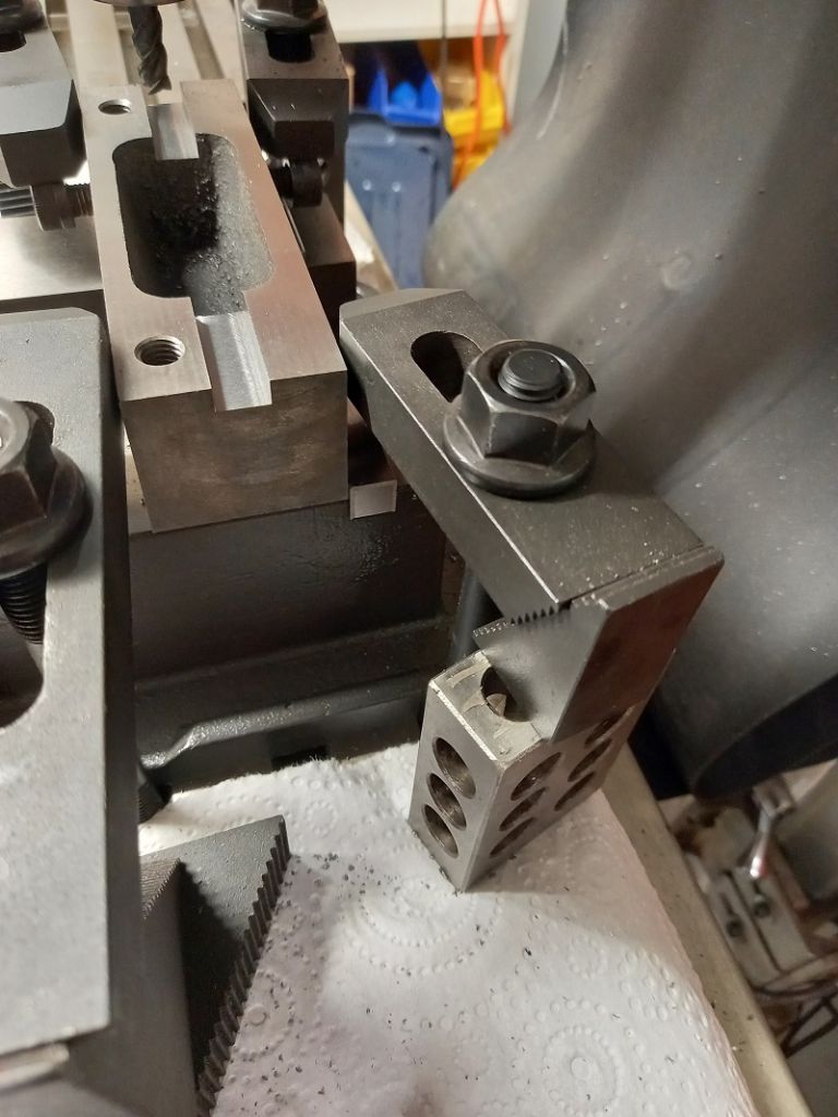
                            Here is a picture of the base and the fixed jaw. Another is of the moving jaw that required 0.07mm to clean up the underside that was a mill or flycut finish in a hurray.

                            fixed-jaw-keyway-1.jpg

                            Ground moving jaw-Minimum cleanup. Milling marks as a witness still. Vice edges will be left sharp as a wiper against the swarf.

                            ground-moving-jaw.jpg

                            Neil

                            #593194
                            Hopper
                            Participant
                              @hopper

                              Nice. Do you have your own grinder? Or at work? Very handy to be able to do.

                              Yes better to fix than buy another. You never can be quite sure what you will get these days.

                              #593197
                              Neil Lickfold
                              Participant
                                @neillickfold44316

                                I did it after hours on the works grinder. They have 2, a small one that has a nice set if magnetic blocks, and a bigger one that is most often used. The rest of the work I will do at home on the refurbished quill HM50 mill. Looks like I need to look at the gibs all round for the mill too at some point.

                                Thats a good point that I will know what I have actually got too. It may have to only be used on finishing work or light duty stuff to help it keep its accuracy.

                                Neil

                                #593202
                                Hopper
                                Participant
                                  @hopper

                                  Good idea.

                                  If it's like my mate's HM50 or 40-something mill, check the column for vertical/square to table etc too, as well as just head tram etc. And he had to dig a bag of casting sand out of the internal cavities too. Luckily he did that before running the mill so no damage was done. Once he got it sorted it works very nicely.

                                  #593206
                                  David-Clark 1
                                  Participant
                                    @david-clark1

                                    Should easily be within a thou both ways. I would remove the swivel base and put the vice flat on the mill bed. The funny gap is probably so the cutter does not hit the cast iron close to the fixed jaw. You can9 fill it with araldite and machine it flat. If you don’t want to machine the fixed jaw seating vertical, you can put a bit of shim at the top or bottom of the fixed jaw so it is less than a thou out vertically.

                                    #593222
                                    old mart
                                    Participant
                                      @oldmart

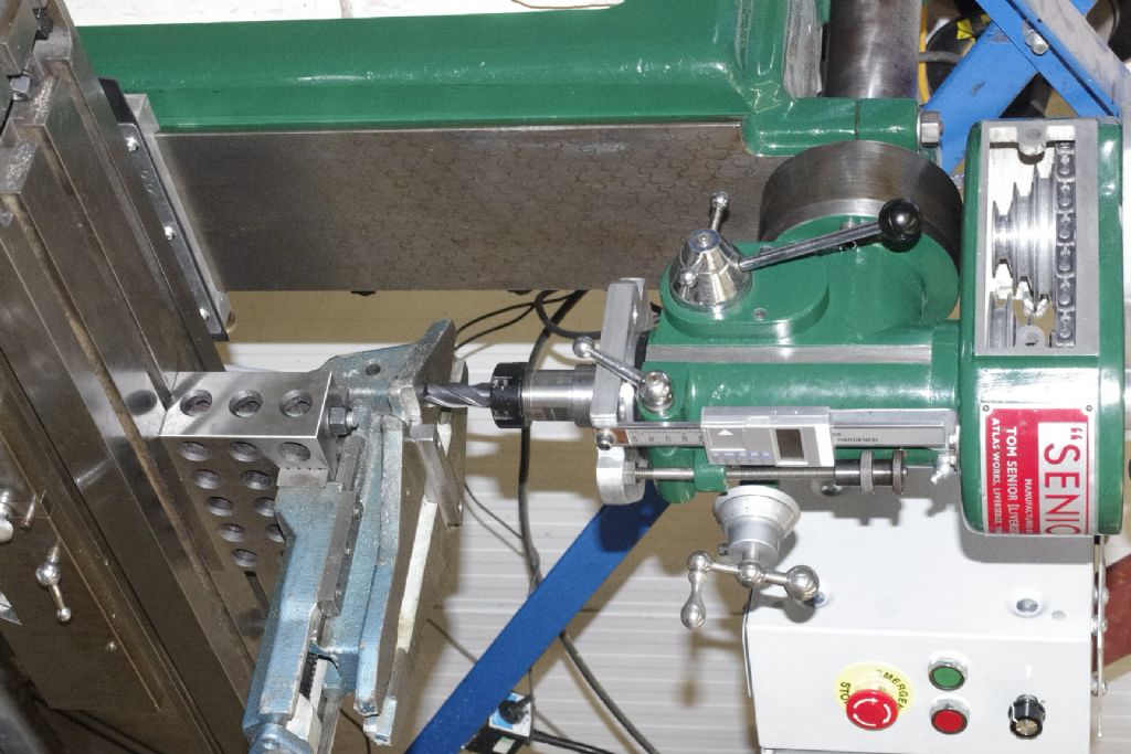
                                      The solution if you don't have access to grinding is to set up a 1-2-3 block, or better still a 2-4-6 block parallel to the X axis and clamp the vise upside down to the block. Put parallels on top of the block if the jaws are too deep. _igp2463.jpgThis should square up the rear jaw and vise bed. Then skim the underside of the vise, having removed the swivel base first. This should be fine for home shop use, most vises are only milled underneath.

                                      #593264
                                      Neil Lickfold
                                      Participant
                                        @neillickfold44316

                                        Thanks for the input . All ideas are appreciated.

                                        Once I get the top side sorted, this is how I intend to do the key alignment for the base of the vice. I still need to get the top sorted yet. What I am going to do for the top fixed jaw is to just put it back like it was, and mill a reference clean up cut while I have the run of the base true to the table. Then place the jaw onto the angle plate and cut the jaw parallel and square to that reference face and then make it parallel. Will also square up the end faces and tap them for setting stops etc as well. After seeing Stefan's video and how he has tapped holes in the top of the vice, to hold round stock secure etc, I will do the same and then make some covers for the holes when not in use.

                                        With these soft castings, I can see why the old school millers used 4 clamps to hold the vice and not the slot and 2 tee nuts.

                                        Neil

                                        Edited By Neil Lickfold on 06/04/2022 20:50:04

                                        #593606
                                        Neil Lickfold
                                        Participant
                                          @neillickfold44316

                                          Even the hard jaw sets are out of parallel buy 0.06mm over a short width of 44mm. One jaw is .04 short one side and .05 short the other side, so kind of like a twisted board. But one side feels flat , while the other side feels warped and rocks on the table. It looks like the only part that has not needed attention is the screw and nut. Lucky that I have access to a surface grinder to be able to fix the hardened jaws. One test I will do is to see how much it all moves when it is done up with a block in the vice. The error on the fixed jaw is going the wrong way to compensate for any load on the vice tightening up though. It is larger at the base side than the top side by about 0.04mm over it's 40mm height.

                                          As an update, the keyway will get recut to the larger 12mm key stock and then an extra set of screws will clamp the fixed block down , but will be M10 capscrews drilled from the top. Just can't be bothered turning over the vice to drill and counter bore the holes from the bottom through what would be a partially interrupted counterbore as well.   

                                          Edited By Neil Lickfold on 08/04/2022 21:59:31

                                          #593695
                                          Howard Lewis
                                          Participant
                                            @howardlewis46836

                                            In terms of cost / time effectiveness, this may be a poor one.

                                            BUT, when you have finished, you will have the satisfaction of having made a good silk purse out of what started as a sow's ear.

                                            And that will make you happy for a long time, and probably every time that you use it.

                                            You cannot put a price on being confident that it is accurate and will do what you want consistently.

                                            Good Work!.

                                            Howard

                                            #593705
                                            Neil Lickfold
                                            Participant
                                              @neillickfold44316

                                              A decent replacement is now around $600 NZ at the moment and courier deliveries are very slow to residential addresses too. Yeah time effectiveness it is not the best option, but it does leave money in the account for other things. Will be getting a 3phase motor for the HM50 mill and vfd drive. Changing belts gets very old very quickly, especially when being used to a gearbox drive head or a variable drive head.

                                              Neil

                                              #593801
                                              Neil Lickfold
                                              Participant
                                                @neillickfold44316

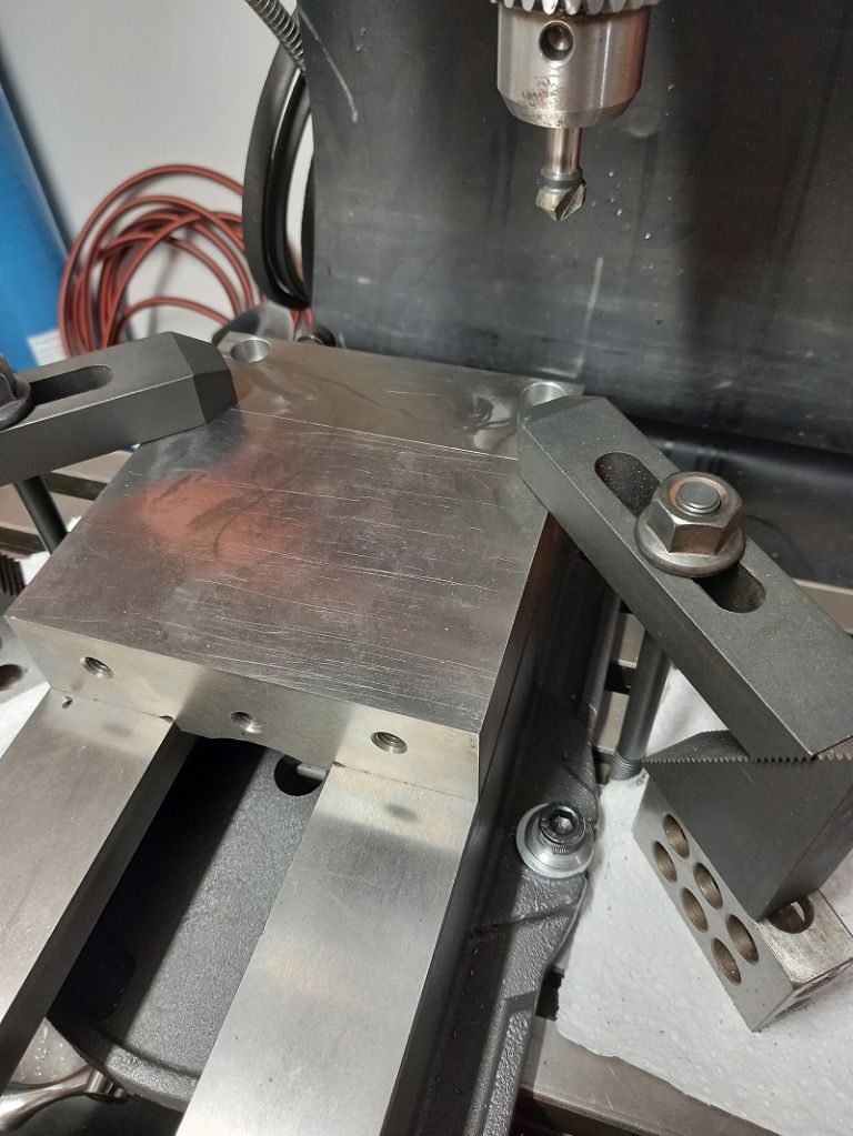
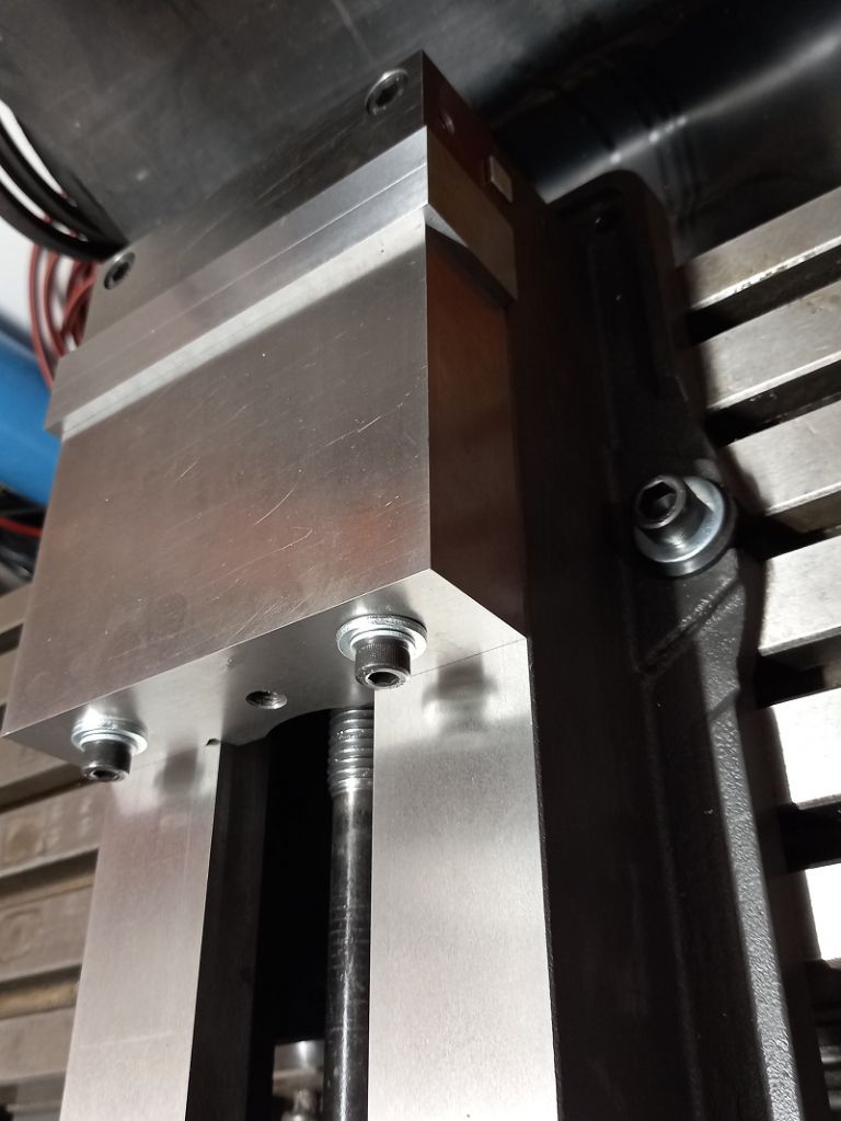
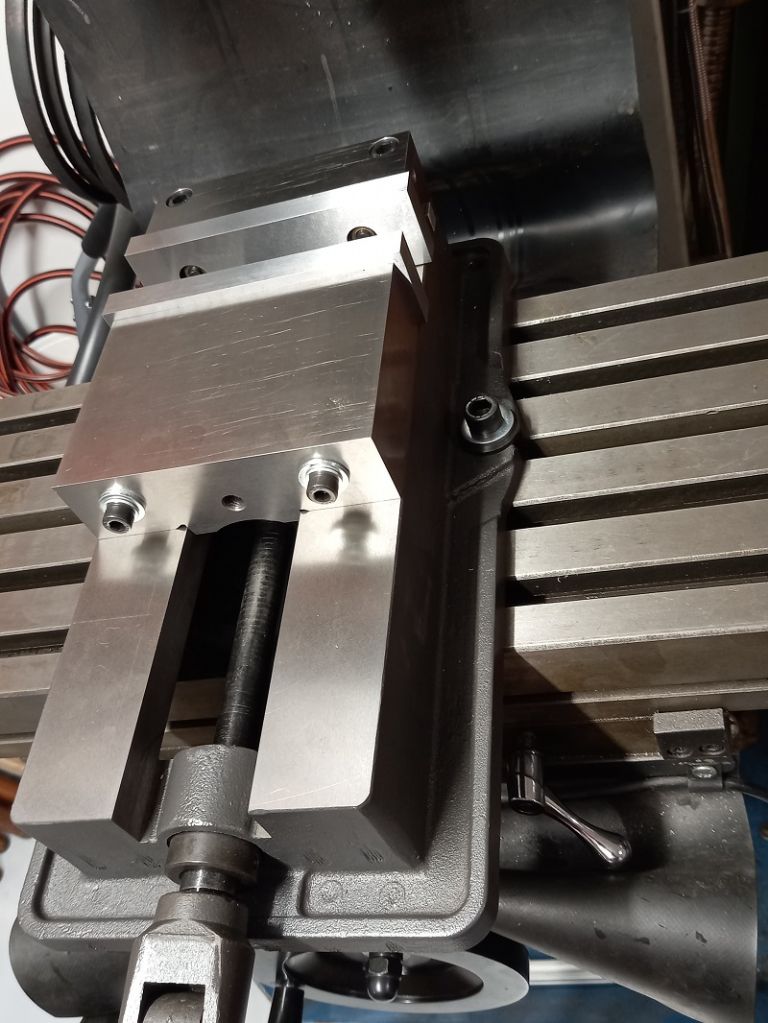
                                                Some more pictures of the rebuild.

                                                After cutting the Keyway slots to take 12mm keys in the base, upgraded the slot on the fixed jaw to take the 12mm key and used the newly made keys to be the reference for cutting the fixed jaw.

                                                upgraded-to-12mm-keyways-aligned-to-vice-body.jpg

                                                Added two more m10 hold down positions on the fixed jaw while it was all set up. To go from the underneath side was going to be too awkward.

                                                added-extra-hold-downs-with-12mm-upgrade.jpg

                                                Back bolted jaws are much easier to allow for re alignment if the jaws are swapped to one of the ends like when doing wider work holding.

                                                back-bolted-jaws-to allow-easy-alignment.jpg

                                                Finished vice with the M8 end stop holes on the side of the fixed jaw. The moving jaw and the fixed jaw are the same height for when wide stock is being held down. I still have not yet put the top clamp holes in the moving or the fixed jaw yet , like Stefan has done with his vice. I was going to wait until such a job arose and then decide on one centre clamp tapped hole or to have two holes either side of the centre. The base runs very true to the table of the mill now, and the jaw is now square to the base of the vice.

                                                finished-vice-added-side-m8-stop.jpg

                                                Neil

                                                #593802
                                                Neil Lickfold
                                                Participant
                                                  @neillickfold44316

                                                  Just a note about angle plates, if you want the most accuracy from the angle plate, the weight of the work piece need to be fully supported some where else, in my case the surface grinder table, and the plate is only there to support the side or sides that need to be in my case 90 deg angle. On a webbed plate like mine is, can handle unsupported weight but the accuracy will not be the same as being supported. This is only for very small amounts of error which is less than 0.01mm.

                                                Viewing 23 posts - 1 through 23 (of 23 total)
                                                • Please log in to reply to this topic. Registering is free and easy using the links on the menu at the top of this page.

                                                Advert

                                                Latest Replies

                                                Home Forums General Questions Topics

                                                Viewing 25 topics - 1 through 25 (of 25 total)
                                                Viewing 25 topics - 1 through 25 (of 25 total)

                                                View full reply list.

                                                Advert

                                                Newsletter Sign-up