measuring small bores

Advert

measuring small bores

Home Forums General Questions measuring small bores

Viewing 7 posts - 26 through 32 (of 32 total)
  • Author
    Posts
  • #243799
    Ajohnw
    Participant
      @ajohnw51620

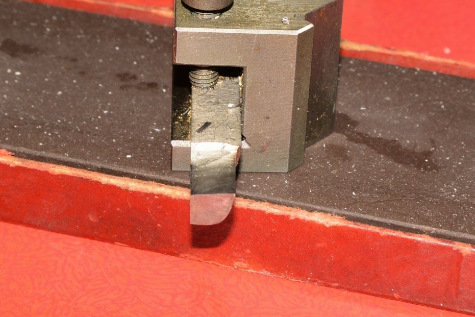
      I would use a tool something like this plus back rake with just enough sticking out of the holder and use the largest size of HSS that I could.

      semiboringtool.jpg

      No point repeating measuring methods that have been mentioned. The best way of measuring bores to the accuracy you need is a 3 point bore micrometer that has been set correctly via it's hole gauge. Some designs of those are much better than others. Long anvils help. On N6 you should also be interested in the quality of the finish – tables seem to show a tolerance of 0.01 to 0.004 mm and I would assume the outer shell of the bearing is sized to give the interference fit but you best measure and check that, Manufacturers tables sometimes give the actual hole sizes needed which would be a better alternative.

      Really to go any further there is a need to know what style of needle roller bearing you intend to use. I suspect it might be drawn cup but not sure. Some come with hardened inners etc.

      John

      Advert
      #243801
      colin hawes
      Participant
        @colinhawes85982

        I think you just need to ensure the boring tool is very sharp and that it is not rubbing below the cutting edge. The only practical way to measure small bores is to make a plug gauge , preferably with a small "nearly there" step. That's how I've done many such bearing fits.

        Colin

        #243803
        Clive Foster
        Participant
          @clivefoster55965

          As Sandgrounder suggests you'd expect a slightly flexible tool to take up its flexed position almost immediately once cutting loads are applied and stay at the flexed position for the duration of the cut. Slight variations of cutting loads due to material variations might vary the cut depth a touch as the flex responds to changing forces but that would merely mark the bore. The steady increase in flex as boring proceeded leading to bell mouthing seems counter-intuitive as the flexed boring bar is, for all practical purposes acting as a spring tool. Which are generally considered quite well behaved in outside turning duties.

          If the tool is sufficiently sharp and the cut large enough to give sensibly stable cutting loads it will behave in the expected manner. The problem in model engineering duties is that its difficult to get a small boring tool really sharp with all the right clearances. I actually did a CAD drawing showing the amount of grinding needed to get clearance on smaller holes. Generally much more than I expected. If the tool isn't really sharp and doesn't cut as well as it should it will slowly ride out of cut as boring proceeds due to the unfavourable relationship between tool angles and cut surface.

          Oversimplifying the actual force holding the tool against the surface to be cut is set by the spring of the flexed tool shank. This force has to be enough to push the tool into the work so it cuts. The actual force needed is a function of cutting edge length being less for shorter lengths of engaged edge. Clearly the minimum edge length occurs when the end of the work and the edge of the tool are mutually parallel and perpendicular to the lathe axis. Any forward slope on the front of the tool leads to the cutting edge becoming longer as the tool moves forward as the actual shape of the cut end mirrors the shape of the tool. The longer edge needs more force to hold it into the cut which the flexed tool can only provide by bending back a touch until things come into balance. It takes more force to start or deepen a cut than it does to hold it so the system never recovers back to the proper cutting depth unless there is a soft spot. If the tool is really sharp things stabilse after the initial cut so you get a mostly parallel bore. If the tool is not quite sharp enough, especially in a skiddy material, it tends to slowly ride out of the cut. With small holes, skinny tooling and not that much flex the system can't generate enough force to pull the cut back to depth so the tool slowly looses the battle to stay on size.

          An over pointed tool with the leading edge running back towards the tool post will reverse bellmouth as the chip forming action pulls the tool into cut. Theoretically it ought to be possible to find an angle where the chip stabilises the tool against bell mouthing producing a parallel bore. Good luck with that!

          Sneaking up to size with tiny cuts doesn't help matters either. The smaller the cut the sharper the tool needs to be. Near enough need a razor to reliably take off a thou! I do better setting things up right to have a decent cut to finish. But I generally do larger work on a heavier machine than most folks here.

          Clive.

          Edited By Clive Foster on 22/06/2016 11:08:16

          Edited By Clive Foster on 22/06/2016 11:09:39

          #243832
          RRMBK
          Participant
            @rrmbk

            Thanks to everyone for such a wealth of information, a couple of responses if I may.

            The tool I am using is pretty rigid and not showing obvious signs of deflection. I am beginning to suspect that the bellmouthing is something to do with an initial slight freeplay in the cross slide leadscrew. I have wound the crosslide out to the cut but it still seems to create a slight bubble of oil at the interface between the crosslide and the saddle when the cut begins.. the remainder of the bore seems fairly parallel.

            The idea is to make a simplified cannon type box where the axle is running inside a tube set into the axleboxes at either end. this is to try and stop the coal dust etc as this axle runs below the grate.

            The tight tolerance is because of the use of closed cup roller bearings which close down onto the bore / shaft when fitted so the shaft tolerance is dependant upon the outside diameter.

            I do have adjustable reamers that would do the job but I am somewhat frustrated at not being able to produce a job that should be fairly straightforward for my lathe which is Holbrook 9 " which is solid and without any significant wear issues. Or at least not that I know about !

            Once again thanks for all the help and good advice. Great to know there are so many friendly people out there willing to freely offer their help .

            #243836
            Ajohnw
            Participant
              @ajohnw51620

              Sounds like your cross slide is a little on the loose side to me. If you want to work to very close tolerance some resistance to movement is in my view essential. Otherwise the cross slide twists slightly once the cut starts.

              On the bearings it might pay you to look at the SKF catalogue and look at the tolerances and uses. There is a fair amount tolerance in the bearings themselves which doesn't leave much scope for variations in the holes they are in. What running clearances you use is up to you to some extent but they suggest C2 – C3 clearance between the shaft and bearings. I don't think they will work very well on soft shafts. Hard inner sleeves are available but that leaves no scope for altering shaft size to suit the housing. They also don't prevent end float as far as I am aware and that needs taking care of some other way.

              John

              #243841
              Neil Wyatt
              Moderator
                @neilwyatt

                Sharpness is essential. I was reminded of this recently when making a very simple bore in a bit of aluminium tube that needed to be a shake free push fit over about 35mm length.

                I used a slender 3/16" tool of d-bit form and it was producing a bell mouth. I tried different angles with no change, but as soon as I dressed the end with a diamond slip, it started cutting a parallel hole.

                Neil

                #243865
                RRMBK
                Participant
                  @rrmbk

                  Thank you A John W . your post finally pointed me in the right direction. Just to outline what I think has happened so it hopefully doesn't catch anyone else out, here goes. On this lathe the cross slide feed nut is held in place with an allen bolt through the top of the cross slide. It fixes the feed nut in place and also acts a somewhat of a backlash eliminator. Before boring I tightened up the gib screws to give a smooth stiff operation. It appears that the allen bolt had come slightly loose allowing a little movement between the feed nut and underside of the cross slide, which was disguised or hidden by the tight gib strip. Once the tool touched the work a slight take up of the free play tended to create the bell mouth.

                  Bazyle, Neil Clive and Nigel . Thank you also as your comments about tool sharpness and particularly cutting on the forward face rather than the side of the bore were particularly helpful. I think the shape I was using tended to cut more on the side and although I was taking return cuts I think Clives explanation of continuation of the problem once it has set in was most insightful for me.

                  Quick test tonight suggests a good improvement but wont be in the workshop for a week or more now due to work & other commitments. Tally Ho – onward and downward!!

                  Thank you once again all.

                Viewing 7 posts - 26 through 32 (of 32 total)
                • Please log in to reply to this topic. Registering is free and easy using the links on the menu at the top of this page.

                Advert

                Latest Replies

                Home Forums General Questions Topics

                Viewing 25 topics - 1 through 25 (of 25 total)
                Viewing 25 topics - 1 through 25 (of 25 total)

                View full reply list.

                Advert

                Newsletter Sign-up