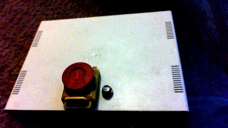
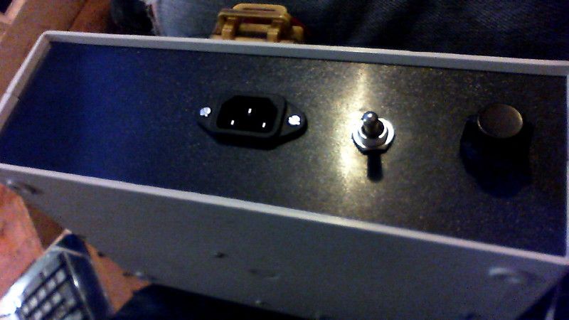
So onto the case i drilled two holes looking at the case on the far right i have the speed pot, next to it i have the fwd/off/rvs switch, then i have just to the right of the middle an iec chassis plug, this was chosen as i had some laying around gathering dust, above the socket on top the box i have the emergency switch and to the right of that i have the fuse, i put the fuse on the top as its easier to get at should it blow. at the same time i have put the fuse into the live side as per the(mini lathe pcb posts on here).
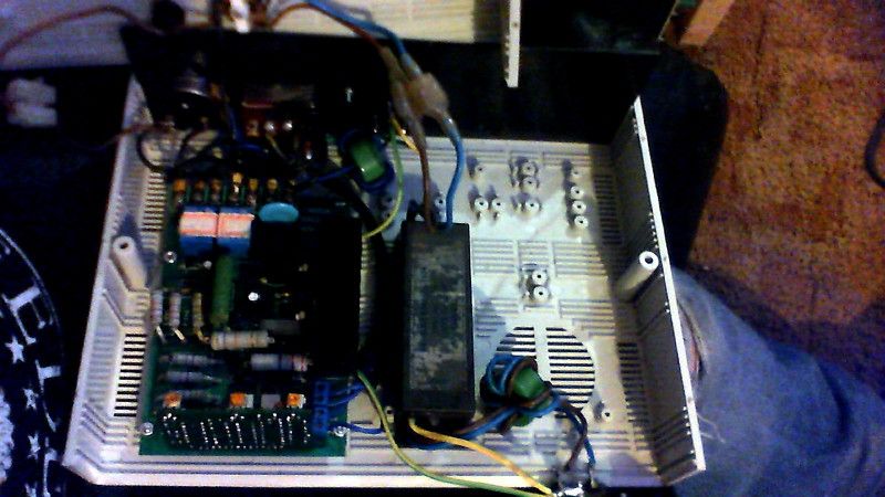
Inside the case at the far right i have mounted the board with some 6mm stand-offs to allow a bit of air to circulate, the 7 screw terminals on the board are facing the front and connect directly to the switches, mounted to the left of the board is the mains filter and another chassis socket is mounted on the rear for the mains input which is a standard kettle lead, i would have used an ordinary strain relief grommet here but i prefer using a standard set of connectors, i have a spare kettle lead ready for the motor(as im using that type of connector for the motor) , i cant connect that fully yet as the rear motor case is starting to crack(need to find a supplier).
Everything was deliberately placed as far to the right as possible as i have enough room on the front panel to fit either an lcd or 7 segment displays and its associated pcb as i intend to fit a speed display, and if i can get the software sorted an lcd display showing other data like cutting speeds in feet per sec etc. but that's a long way off
Internal wiring is as follows i have soldered flying leads to the emergency switch and these connect as standard to the mains filter and can be unplugged to remove the lid, i have soldered another flying lead to the other neutral on the emergency switch this screws to the control board, then the live goes from the emergency switch to the fuse ,then to the on/off speed control pot this is connected by a chocholate block temporarily ( i've ran out of lucar terminals and will change them at a later date).
Earthing is connected to the input side from the mains filter, the FWD/RVS switch is metal and must be earthed this is connected to the output socket and the input and output sockets are connected together via an earth cable, and the motor via the output cable and also from the lathe to the motor, this must be done as all the earth connect on the lathe but with a remote box has to be done this way, so if you decide to do this mod YOU MUST CONNECT BOTH SOCKETS VIA THEIR EARTH TERMINALS. (please note if you arnt competent to do this find someone who is.
I haven’t refitted the motor to the lathe yet but have tested it on the bench, the motor no longer runs on its own or growls, so if you get some weird behaviour on your lathe motor remove the board and give it a good scrub reassemble and try again, I wonder how many of these boards burn out due to contamination.
My next mod will be putting a needle roller bearing at the far end of the lead screw with a thrust race bearing on the inside of the block, if that works out then the same on the other end, also will fit a thrust race to the rear of the top-slide screw.
Regards
Inee
Sub Mandrel.


