Larger VFD/Motors
Larger VFD/Motors
Home › Forums › General Questions › Larger VFD/Motors
- This topic has 95 replies, 29 voices, and was last updated 21 May 2019 at 11:26 by
SillyOldDuffer.
-
AuthorPosts
-
9 May 2019 at 07:27 #408341
 Robert Atkinson 2Participant@robertatkinson2
Well I was trying to keep it simple and it's not relevant to the original question. Lets not go into vector control other than to say it certainly does not have a fixed output voltage and any set-up should not exceed the motors rated maximum voltage regardless of the control scheme.
Questions on vector control could fill several new threads.Robert G8RPI.
Edited By Robert Atkinson 2 on 09/05/2019 07:31:30
9 May 2019 at 12:57 #408407SillyOldDuffer
Moderator@sillyolddufferPosted by Andrew Johnston on 07/05/2019 11:17:00:Posted by SillyOldDuffer on 07/05/2019 10:36:40:I find it hard to get my head round what the effects of starting and loading a 3-phase motor powered by a VFD might be on current flowing on the input supply. On average – I think! – a motor working at a steady rate is a good fit to this sort of analysis:
The problem is that one still needs to account for phase angles, even with averages. So ideally one needs to use complex numbers, or as I prefer to call them two dimensional numbers.
If you're going to do some measurements, and I'd be interested to see the results, you'd be better off (and safer) using a current transformer, like these:
The datasheets are worse than useless and the frequency range is a bit limited. But they'll give an indication of the current waveforms, and it's a lot safer than playing with high side current sense resistors. You may want to check the maximum input voltage wrt earth before you go connecting to the mains.

Andrew
Thanks for the hint on current transformers – I shall order one.
Meanwhile, I've been exploring my oscilloscope's math functions. No sense made of it whatever until I eventually spotted the math range was set to 1 picoVolt per division! Then took me ages to work out from the manual how to change it. All obvious when you know, baffling when you don't.
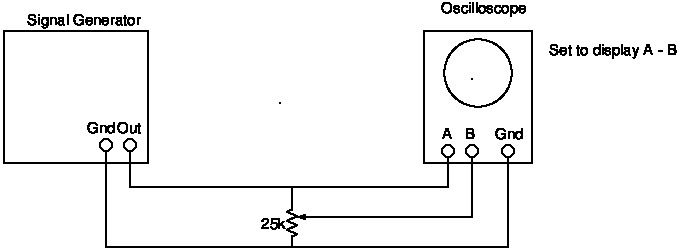
In the learning phase I'm avoiding mains voltages for safety reasons. I was able to calculate the actual value of a random setting of the potentiometer with this set-up:
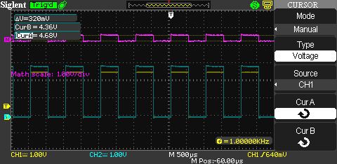
and this display:
I used the oscilloscope's square wave calibration output rather than a sine wave but same sums. Hard work compared with measuring resistance directly with a multimeter, but this is proof-of-concept for the next stage.
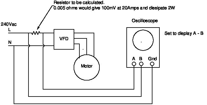
Plan A looked like this:
This would allow the start-up current to be calculated accurately at any point of time over a few seconds, but setting up is slightly hairy because the measurements are taken at full mains voltage. Not frightened of that, but Andrew's 'current transformer' suggestion is both safer and likely to give indicative results with less fuss. It's not necessary to use the oscilloscope's Maths functions at all. (Now I've wasted an hour learning how to use them.)
As usual I am neglecting priority domestic duties in favour of this interesting diversion.
Dave
9 May 2019 at 14:07 #408427Anonymous
Posted by SillyOldDuffer on 09/05/2019 12:57:47:As usual I am neglecting priority domestic duties in favour of this interesting diversion.
Time spent learning is never wasted, even if you don't know when you might make use of the new knowledge.
Another potential disadvantage of using the maths function of the 'scope to measure a high side sense resistor is to do with common-mode rejection ratios. Have a look at the maths of instrumentation amplifiers as an excuse to further ignore the domestic duties. There is a classic design for a nifty three opamp configuration that provides very good common-mode rejection while not requiring precision resistors.
Andrew
9 May 2019 at 22:27 #408506 Robert Atkinson 2Participant@robertatkinson2Posted by SillyOldDuffer on 09/05/2019 12:57:47:Posted by Andrew Johnston on 07/05/2019 11:17:00:Posted by SillyOldDuffer on 07/05/2019 10:36:40:
I find it hard to get my head round what the effects of starting and loading a 3-phase motor powered by a VFD might be on current flowing on the input supply. On average – I think! – a motor working at a steady rate is a good fit to this sort of analysis:
The problem is that one still needs to account for phase angles, even with averages. So ideally one needs to use complex numbers, or as I prefer to call them two dimensional numbers.
If you're going to do some measurements, and I'd be interested to see the results, you'd be better off (and safer) using a current transformer, like these:
The datasheets are worse than useless and the frequency range is a bit limited. But they'll give an indication of the current waveforms, and it's a lot safer than playing with high side current sense resistors. You may want to check the maximum input voltage wrt earth before you go connecting to the mains.

Andrew
Thanks for the hint on current transformers – I shall order one.
Meanwhile, I've been exploring my oscilloscope's math functions. No sense made of it whatever until I eventually spotted the math range was set to 1 picoVolt per division! Then took me ages to work out from the manual how to change it. All obvious when you know, baffling when you don't.
In the learning phase I'm avoiding mains voltages for safety reasons. I was able to calculate the actual value of a random setting of the potentiometer with this set-up:
and this display:
I used the oscilloscope's square wave calibration output rather than a sine wave but same sums. Hard work compared with measuring resistance directly with a multimeter, but this is proof-of-concept for the next stage.
Plan A looked like this:
This would allow the start-up current to be calculated accurately at any point of time over a few seconds, but setting up is slightly hairy because the measurements are taken at full mains voltage. Not frightened of that, but Andrew's 'current transformer' suggestion is both safer and likely to give indicative results with less fuss. It's not necessary to use the oscilloscope's Maths functions at all. (Now I've wasted an hour learning how to use them.)
As usual I am neglecting priority domestic duties in favour of this interesting diversion.
Dave
As shown your set-up is likely to damage your oscilloscope if it dosen't electrocute you. It will certainly trip any RCD you have on the circuit because you are connecting the neutral to ground via the oscilloscope.
As a minimum you need to use proper 600V CAT II high voltage 'scope probes and an isolation transformer. The proper way to do this is with isolated differential probe, a specialised oscilloscope with isolated inputs or a power analyser.It's really not something you should be playing around with unless you really need to and take precautions.
Robet G8RPI.
10 May 2019 at 11:47 #408584Anonymous
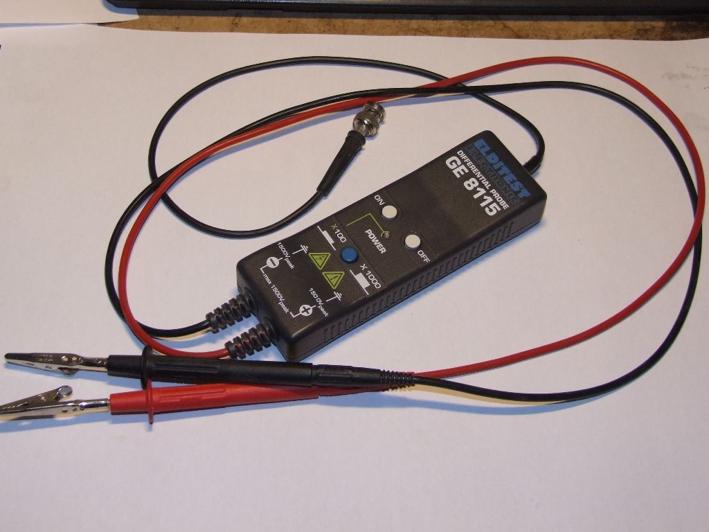
If I recall correctly differential probes have been discussed before, quite possibly wih SoD. This is what I use:
It's not isolated and doesn't need to be. However, it's not really the best probe for the measurement specified as it uses an input divide ratio of 100:1 or 1000:1. That's fine if you're measuring mains size voltages, but not helpful if one is trying to measure small voltages riding on a large common-mode voltage.
Andrew
10 May 2019 at 12:25 #408590 Robert Atkinson 2Participant@robertatkinson2
At CAT III 1000V and 80M input impedance that differential probe is effectively isolated and is ideal for the job in conjunction with a current clamp.
Croc clips are a bit dodgy though.
Robert G8RPI.
Edited By Robert Atkinson 2 on 10/05/2019 12:26:06
10 May 2019 at 14:12 #408614SillyOldDuffer
Moderator@sillyolddufferPosted by Robert Atkinson 2 on 09/05/2019 22:27:22:Posted by SillyOldDuffer on 09/05/2019 12:57:47:Posted by Andrew Johnston on 07/05/2019 11:17:00:Posted by SillyOldDuffer on 07/05/2019 10:36:40:I find it hard to get my head round what the effects of starting and loading a 3-phase motor powered by a VFD might be on current flowing on the input supply…
…
If you're going to do some measurements, and I'd be interested to see the results, you'd be better off (and safer) using a current transformer, like these:
…
Andrew
Thanks for the hint on current transformers – I shall order one.
…
Plan A looked like this:
This would allow the start-up current to be calculated accurately at any point of time over a few seconds, but setting up is slightly hairy because the measurements are taken at full mains voltage. Not frightened of that, but Andrew's 'current transformer' suggestion is both safer and likely to give indicative results with less fuss.
…
As shown your set-up is likely to damage your oscilloscope if it dosen't electrocute you. It will certainly trip any RCD you have on the circuit because you are connecting the neutral to ground via the oscilloscope.
As a minimum you need to use proper 600V CAT II high voltage 'scope probes and an isolation transformer. The proper way to do this is with isolated differential probe, a specialised oscilloscope with isolated inputs or a power analyser.It's really not something you should be playing around with unless you really need to and take precautions.
Robet G8RPI.
Robert, have you never used an oscilloscope on a hefty valve radio transmitter? My scope probes are suitable. The Gnd is the signal ground, and unless there is an earth fault, there is no difference between earth and neutral. Popping the RCD, or damaging the instrument, or electrocuting the operator whilst using an oscilloscope to measure mains voltage is a new one on me!
But as explained, Plan A isn't how I'm going to do it. Andrew suggested a current transformer, £4, which I've ordered. No need for an expensive differential probe, and no direct connection to the mains. The disadvantage of the current transformer method is it might not have the frequency response needed to catch spikes and it can't give accurate current measurements without me doing some sort of calibration. Nonetheless, I'm hoping the results will be sufficiently indicative. Unless EMC wrecks the experiment; the waveform close to the lathe could be dominated by VFD switching transients.
The question I'm exploring is: 'What current waveform is drawn from the single-phase supply by a VFD/3-phase motor combination when they are first switched on.'
I'm interested in the current profile over the first few seconds. With my lathe, I'm expecting to see a largish current, about 20A peak lasting a few hundred milliseconds, after which the current steadies down to a much lower level. Thereafter I expect the average current to be entirely proportional to the load on the 1.5kW motor, couple of amps idling, rising to 6 or 7A working hard.
Part of the fun is checking theory with an experiment. Double fun when the experiment itself is challenging.
Dave
10 May 2019 at 14:45 #408619Anonymous
Posted by SillyOldDuffer on 10/05/2019 14:12:01:
The disadvantage of the current transformer method is it might not have the frequency response needed to catch spikes and it can't give accurate current measurements without me doing some sort of calibration.
Current sensors are fairly good straight out of the box. You need a burden resistor on the secondary, usually tens or hundreds of ohms. The secondary has many turns, often 1000, and the primary one turn, ie, a wire through the hole in the middle. The manufacturer wil often give a formula for the voltage across a given resistor for a given primary current.
However, there's a caveat. Last year at work we had a need to measure a three phase supply, so we used three cheap, made in China, current transformers. The client complained about non-linearity at low currents. The transformers were rated at 20A and sure enough at less than 200mA or so they went non-linear. A lot of effort went into measuring the effect and correcting same in software. Then we bought exactly the same part (same company name and part number) but made in India. They were linear down to the limits of our measurements, a few milliamps. Go figure!
Andrew
10 May 2019 at 17:19 #408637john fletcher 1
Participant@johnfletcher1Years ago we used to indicate or measure Power Factor using a CRO on Single phase motors using a meter shunt in the Neutral, never injured or killed any one. If I remember correctly, one trace one trace across the shunt, the other across the supply. One hand in your pocket all the time.When carrying out such a thing one has to be of very careful and think what you are doing. We hadn't a small current transformer available to us, so used ones initiative which seem to be in short supply now days. John
PS I think the CRO was a Cossor
10 May 2019 at 18:36 #408644 Robert Atkinson 2Participant@robertatkinson2Posted by SillyOldDuffer on 10/05/2019 14:12:01:<SNIP>
Robert, have you never used an oscilloscope on a hefty valve radio transmitter? My scope probes are suitable. The Gnd is the signal ground, and unless there is an earth fault, there is no difference between earth and neutral. Popping the RCD, or damaging the instrument, or electrocuting the operator whilst using an oscilloscope to measure mains voltage is a new one on me!
But as explained, Plan A isn't how I'm going to do it. Andrew suggested a current transformer, £4, which I've ordered. No need for an expensive differential probe, and no direct connection to the mains. The disadvantage of the current transformer method is it might not have the frequency response needed to catch spikes and it can't give accurate current measurements without me doing some sort of calibration. Nonetheless, I'm hoping the results will be sufficiently indicative. Unless EMC wrecks the experiment; the waveform close to the lathe could be dominated by VFD switching transients.
The question I'm exploring is: 'What current waveform is drawn from the single-phase supply by a VFD/3-phase motor combination when they are first switched on.'
I'm interested in the current profile over the first few seconds. With my lathe, I'm expecting to see a largish current, about 20A peak lasting a few hundred milliseconds, after which the current steadies down to a much lower level. Thereafter I expect the average current to be entirely proportional to the load on the 1.5kW motor, couple of amps idling, rising to 6 or 7A working hard.
Part of the fun is checking theory with an experiment. Double fun when the experiment itself is challenging.
Dave
Hi Dave,
Yes I have looked at valve transmitters (2x4CX250) and similar with a 'scope. I use a Tektronix P6015 or HP 1137A EHT probe for that sort of work. For high energy e.g. connecting to mains, I use a Fluke ScopeMeter which has fully isolated inputs and properly rated, fully insulated probes. Using "normal" 'scope probes on mains is not immediately hazardous, but its certainly not safe. I've seen a scope lead go up in flames during this type of connection (no it wasn't me connecting it) The 'scope was destroyed by the current through the ground traces on the PCB. Connecting the 'scope common to neutral connects it to ground which will in almost all cases trip an RCD if fitted. The earth and neutral only need to be a few millivolts apart to drive the 30mA required to trip a typical RCD.You may be surprised by the current waveform you see at the input to the VFD on load. If it is a non power factor corrected drive you will see narrow high amplitude spikes, not a clean sinewave current. These current spikes are "topping up" the charge on the DC capacitor.
17 May 2019 at 18:32 #409679SillyOldDuffer
Moderator@sillyolddufferPosted by Andrew Johnston on 10/05/2019 14:45:19:Posted by SillyOldDuffer on 10/05/2019 14:12:01:
The disadvantage of the current transformer method is it might not have the frequency response needed to catch spikes and it can't give accurate current measurements without me doing some sort of calibration.
Current sensors are fairly good straight out of the box. You need a burden resistor on the secondary, usually tens or hundreds of ohms. The secondary has many turns, often 1000, and the primary one turn, ie, a wire through the hole in the middle. The manufacturer wil often give a formula for the voltage across a given resistor for a given primary current.
However, there's a caveat. Last year at work we had a need to measure a three phase supply, so we used three cheap, made in China, current transformers. The client complained about non-linearity at low currents. The transformers were rated at 20A and sure enough at less than 200mA or so they went non-linear. A lot of effort went into measuring the effect and correcting same in software. Then we bought exactly the same part (same company name and part number) but made in India. They were linear down to the limits of our measurements, a few milliamps. Go figure!
Andrew
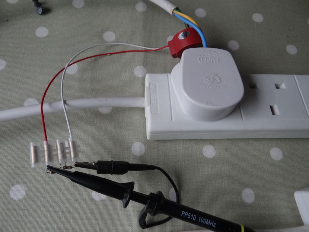
The current transformer arrived today and I was able to hook it up to an extension lead:
The live wire passes through a hole in the current transformer. There is no direct electrical connection to the mains.
I used a 60W tungsten bulb as a test load to prove I could:
- Measure the average current being fed to the lamp
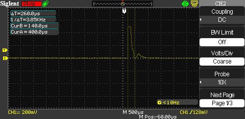
- Capture a switch-on spike.
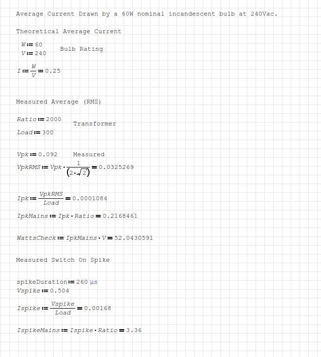
Success, although the transformer is non-linear at 60W, I got a reasonable match between theory (current calculated for a 60W lamp on 240Vac), and practice (current calculated from peak waveform measured with an oscilloscope and my – hopefully correct this time maths. Theory 0.25A, measured & calculated 0.22A.
The current transformer is a TA17 L-04. 2000:1 ratio, 0-20A converted to 0-10mA, 20Hz-20kHz, sample R 300Ω
After measuring the average, I tried to capture the switch on current surge. Another success.
Turning on a 60W tungsten filament bulb causes a 3.36A spike lasting about 260 microseconds. For average use a 1A fuse would be plenty for a 60W bulb drawing 0.25A. But the fuse would be stressed by that starting current, which is nearly 13.5 times higher normal. Fortunately, the spike doesn't last long.
In case I've fouled up the numbers, here's the sums. I calculated RMS current for normal running at 50Hz, and actual current for the spike, which doesn't repeat.
Busy weekend ahead but I hope to have time for some quick spike detecting on my VFD powered lathe on Sunday.
Dave
17 May 2019 at 18:59 #409682Carl Farrington
Participant@carlfarrington53722I'm pleased to have ignited some conversation
Thanks for your patience everyone on the whole 3 phase to single phase thing.
Now if somebody had just said that 3 phase datasheets always specified the current as per-phase, to begin with, I'd have saved everyone a lot of time

I should have my Churchill Cub hooked up soon and begin learning how to make things from metal.
20 May 2019 at 16:00 #410107SillyOldDuffer
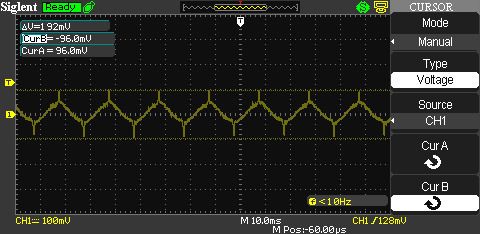
Moderator@sillyolddufferConnected my lathe to the oscilloscope with somewhat unexpected results.
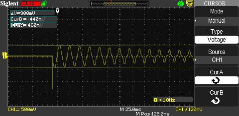
Firstly, there is only a short spike at power on, VFD only, the motor is switched off.

The spike is about 19A but it is very short. The current waveform immediately becomes a sine wave for several cycles over which the current gradually falls. Then short peaks, of about 0.6A, appear at the top of each cycle, although the waveform remains sinusoidal.
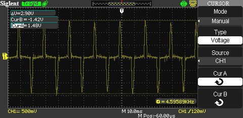
Switching the motor on makes the current peaks much larger. This is the motor running at 2500 rpm, with change gears, gearbox and drive shaft engaged, but the motor is otherwise unloaded.
This view show the current waveform to be dominated by sharp spikes, of about 9.6A each, and lasting about 2.4mS. As 50Hz UK mains takes 20mS to deliver a full cycle, the VFD only takes cuurent for about 10% of the available time. Presumably this is recharging the capacitors.
My VFD takes most current in sharp bursts at supply voltage peak. It does not spread demand for power across the supply waveform, nor does it soften the blow with any zero-crossing cleverness. The fuse is subjected to current spikes, not a gentle rise and fall. With the motor at 2500rpm the average current (measured with a wattmeter) is 3.1A but it is actually drawn from the mains in 9.6A pulses
Unfortunately I can't cut metal with the lathe and work the oscilloscope at the same time to see what a heavy load does to the current. Do the pulses get bigger or longer in duration or both? Don't know.
However, from the point of view of the 13A fuse:
- It has to survive a 19A pulse when the lathe is switched on.
- The fuse is subjected to a pulse load, not one smoothly proportional to mains voltage.
- When the lathe is consuming 3.1A on average it is actually taking power in 9.6A slices of about 2.4mS
- Unproven but, if the 3:1 peak to average is maintained, then the 6A average needed to drive a 1.5kW motor, is peaking at over 18A twice per cycle.
- Although the 13A fuse doesn't blow because it has time to cool, it must be stressed by this duty.
Going back to the original question, a 20A fast blow fuse looks like a better choice for 18A peaks than an ordinary 13A fuse. Although the 13A fuse might fail relatively early due to this mistreatment, it's not unsafe or unreliable. But pulse stressing an ordinary 13A fuse would be more problematical with a bigger motor, say 2.5kW: I think that's why the makers recommend high amperage fast blow fuses – a more appropriate balance of safety and reliability given all those sharp spikes.
My VFD is inexpensive. I suppose better electronics in a more sophisticated unit might load the mains less aggressively.
Dave
20 May 2019 at 16:04 #410108Carl Farrington
Participant@carlfarrington53722Hmm. Very interesting – great work Dave.
What are your thoughts on not using a fuse at all though, and using a 25A Type-B MCB instead?
20 May 2019 at 18:09 #410125 Mike PooleParticipant@mikepoole82104
It would be interesting to see how the charging waveform alters with the output frequency for the load
Mike
20 May 2019 at 18:26 #410128duncan webster 1
Participant@duncanwebster1I used to have an MCB in the supply to mine, more often than not it tripped when I switched the vfd on. On the advice of an electrical engineer I know I fitted a fuse (15A if I recall), no further trouble and it is several years ago. It is a proper distribution unit fuse, not the one in the plug. the workshop distribution box is fed from the main house box via a 30 A MCB (normal domestic type), this has never tripped due to workshop issues
20 May 2019 at 18:32 #410131SillyOldDuffer
Moderator@sillyolddufferPosted by Carl Farrington on 20/05/2019 16:04:56:Hmm. Very interesting – great work Dave.
What are your thoughts on not using a fuse at all though, and using a 25A Type-B MCB instead?
I don't know Carl, what I've done is mix owning an oscilloscope with basic electric theory. Being old fashioned I know a bit about fuses, but correct use of Circuit Breakers for this purpose takes me out of my depth. I'm pretty confident about fuses because they respond to heat. But I've no idea what effect that spiky waveform would have on the working of a circuit breaker. They could be ideally suited or the pulses might confuse them. Perhaps a real electrician can explain what the grown-ups do?
If it were me, being financially challenged, I wouldn't use the recommended fast blow fuse because of the cost. Instead I'd use an ordinary 13A fuse (safe and legal) and accept it might need to be replaced every so often. I think I can tell the difference between a fuse that pops infrequently for an expected reason, and a fuse that goes bang due to a fault.
Dave
20 May 2019 at 18:44 #410132SillyOldDuffer
Moderator@sillyolddufferPosted by Mike Poole on 20/05/2019 18:09:29:It would be interesting to see how the charging waveform alters with the output frequency for the load
Mike
Wish you'd suggested that earlier Mike – I need another current transformer to test VFD output frequency as well as input current. Never occurred to me to buy two.
Although I'm sure I've looked at the VFD output waveform before. Can't remember how I did it – certainly not a direct connection. As I recall each phase looks roughly like 50Hz overall but the sinusoid is built up from hundreds of fast pulses about 10kHz – I'm sure I wrote it down, but where's the notebook?
Dave
20 May 2019 at 19:56 #410141Anonymous
Bleep, bleep, bleep I just lost what I typed. Mumble, mumble &*@# forum software.

Let's try again, but I'll miss out some of the detailed explanations in case I lose the **** lot again. I can always expand on a given topic at a later date if needed.
————————————–
First I think we owe a vote of thanks to SoD for making these measurements. Darn it, should we ever meet I'd even buy him a beer.

The current measurements are pretty much what I would expect. The initial short spike is probably some EMC/filter capacitors charging. Looking at the current waveform after that it is not sinusoidal as stated by SoD. If one looks closely the first cycle or so is sine like, but after that each half cycle pulse becomes slightly narrower with a longer period of no current flow between peaks. Exactly what one would expect for a rectifier charging a bank of capacitors starting from full discharge.
With the motor running the current waveform is as expected. Even on no load the motor consumes some power, so the DC link voltage will decease as current is drawn by the motor. The rectifier can only charge the DC link capacitors when the input voltage is greater than the DC link voltage. This only happens near the top of the input voltage waveform. Hence the short current pulses. If an input voltage waveform was superimposed on the current waveform they would nearly coincide, with the current pulse beginning somewhat before peak voltage and ending at, or slightly after, peak voltage.
While it would be interesting to make measurements of the input current with the motor under load we can predict what the current waveform will be. More current will be drawn by the motor so the DC link voltage will drop further on each cycle. So the input current will start flowing earlier in the input voltage cycle. The current pulse will get wider, with the rising edge starting earlier and the trailing edge staying pretty much where it is.
From an electricity generators point of view the input current spikes are bad. That's why most VFD manuals recommend the use of an input filter. As well as preventing high frequency noise from entering the mains they also smooth out the current pulses so the VFD looks more like a resistive load, thus reducing the current harmonics on the mains.
Larger and/or more expensive VFDs may have a power factor corrector at the front end. This replaces the simple rectifier and is essentially a rectifier followed by boost converter that controls input current to keep it proportional to input voltage, in which case the input current will be sinusoidal.
To save SoD looking for his notes the output waveforms, from each phase to neutral, will be a PWM waveform swinging between the DC link voltage and neutral. The base PWM frequency is normally in the range 4-16kHz and the width of the PWM pulses changes every cycle so that the fundamental of the PWM waveform is a sine wave of whatever frequency is desired and with the appropriate phase shift.
Andrew
20 May 2019 at 21:31 #410157 Robert Atkinson 2Participant@robertatkinson2
Andrew has explained this perfectly. I do note that SoD's calculations look bit suspect. For starters it's normal to use peak to peak rather than peak. More importantly, the root two factor only applies to pure sinewaves.
The 13 amp fuse will not be stressed at all by 18A at a couple of milliseconds. The main effect is thermal and this will be averaged by the mass of the wire and the sand packed around it. In fact a 13A BS1362 fuse will not blow when passing 20A (RMS or DC) for long periods of time (hours). It will take 100A for 10ms without blowing.So a 13A plug fuse will not blow under this load and a 5A one would probably be a better choice as it will actually blow under sustained load. You might get failures if you try to start the motor under load though. An MCB needs to be higher current rating or/and B orC type as they operate on magnetic attraction so are much more sensitive to pulse currents.
Edit: found a good explanation of 13A fuse rating https://www.pat-testing-training.net/articles/fuse-operation-characteristics.php
Robert G8RPI.
Edited By Robert Atkinson 2 on 20/05/2019 21:31:45
Edited By Robert Atkinson 2 on 20/05/2019 21:32:58
21 May 2019 at 11:26 #410219SillyOldDuffer
Moderator@sillyolddufferThanks Andrew – that's a very helpful explanation and development of the results. I have a filter tucked away to reduce RFI from the VFD: I ought to fit it and see how much it improves the supply-side waveform.
Also, thanks to Robert for the link to the graph of BS1362 fuse characteristics. The shape of the current vs time characteristic is more or less what I expected, that it lies above the 20A line wasn't!
The point about my dubious maths is well made too: I often issue health warnings and show working so it can be checked. It's because I either:
- Get both theory and calculation wrong, or
- The calculation is right but the theory is wrong, or
- The theory is right but the calculation is wrong, or – happy days –
- Both theory and calculation are right at the same time. Statistically I should be right 25% of the time. Doesn't often work out that way – once in a blue moon…
Dave
-
AuthorPosts
- Please log in to reply to this topic. Registering is free and easy using the links on the menu at the top of this page.
Latest Replies
Home › Forums › General Questions › Topics
-
- Topic
- Voices
- Posts
- Last Post
-
-
Warco Super Major Milling Machine – Stripping Gearbox
Started by:
Lee Jones 6 in: Manual machine tools
- 8
- 12
-
29 August 2025 at 07:15
jacobsmess
-
Indicator bulb with bayonet mount needed
Started by:
Wade Beatty in: Electronics in the Workshop
- 6
- 6
-
29 August 2025 at 07:05
 Robert Atkinson 2
-
125 mm chuck onto my lathe
Started by:
 Steve Huckins
in: General Questions
- 7
- 9
-
29 August 2025 at 06:46
 JasonB
-
interchangeable Myford beds
Started by:
Kundrus in: Manual machine tools
- 3
- 3
-
29 August 2025 at 01:44
DMR
-
Mercer comparator gauge repair help.
Started by:
Graeme Seed in: Workshop Tools and Tooling
- 4
- 7
-
28 August 2025 at 23:13
 Michael Gilligan
-
Painting mating surfaces
Started by:
Martin Cooper in: Beginners questions
- 9
- 17
-
28 August 2025 at 22:46
 Bazyle
-
Smart & Brown Model L lathe help required
Started by:
AJAX in: Manual machine tools
- 4
- 13
-
28 August 2025 at 20:50
AJAX
-
Progress no.1 restoration
Started by:
flyingsailor in: Workshop Tools and Tooling
- 9
- 13
-
28 August 2025 at 20:31
old mart
-
boiler leak
Started by:
Bill Dawes in: Locomotives
- 12
- 24
-
28 August 2025 at 19:07
Bill Dawes
-
Bendy Flexible Plywood
Started by:
Henry Buckeldee in: Related Hobbies including Vehicle Restoration
- 14
- 16
-
28 August 2025 at 18:13
Henry Buckeldee
-
Lathe tool inserts
Started by:
Andy Brocklehurst in: Beginners questions
- 9
- 20
-
28 August 2025 at 18:08
Diogenes
-
Museum donation
Started by:
Stephen Wessel 1 in: Introduce Yourself – New members start here!
- 4
- 6
-
28 August 2025 at 16:18
Stephen Wessel 1
-
Damp engine, Name?
Started by:
sivtek1 in: Stationary engines
- 6
- 14
-
28 August 2025 at 13:58
 cogdobbler
-
Phone Phreaking
Started by:
 Michael Gilligan
in: Clocks and Scientific Instruments
- 13
- 17
-
28 August 2025 at 08:13
Roger Hart
-
What Did You Do Today 2025
1
2
…
9
10
Started by:
 JasonB
in: The Tea Room
- 36
- 231
-
28 August 2025 at 00:07
howardb
-
Granville lathe leadscrew change wheel
1
2
Started by:
JACK SIDEBOTHAM in: Help and Assistance! (Offered or Wanted)
- 13
- 31
-
27 August 2025 at 21:06
Howard Lewis
-
Weird electric actuator action
Started by:
ell81 in: Beginners questions
- 5
- 5
-
27 August 2025 at 17:42
 Robert Atkinson 2
-
Marcus Oxen … illustrated notebook
Started by:
 Michael Gilligan
in: The Tea Room
- 2
- 2
-
27 August 2025 at 16:45
 Harry Wilkes
-
Softening epoxy
1
2
Started by:
John Haine in: General Questions
- 21
- 38
-
27 August 2025 at 12:56
 Robert Atkinson 2
-
Hereward
Started by:
 Richard Simpson
in: Model Boats
- 6
- 11
-
27 August 2025 at 11:06
 cogdobbler
-
Imperial Bearing Surprise!
Started by:
Peter_H in: General Questions
- 4
- 4
-
27 August 2025 at 10:06
tonychap
-
QCTP for chester lathe
1
2
Started by:
Chris12 in: Beginners questions
- 12
- 32
-
27 August 2025 at 08:17
 Vic
Vic
-
Bending copper tube?
Started by:
Bo’sun in: Workshop Techniques
- 13
- 16
-
27 August 2025 at 02:05
 cogdobbler
-
The skill of the Victorian woodcut engraver
Started by:
 vic newey
in: The Tea Room
- 5
- 6
-
26 August 2025 at 22:12
SillyOldDuffer
-
Myford VMB mill, head lift.
Started by:
lctikka61 in: Manual machine tools
- 3
- 3
-
26 August 2025 at 20:41
Alan Wood 4
-
Warco Super Major Milling Machine – Stripping Gearbox
-
Latest Issue
Newsletter Sign-up
Latest Replies
- Warco Super Major Milling Machine – Stripping Gearbox
- Indicator bulb with bayonet mount needed
- 125 mm chuck onto my lathe
- interchangeable Myford beds
- Mercer comparator gauge repair help.
- Painting mating surfaces
- Smart & Brown Model L lathe help required
- Progress no.1 restoration
- boiler leak
- Bendy Flexible Plywood


