Interpreting drawing?

Advert

Interpreting drawing?

Home Forums Beginners questions Interpreting drawing?

Viewing 25 posts - 1 through 25 (of 33 total)
  • Author
    Posts
  • #78925
    Cornish Jack
    Participant
      @cornishjack

      G’day all.
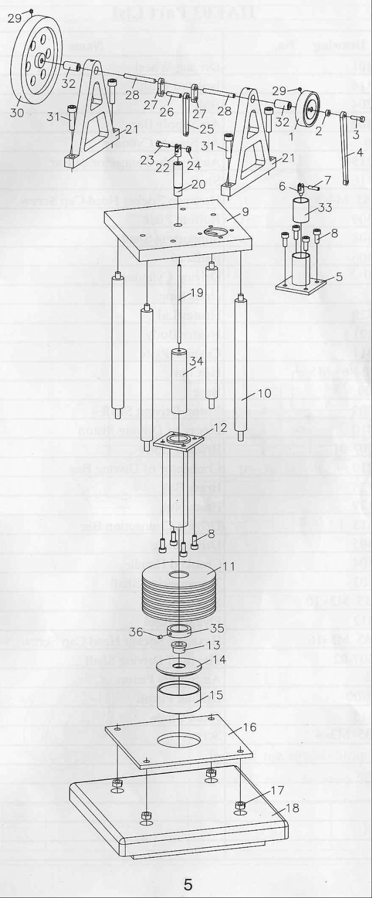
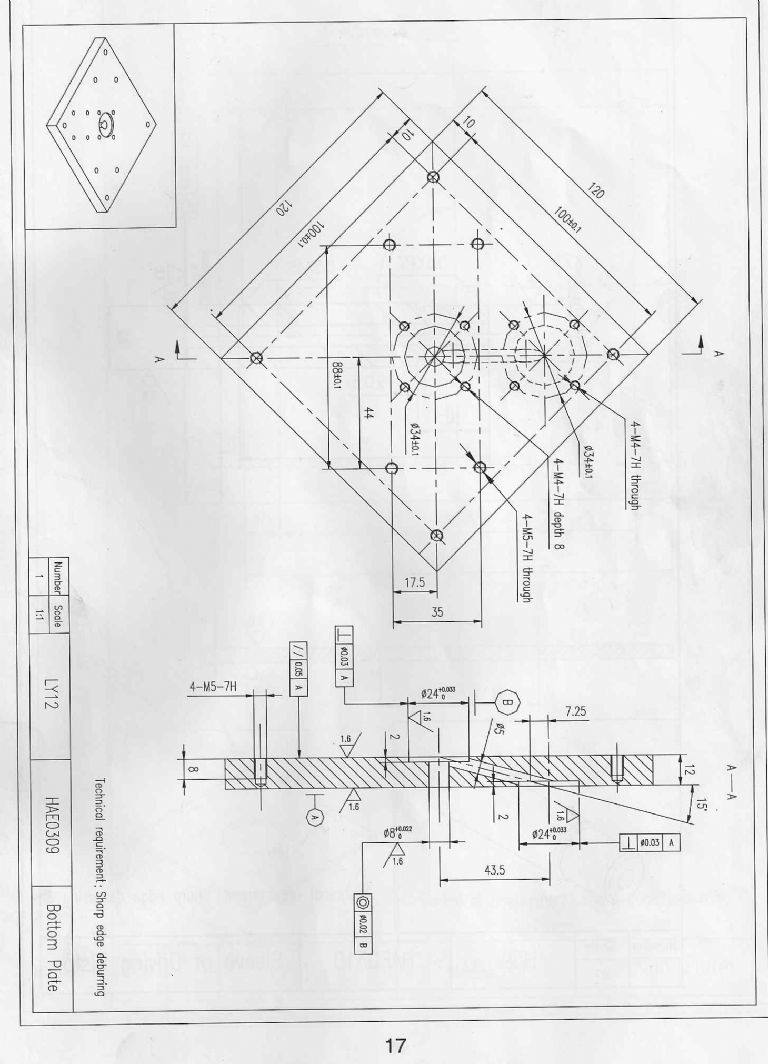
      The above drawings are for a Sieg hot air engine which I’m in the process of mangling. There are very few written instructions and they are in ‘Chinglish’. I am having difficulty getting my head around the machining of the plate in the second piccy – I think it is inverted … the sloping transfer passage I would have expected to upwards from the hot end to the right to the cold end. Could someone with drawing reading skills please check and confirm, please?
      TIA
      Rgds
      Bill
      Advert
      #5780
      Cornish Jack
      Participant
        @cornishjack
        #78927
        Les Jones 1
        Participant
          @lesjones1
          Hi Bill,
          I think you are assuming that the plate edge view at the bottom of the page is the
          the correct way up. If you look at the blind holes that the pillars screw into you can see that face must be at the bottom. I think this is to do with first angle / third angle projection.
          (I can never remember which is which.)
           
          Les.
          #78928
          JasonB
          Moderator
            @jasonb
            The main problem is that both the 24mm recesses are shown on the opposite side by the use of hidden detail but the section shows them correctly with one each side.
             
            EDIT just blew it up larger the central hole is nor shown with dotted lines so the drawing is correct but shows the underside.
             
            Going by the general assembly drawing it looks like the passage should go upwards from the central recess to the off set one on the top surface. So as you look at the section the bottom of the plate is on the left.
             
            The small Isometric view is of the underside going by the blind holes in teh corners
             
            J

            Edited By JasonB on 30/11/2011 16:53:17

            #78931
            Terryd
            Participant
              @terryd72465
              Hi Bill,
               
              The second drawing you refer to appears to be in third angle projection rather than the now preferred first angle. The central counterbore with the through hole is in fact the underside of the plate, which I assume to be the hot end (I know very little about Hot air engines) and the transfer port indeed slopes upwards to the second counterbore which is on the top according to the exploded assembly diagram at the top of yor message.
               
              So if the drawing was in the proper orientation, i.e. landscape, the top of the plate on the sectioned view (to the right) is in fact the right hand side. I hope that makes sense having re read it it seems confusing. PM me if you have a problem with interpreting it and I will try to help.
               
              Regards
               
              Terry
              #78934
              Cornish Jack
              Participant
                @cornishjack
                Wow!!!
                Thank you Les, Jason and Terry – just popped off for a cuppa and come back to my question sorted. For a simpleton like me, the plate diagram is upside-down … yes?
                Rgds
                Bill
                #78935
                Les Jones 1
                Participant
                  @lesjones1
                  Hi Bill,
                  I’ve just noticed that the drawing has been rotated clockwise by 90 deg. If it was viewed with the left hand edge as the bottom it would not be quite as confusing.
                   
                  Les.
                  #78937
                  The Merry Miller
                  Participant
                    @themerrymiller
                    Nice to see a bit of geometric tolerancing for a change!!
                     
                    Len. P.
                     
                     
                    #78939
                    Clive Hartland
                    Participant
                      @clivehartland94829
                      The exploded view shows the plate in its correct orientation with the offset hole in the upper face. ergo, the drawing is in fact upside down and the cross section shows the hidden detail with the sloping hole downwards towards the central hole.
                      The Isometric drawing shows the under face view.
                      This is not 1st angle nor 3rd angle but just a detail drawing with a cross section.
                      This is nearly always included as a seperate sheet or a boxed drawing on the main drawing.
                       
                      clive
                      #78955
                      Terryd
                      Participant
                        @terryd72465
                        Sorry Clive but it is third angle. It has to be one or the other, it certainly isn’t 2nd or 4th. Just because there ar only 2 views does not change that fact.
                         
                        Regards
                         
                        T
                        #78957
                        Cornish Jack
                        Participant
                          @cornishjack

                           
                          Anyone remember Harry Hemsley? I am starting to feel like him when he used to produce his catch-phrase. “What did Horace say, Winnie?” I can cope with upside-down but nil comprende 2nd angle, 3rd angle etc!!
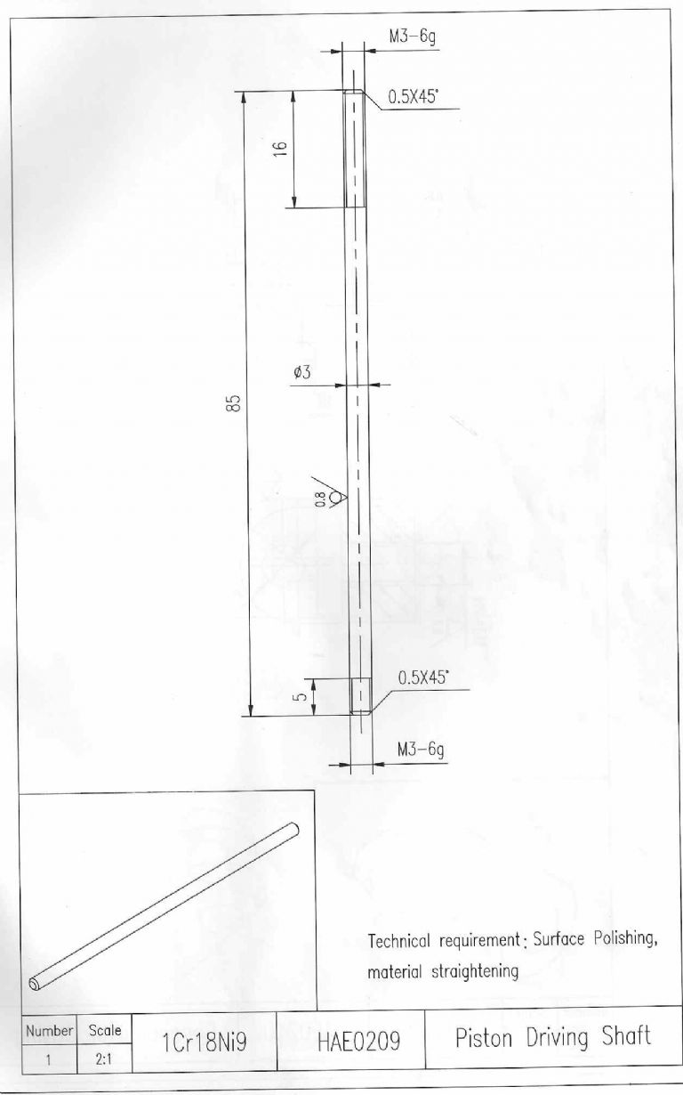
                          However, to strike while there are lots of knowledgeable folk about. …the new piccy is yet another that I ‘see’ as being upside-down. It is item 19 in the exploded view and connects the hot piston to the little end yoke. As I read it, it is threaded 3mm for 5mm at one end and 16mm at the other. However, the illustrated orientation puts the 16mm length at the ‘top’ (where the little end yoke is) and the 5mm at the bottom to connect to the piston. In point of fact, I don’t have metric taps/dies so made an ‘executive decision’ to modify it to 6 BA. All well and good but I am using the 16mm length at the piston end. One supposes that such a relatively long thread is there for adjustment purposes but I have no idea what that adjustment should be and the booklet says nowt!
                          All suggestions gratefully received.
                          TIA
                          Rgds
                          Bill
                          #78974
                          Terryd
                          Participant
                            @terryd72465
                            Posted by Cornish Jack on 30/11/2011 21:53:32:

                            ………………. In point of fact, I don’t have metric taps/dies so made an ‘executive decision’ to modify it to 6 BA. All well and good but I am using the 16mm length at the piston end. …………….
                             
                            TIA
                            Rgds
                            Bill
                            Hi Bill,
                             
                            You may not have ISO metric taps but you do have metric ones. BA threads are in fact based on metric dimensions, not imperial.
                             
                            Regards
                             
                            ElTel

                            Edited By Terryd on 01/12/2011 05:54:16

                            #78978
                            S.D.L.
                            Participant
                              @s-d-l
                              Posted by Cornish Jack on 30/11/2011 21:53:32:

                               
                              Anyone remember Harry Hemsley? I am starting to feel like him when he used to produce his catch-phrase. “What did Horace say, Winnie?” I can cope with upside-down but nil comprende 2nd angle, 3rd angle etc!!
                              However, to strike while there are lots of knowledgeable folk about. …the new piccy is yet another that I ‘see’ as being upside-down. It is item 19 in the exploded view and connects the hot piston to the little end yoke.

                              TIA
                              Rgds
                              Bill
                              Detail drawings such as the shaft are often not drawn in the same orientation as the assembly drawings. They are often rotated to fit the paper orientation portrait / landscape etc or so that a certain face is easier to detail or see.
                               
                              I would guess long thread down with a nut used as a lock-nut.
                               
                              Steve Larner
                              #78983
                              Ian S C
                              Participant
                                @iansc
                                ! would agree with long thread into the displacer, but I would tend to leave the locknut off, get the length, if too much surplus cut it off, then reassemble with loctite (just screw lock), I like to get rid of as much weight as I can. My latest motor has a 2.5 mm displacer shaft, with a 6 BA thread on the displacer end, and a clamp type fitting on the gudgeon fork end. Ian S C
                                #78992
                                Cornish Jack
                                Participant
                                  @cornishjack
                                  Thank you Terry, Steve and Ian.
                                  Ian – “get the length” – thereby lies the problem. How does one gauge the correct length? I’m assuming that the most basic mode would be to ensure that the displacer (that’s the word!!) mustn’t contact either end of the cylinder, but how much clearance? Is there some sort of formula for calculating this to enhance performance or is it strictly ‘suck it and see’? Is it just a matter of cylinder length minus crank throw divided by 2? So many questions, so little knowledge (that’s me, of course!!)
                                  Rgds
                                  Bill
                                  #78997
                                  Ian S C
                                  Participant
                                    @iansc
                                    Bill, I don’t bother with maths, I measure the length of the cylinder, and the length of the displacer plus stroke, the extra length of the cylinder divide by two, find a washer, bit of cardboard, or something,drop it down the hole and assemble the displacer assembly, put the forks on the rod and hook up the con rod, You should be able to turn the motor over with it just touching the spacer at the bottom. Take the cylinder off, and take the spacer out NOW, it won’t hurt if the bottom end has a few thou bigger gap than the cold end, thats where the expansion takes place.
                                     
                                    The motor I just finished is similar to the SIEG, and GRIZZLY horizontal beam motor, it has a bore of 3/8″, and a stroke of 1/2″, The displacer cylinder is made from the steel case of a AA size NiCad battery, no plans so all mistakes are mine–wot mistakes! I really need a non contact tacho, my geared on is OK on the bigger motors, but it takes too much power with the little ones, my guess is about 2500rpm, maybe nearer 3000, its just been a bit of a design difficulty making a small enough burner. Ian S C
                                    #79020
                                    Cornish Jack
                                    Participant
                                      @cornishjack
                                      Thank you Ian. Just the info I was after. That washer/cardboard spacer idea is ideal. If I manage to complete this your help will have been invaluable. I suspect that it will be many years before I could work at the sizes of your latest.
                                      Rgds
                                      Bill
                                      #79049
                                      Ian S C
                                      Participant
                                        @iansc
                                        Hi Bill, I don’t think I;ll be working to that scale again (never say never).
                                        Spent the day in Christchurch today, and visited one of the hobby shops, where I hade discovered a few months ago they had a little hot air engine kit (German I think), so today I had a good look at it, then went to the counter and asked the staff if they had got it to work, the bloke who assembled it said no, but we tried for 2 hours. I then showed them why, Its a GAMMA with parallel cylinders, and they had both displacer and piston moving together, instead of being 90* apart, we did’nt try it, but next time I’m in town I must go and see how they get on. Its got about 12 mm bore and 6 mm stroke, so it should go like one thing. Might take one of my motors in so they can see that Stirling engines do work. Ian S C
                                        #79216
                                        Sub Mandrel
                                        Participant
                                          @submandrel
                                          > both displacer and piston moving together, instead of being 90* apart,
                                          On holiday in France many years ago, i bought a model boat magazine (I was able to read it too!) There was an article and plan for a two-cylinder single acting steam engine with the cranks at 90 degrees. Think about it…
                                          Neil
                                          #79248
                                          Ian S C
                                          Participant
                                            @iansc
                                            I made a V twin single acting wobbler (very basic design), 1/4″ bore x 1/2″ stroke to power a boat about 17″ long, The boat has since been extended to 26″, and been fitted with a hot air engine. Ian S C
                                            #79249
                                            Cornish Jack
                                            Participant
                                              @cornishjack
                                              G’day again. Yet another question.
                                              I’ve had a few “Good Lord, that was lucky” moments in machining the Sieg and have now reached the stage of needing to drill the acutely angled transfer passage between the hot and cold ends. It is shown in the second drawing and extends at an angle of 15degs from a point 4mm from the outside edge of the ‘blind’ cold end boring to emerge in the hot end bore. Final drill size is 5mm. The angle is making my head hurt!! I think I may have a ‘cunning plan’ but would appreciate any comments/advice.
                                              Intention is to turn down a piece of bar to a diam of 23.96mm (the blind bore diameter and offset that at 15 degs and drill through at, say, 3.5 mm, at a point 4mm in from the periphery. I would part that off and clamp it in situ in the blind bore and use it as a guide for the same sized drill through the plate.
                                              First question – is this practical?
                                              2nd Q = the plate is designed at 12mm thick but having got it reasonably flat at 13.2mm and the two bores about right dimensions, I am reluctant to do any more machining to size, so the transfer passage exit will not be quite as per ‘spec’ – does this matter?
                                              Responses, pro or con would be welcomed.
                                              TIA
                                              Rgds
                                              Bill
                                              #79301
                                              Ian S C
                                              Participant
                                                @iansc
                                                Bill, the thickness of the plate does not matter too much, if it was me a good bit of metal underneath the plate would be removed, so that except around the cylinders, and a narrow strip around the edge, the rest of the plate would be about 3 mm thick, same sort of treatment on the base if made of metal as most of mine are.
                                                The hole does not have to be all that accurate, as long as it goes from one cylinder to the other. On two of my motors the communicating hole is horrizontal, 5 mm dia, and the drill ended up being gripped by the last 5 mm of the shank, and the hole went right up to the chuck. The outside end was plugged. A better design for the motor you are building is to over lap the two cylinders, the counter bores for the cylinder meets, and theres the hole,looks like this (). Ian S C
                                                #79305
                                                Cornish Jack
                                                Participant
                                                  @cornishjack
                                                  Thank you Ian, particularly for the reassurance on the transfer hole. I’ve made the drill guide – nice bit of cast iron, turned and drilled beautifully. Now comes the acid test getting it all lined up and drilling the plate. I won’t modify the plate, mainly ‘cos the only example of this I’ve seen seems to have stayed with the original dimensions. Will let you know how it turns out
                                                  Rgds
                                                  Bill
                                                  #79321
                                                  Robert Dodds
                                                  Participant
                                                    @robertdodds43397
                                                    Jack,
                                                    If you are still in doubt about 1st and 3rd angle projection take a look at Wikipedia
                                                    ” Multiview Orthographic Projection”
                                                    I still think the US / French Cotton Spool convention for 1st and 3rd is the simplest to grasp.
                                                    Bob D

                                                    #79323
                                                    Terryd
                                                    Participant
                                                      @terryd72465
                                                      Hi Robert,
                                                       
                                                      The truncated cone symbol indicating projection view is a standard used in this country as well. I taught engineering graphics from the mid 1970s and we used it then as a standard means of indicating the angle of projection used. It is indeed a very useful, simple and universally understood method of distinguishing views.
                                                       
                                                      Best regards
                                                       
                                                      Terry
                                                       
                                                      Terry
                                                    Viewing 25 posts - 1 through 25 (of 33 total)
                                                    • Please log in to reply to this topic. Registering is free and easy using the links on the menu at the top of this page.

                                                    Advert

                                                    Latest Replies

                                                    Home Forums Beginners questions Topics

                                                    Viewing 25 topics - 1 through 25 (of 25 total)
                                                    Viewing 25 topics - 1 through 25 (of 25 total)

                                                    View full reply list.

                                                    Advert

                                                    Newsletter Sign-up