INT30 sensitive drilling attachment

Advert

INT30 sensitive drilling attachment

Home Forums Manual machine tools INT30 sensitive drilling attachment

Viewing 17 posts - 1 through 17 (of 17 total)
  • Author
    Posts
  • #435367
    Mark Davison 1
    Participant
      @markdavison1

      I've just bought a Harrison vertical mill with INT30 spindle (although not yet collected it).

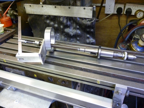
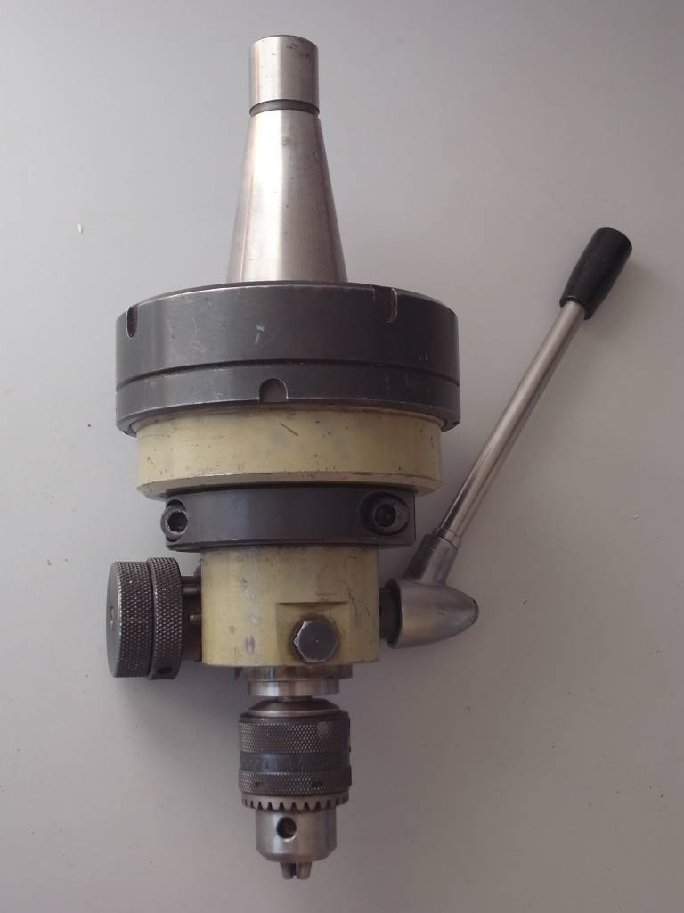
      I bought this despite being reluctant to buy a mill without a quill, primarily as I don't have the height for a Bridgeport type machine. I want to be able to do some drilling on the machine and stumbled across this on **LINK**

      I'm looking to make something like this but using a straight shank ER collect chuck inserted directly into an INT30 to MT3 adapter (such as the one below – 87mm long extension) that has had the morse taper bored out to a parallel 25mm hole. What are my chances of boring out this supposedly hardened INT30 adapter with carbide tooling and getting a satisfactory surface finish? Or should I sleeve after boring, say with brass, and then bore that?

      Advert
      #13683
      Mark Davison 1
      Participant
        @markdavison1
        #435375
        Emgee
        Participant
          @emgee

          Hi Mark

          Good idea to save cranking the knee to drill but with a 1/2" drawbolt doesn't give much material for the operating shaft, could be in danger of the chuck part going AWOL.

          An alternative solution would be to motorise the knee with a stepper and simple controller.

          Emgee

          #435380
          IanT
          Participant
            @iant

            I have the same lack of 'quill drilling' problem on my horizontals Mark.

            The Victoria has a MT3 vertical head and my thinking is that I will drill (and lap) a hole in a MT3 blank arbor to take an ER16 collet chuck (with straight 12mm shank) and basically build a larger version of the ArcEuro Trade sensitive drilling adaptor. The down feed will probably be via a lever under the head though (not acting through the spindle) – so no problems with the drawbar. I'll mill a slot in the MT3 bit and place a drive pin in the ER16 shank. Might have to slim the back of the chuck head to take a smaller bearing – or come up with a revolving pressure plate behind it to bear down on. The ER16 collet will hold drills up to 10mm – larger than I actually need generally.

            You could do the same with the INT30/MT3 adaptor – and use the outside of this to hold the down-feed lever mech. Same general idea but an easier approach I think – blank arbors not being hardened and they cost a bit less if you screw it up (which of course I'm sure you won't ).

            Anyway – that's what it says under "Quills" on my TUIT list….

            Regards,

            IanT

            #435420
            DC31k
            Participant
              @dc31k

              Have a look at how Schaublin do their sensitive drilling attachment for the 30 taper spindle on the 13 mill.

              It locates on the spindle nose itself, like a big facemill would.

              Much easier to make than something that locates in the taper.

              You need to think of how the drive will be transmitted while still allowing sliding movement. Generally done with a key and keyway. A dog point grub screw into the 3MT adaptor could be used, but requires tapping a hard part. An accurate keyway is equally difficult in a hardened ER straight shank chuck.

              Copying the Schaublin design would allow you to put keyway in unhardened spindle nose adapter and use angle grinder to form a not-very-precise-over-wide slot in ER chuck and then JB Weld in a key (using the adapter to keep it aligned while it sets).

              See bottom left of page 6 here:

              https://drive.google.com/file/d/0Bxr59DtuJda_amx1V1dvNE8xVXM/view?usp=sharing (Anglo-Swiss Tools, Schaublin 13, French catalogue)

              for nose dimensions. Top right of page 12 for attachment complete.

              I have a drawing for all the Schaublin parts so if you PM me with contact details, I can send to you.

              #435572
              old mart
              Participant
                @oldmart

                Just a thought, but these boring heads are screwed onto the arbor, and if you have a lathe, you would have more options to design the keyed sliding part, and also have a boring head at the same time.https://www.ebay.co.uk/itm/SOBA-50-mm-Boring-Head-Complete-with-Tools-INT-30-Shank-Metric-17113030-ISO30/372164615910?epid=3011275466&hash=item56a6bd5ee6:g:kRIAAOSwDFBaL9SP

                An er32 collet holder also has a thread which has potential.

                Edited By old mart on 01/11/2019 19:47:58

                Edited By old mart on 01/11/2019 19:50:51

                #435588
                Mark Davison 1
                Participant
                  @markdavison1

                  Thanks for the suggestions. I was hoping to use at least some of the depth of the INT30 taper so as not to loose too much of the available height. Once I collect it next week I'll see how important that is. I have a lathe and a MT3 boring head so will need to buy an INT30 one anyway.

                  #435596
                  old mart
                  Participant
                    @oldmart

                    Its a difficult project, what with the core diameter of the pull stud being only 9.85mm and some method to allow the chuck shaft to move axially and turn with the toolholder via a keyway or similar. The stroke will be severely limited, if the whole assembly is not fairly long.

                    These sidelock spindles may have the answer to the finish of the bore and the screws could drive a slotted spindle.

                    **LINK**

                    #435627
                    DC31k
                    Participant
                      @dc31k
                      Posted by Mark Davison 1 on 01/11/2019 20:35:05:

                      I was hoping to use at least some of the depth of the INT30 taper so as not to loose too much of the available height.

                      Using a spindle nose cap, it can project upwards into the taper to give the height and length for support, but does not need to be machined to fit the taper.

                      #435630
                      DC31k
                      Participant
                        @dc31k
                        Posted by old mart on 01/11/2019 21:14:15:

                        Its a difficult project, what with the core diameter of the pull stud being only 9.85mm and some method to allow the chuck shaft to move axially and turn with the toolholder via a keyway or similar. The stroke will be severely limited, if the whole assembly is not fairly long.

                        These sidelock spindles may have the answer to the finish of the bore and the screws could drive a slotted spindle.

                        **LINK**

                        The sidelock holders do project downwards so a bit of headroom is lost.

                        Your idea of a boring head shank is very good. They are unlikely to be through hardened and a nose cap could be used to hold it into the spindle, thus eliminating the troublesome drawbar. Think Myford spindle nose MT2 collets. Cut the top off it as necessary as the full length of the taper is not needed for axial drilling loads.

                        You could use the threads originally destined for the boring head to screw on an unhardened piece that provides the sliding drive system.

                        Was is Erikson who did a quickchange toolholding system for Bridgeports that used a cap to retain the tooling instead of a drawbar?

                        In practice, stroke length is limited by lever ratio at the top end. 6:1 ratio, for instance needs lever to go 300mm for 50mm quill travel.

                        Edited By DC31k on 02/11/2019 08:48:51

                        #435701
                        old mart
                        Participant
                          @oldmart

                          The quill will need 1 1/2" overlap when in the extended position, and this is added to whatever travel it has. This is why I thought one of those sidelock holders might be suitable. Of course, the seller does not include the length of the bore of any of them, so its pot luck.

                          #435853
                          Mark Davison 1
                          Participant
                            @markdavison1
                            #435864
                            old mart
                            Participant
                              @oldmart

                              Shame its a 40 size, I wonder how it is prevented from spinning round if you let go of the handle?

                              It would be too long even if it was a 30 fitting.

                              #435874
                              old mart
                              Participant
                                @oldmart

                                I have just found out that Gloucester tooling sell the iso30 boring head shank on its own. The thread is 1 1/2 X 18. They may be hard to drill and bore, but the thread would come in useful, as you might add more than one different length of extension to the shank for different quill travel requirements with bores matched. 

                                Edited By old mart on 03/11/2019 20:52:03

                                #436503
                                Mark Davison 1
                                Participant
                                  @markdavison1
                                  Posted by DC31k on 31/10/2019 16:42:49:

                                  Have a look at how Schaublin do their sensitive drilling attachment for the 30 taper spindle on the 13 mill.

                                  It locates on the spindle nose itself, like a big facemill would.

                                  Much easier to make than something that locates in the taper.

                                  You need to think of how the drive will be transmitted while still allowing sliding movement. Generally done with a key and keyway. A dog point grub screw into the 3MT adaptor could be used, but requires tapping a hard part. An accurate keyway is equally difficult in a hardened ER straight shank chuck.

                                  Copying the Schaublin design would allow you to put keyway in unhardened spindle nose adapter and use angle grinder to form a not-very-precise-over-wide slot in ER chuck and then JB Weld in a key (using the adapter to keep it aligned while it sets).

                                  See bottom left of page 6 here:

                                  https://drive.google.com/file/d/0Bxr59DtuJda_amx1V1dvNE8xVXM/view?usp=sharing (Anglo-Swiss Tools, Schaublin 13, French catalogue)

                                  for nose dimensions. Top right of page 12 for attachment complete.

                                  I have a drawing for all the Schaublin parts so if you PM me with contact details, I can send to you.

                                  I've finally got my head round what you meant when you said mount directly to the spindle nose. I still haven't got the mill (long story involving haulage company) so hadn't realised there are 4 threaded holes in the nose. The bit I still cant picture, even after study the drawing you sent (thankyou) is which way up the adapter mounts to the nose. I'd have assumed the ground face mates with the nose but the assembly drawing suggests it goes the other way, with he ground face down?

                                  #436535
                                  DC31k
                                  Participant
                                    @dc31k
                                    Posted by Mark Davison 1 on 09/11/2019 09:38:15:

                                    The bit I still cant picture, even after study the drawing you sent (thankyou) is which way up the adapter mounts to the nose. I'd have assumed the ground face mates with the nose but the assembly drawing suggests it goes the other way, with he ground face down?

                                    Sorry, I thought I had added a note on the email. The assembly drawing is incorrect, my fault. The ground part is up, the counterbored holes are down.

                                    To me, it is an easy part to reproduce, needing precision only on two concentric bores, one for the spindle nose, the other for the ER holder.

                                    #436656
                                    Mark Davison 1
                                    Participant
                                      @markdavison1

                                      Sorry, you may have done, I jumped straight into the drawing!

                                      I'm going to go the 'Schaublin route' as you've suggested. Only drawback will be the time it takes to mount/unmount the nose plate and I think i can live with that. I'm just trying to decide if i buy a cheap ER20 straight shank collet chuck ( £13 +VAT from cutwel) and thread the rest of the shaft into that, or turn the whole thing from 1" EN8 bar that I already have.

                                    Viewing 17 posts - 1 through 17 (of 17 total)
                                    • Please log in to reply to this topic. Registering is free and easy using the links on the menu at the top of this page.

                                    Advert

                                    Latest Replies

                                    Home Forums Manual machine tools Topics

                                    Viewing 25 topics - 1 through 25 (of 25 total)
                                    Viewing 25 topics - 1 through 25 (of 25 total)

                                    View full reply list.

                                    Advert

                                    Newsletter Sign-up