How would you design a extra mini lathe (Adept size)

Advert

How would you design a extra mini lathe (Adept size)

Home Forums General Questions How would you design a extra mini lathe (Adept size)

Viewing 25 posts - 51 through 75 (of 86 total)
  • Author
    Posts
  • #204952
    Michael Gilligan
    Participant
      @michaelgilligan61133

      Posted by Neil Wyatt on 19/09/2015 12:45:44:

      A new small design could easily accommodate a small taper roller if it had a 'box' headstock

      .

      Fully accepted, Neil [and, many years ago, I fitted a single taper roller assembly to a much-modified Goodell Pratt micro lathe carrying a Cowell's spindle] … but this is a far cry from the sophisticated assembly shown in the Timken letter.

      MichaelG.

      Advert
      #204953
      Rainbows
      Participant
        @rainbows

        Personally I am all for making heavy industrial grade headstock arrangements for a lathe that would never need such capacity. 😛

        Anyone know what the maximum rpm for those bearings are though? Based off wikipedia if I wanted a 5mm brass round machined I will be wanting in excess of 6000 RPM. Im going to need an extra backgear for getting super high speeds in that scenario, might call it a frontgear.

        Also I'm gonna do a little experiment with leadscrews by casting a zinc nut onto one to see if I can save myself from those quite expensive nuts.

        #204954
        Keith Long
        Participant
          @keithlong89920

          Before you go down the molten zinc route the following link might be worth looking at – thermoforming delrin around the male screw thread. Gives good results from what I read.

          #204958
          Rainbows
          Participant
            @rainbows
            Posted by Keith Long on 19/09/2015 13:41:22:

            Before you go down the molten zinc route the following link might be worth looking at – thermoforming delrin around the male screw thread. Gives good results from what I read.

            Now I would not have thought of doing that! Very neat idea. It would feel weird having a plastic mechanical piece on a lathe but then again considering the lathe size I'm sure its sturdy enough.

            #204959
            Vic
            Participant
              @vic

              I thought the whole point of ball screws with recirculating balls is that they don't wear like using a solid nut?!

              #204973
              Neil Wyatt
              Moderator
                @neilwyatt

                > Based off wikipedia if I wanted a 5mm brass round machined I will be wanting in excess of 6000 RPM.

                I'd better stop machining brass less than an inch in diameter then

                > sophisticated assembly shown in the Timken letter

                The last one is just an opposed pair, as used in most smaller lathes (including mine), although in a 'tiny lathe' I would be tempted to use a plain and thrust combo or a 'magneto' bearing at the back end.

                Neil

                #204974
                Rainbows
                Participant
                  @rainbows
                  Posted by Neil Wyatt on 19/09/2015 15:33:48:

                  > Based off wikipedia if I wanted a 5mm brass round machined I will be wanting in excess of 6000 RPM.

                  I'd better stop machining brass less than an inch in diameter then

                  For best finish or highest productivity, you know what I mean embarrassed

                  #204978
                  Ajohnw
                  Participant
                    @ajohnw51620

                    There is plenty of info about on work surface defects from ball and roller bearings. Hence air bearings – plain bearings that "don't wear out". I don't think this has changed really. If it has point me at some independent info.

                    Some roller / ball bearing designs have other problems anyway – thermal effects altering the preload. Some lathes get round this by using 2 bearings at the head stock end sometimes just plain roller not taking thrust at all. Disk / preload springs can help especially as they damp out vibrations if there is slight variations in bearing alignment when taper, ball or angular types are used. Ball? – the unimat has been using them for years. Cheap and easy to replace when needed. They appear to deliberately leave the rear bearing as a precise sliding fit as the springs work against the outer on the race. The springs help maintain preload even due to thermal effects.

                    Tapered bronze sounds great. I had a plain precision lathe once that used a gear arrangement to adjust the bearings. The gears adjusted the usual nuts. It didn't work too well. These bearings don't wear round. The outer shells on races don't either. Not much lost as no one on ebay wanted it, just £33. I just kept the slides. Pultra use them as well but the bearings are tightened down on shims so everything is locked solid but isn't easy to adjust. The fit on the spindle cause them to run hot according to the manual.

                    I guess I feel there is no point making one unless it's aimed at perfection and it needs to be made at home.

                    I suspect some cnc machines use needle roller bearings – rather long ones made up of several several shorter rollers in a long cage. Seen lying next to a rather large one once.

                    John

                    #204981
                    Anonymous
                      Posted by John W1 on 19/09/2015 16:36:14

                      I guess I feel there is no point making one unless it's aimed at perfection and it needs to be made at home.

                      Quite so, like this, and he is in his home workshop, in case you were wondering:

                      **LINK**

                      Andrew

                      #204983
                      Neil Wyatt
                      Moderator
                        @neilwyatt

                        When he took the pin out of the chuck it went >pop<

                        Neil

                        #204984
                        Rainbows
                        Participant
                          @rainbows

                          Now you could make some great stuff on that lathe.

                          Just double checking because I have so far never machined a dovetail: is a 45 or 60 degree cutter better? I'm still not able to visualise how a 60 cutter can cut a pair without also needing a 30 degree cutter but I have sort of decided that I would work that out when I have the cutter physically in my hand.

                          #204990
                          Neil Wyatt
                          Moderator
                            @neilwyatt

                            Draw two parallel lines, now draw a line across them at 60-degrees. That spilts the gap between the lines into the two sides of your dovetail, now imagine how you machine each of them.

                            Neil

                            #204992
                            Ajohnw
                            Participant
                              @ajohnw51620

                              Ball etc bearing speeds are pretty simple. They have a limiting speed and going anywhere near that will cause problems. Then the faster they go the quicker they wear out. Thanks to carbide I think many industrial lathes will run a speeds that really aren't good for bearing life. Can't imagine how I can manage to do most of my turning at around 500rpm but I'm not in a rush but do have to size in one go if say a part has an M2 thread on the end.

                              Mind you if people want air bearings and tiny cuts perhaps super high speeds would be a good idea due to the depth of cut limitations they will probably have.

                              I meant realistic home production by the way with a good chance of excellent results. I can't see my home ever having some of the things that guy has.

                              John

                              #204993
                              Roderick Jenkins
                              Participant
                                @roderickjenkins93242
                                Posted by jaCK Hobson on 19/09/2015 10:06:07:

                                Posted by Roderick Jenkins on 17/09/2015 12:08:20:

                                "In materials science and metallurgy, toughness is the ability of a material to absorb energy and plastically deform without fracturing." (Wickipedia)

                                Rod

                                I think toughness is just the ability to absorb energy.

                                Malleable is ability to deform plastically.

                                I think most engineers would think anneal is to make soft or malleable and would not think of the 'toughen' implications.

                                Being a scientist, I don't know what real engineers think, I'm just a model one wink

                                I think of toughness as being a resistance to both fracture and bending- hence tempered steel, although less hard, is tougher than as quenched. So toughness is a trade off between hardness and malleability.

                                As far as the original question is concerned; my experience with Flexispeeds is that there is nothing intrinsically wrong with the fundamental design of the Adept that a bit of tweaking wouldn't fix. Principally the bearing surface of the spindle needs to be larger (whether plain or ball bearing) and the saddle a little beefier with more substantial jibs. Cowells have managed to develop the basic design into a well respected machine.

                                My tuppenceworth

                                Rod

                                #204994
                                Rainbows
                                Participant
                                  @rainbows
                                  Posted by Neil Wyatt on 19/09/2015 20:10:23:

                                  Draw two parallel lines, now draw a line across them at 60-degrees. That spilts the gap between the lines into the two sides of your dovetail, now imagine how you machine each of them.

                                  Neil

                                  Well that was embarissingly simple in hindsight.

                                  #205002
                                  Ajohnw
                                  Participant
                                    @ajohnw51620

                                    There's been some debate in the past about which is best 45 or 60 degrees or some other angle. Pass – i suspect 60 is often used because 45 is wider for the same thickness. The argument usually is that 45 provides more downwards leverage which might make a difference to say facing with the cross slide as 60 will provide less.

                                    John

                                    #205007
                                    Rainbows
                                    Participant
                                      @rainbows

                                      Have I made this up or do some precision lathes have a dovetail slot going through the middle of the lathe bed for the tailstock?

                                      #205009
                                      bodge
                                      Participant
                                        @bodge

                                        I guess thats a yes to both parts of the question , i have not seen a lathe made that way ,but that does not mean its not been done , I dont think its a good idea mechanically, if the poppet head was running between the shears as usual, if it were to be locked ,the action of the dove tails would be to spread the shears .

                                        Maybe you are thinking of the old Drummond 5&6 inch lathes they had a double deck bed arrangement .

                                        bodge.

                                        #205017
                                        Anonymous

                                          Somewhere (possibly on 'practicalmachinist&#39 I read that the optimum angle for dovetails is nearer 50º, although I can't remember what the criteria were. Having just measured the dovetails on my Bridgeport they are 50º.

                                          Andrew

                                          #205025
                                          Ketan Swali
                                          Participant
                                            @ketanswali79440

                                            Andrew,

                                            The Chinese Bridgeport clones are usually 55 deg. And same with most SIEG machines too. Is it possible that your Bridgeport is 55 deg. ?

                                            Ketan at ARC

                                            #205026
                                            Ian S C
                                            Participant
                                              @iansc

                                              Mr Whitworth was keen on 55*, perhaps there's a clue there, maybe not. I think there is something about the angle being related to the distance apart of the Vs, at certain gaps the angle becomes near to a tangent of the sliding part as it tilts, getting worse as the angle steepens, 60* would be worse than 45*. Just me thinking.

                                              Ian S C

                                              #205033
                                              Anonymous

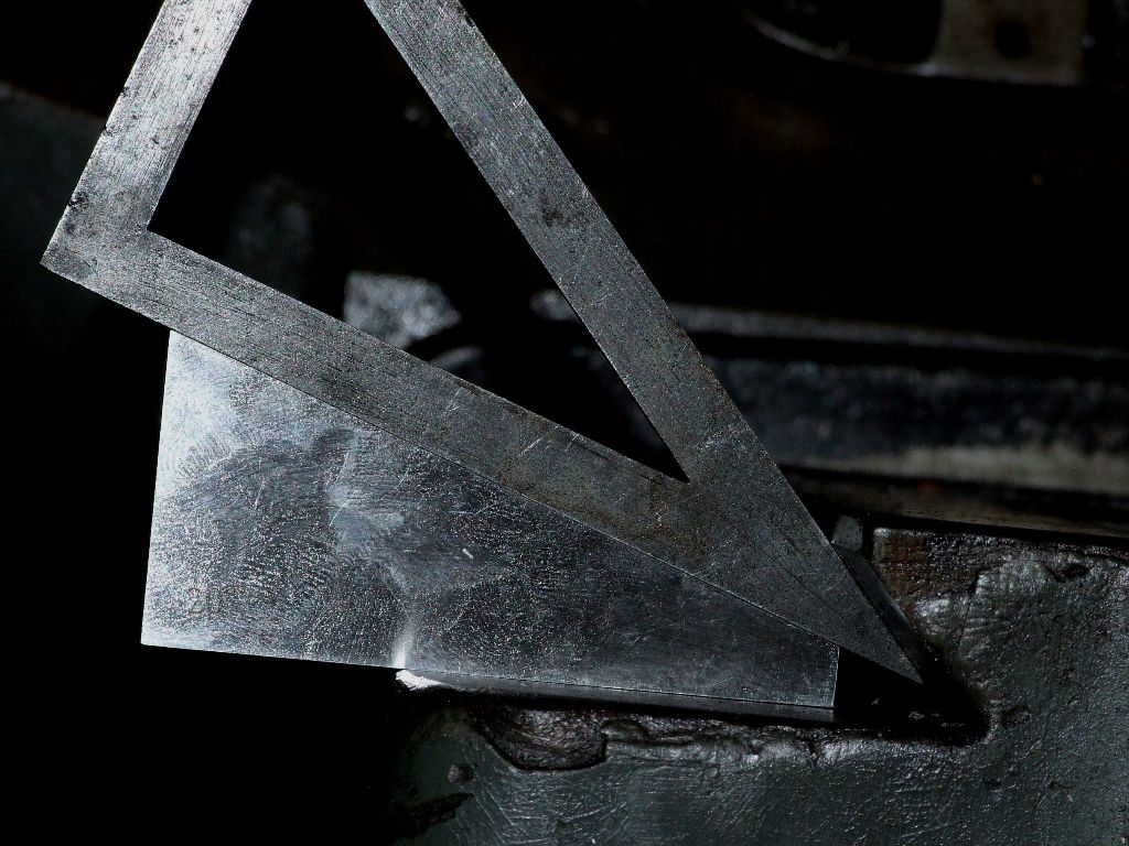
                                                Ketan: Definitely looks like 50º to me? Here's a 20º block and a 30-60-90 set square:

                                                bp_dovetail.jpg

                                                I suppose it is a Bridgeport clone, in the sense that it was built by Adcock and Shipley in the UK. teeth 2

                                                Andrew

                                                #205037
                                                Ajohnw
                                                Participant
                                                  @ajohnw51620

                                                  It's down to the pressure of the slide down onto the part it runs on. Dovetail slides usually have clearance at the top so as the gibs are adjusted tighter more pressure is generated in a downward direction as the angle gets more acute. On the other hand there has to be some angle to prevent lifting so it's a compromise. The other aspect is side forces. The more acute the angle the greater the force on the male part of the dovetail as well as downwards. I'm sure I have seen the maths in the past some where but in real terms I doubt if there is much difference between 60 and 55 and believe 55 degree dovetail cutters have been about anyway. 45 would give bigger wear areas and if the area below the slide was larger the psi would drop so there are other ways of compensating but it would require more general rigidity.

                                                  There are some books on the archive on lathe design. The best one that even mentioned harmonic oscillations on the spindle has gone. Also if I remember correctly head length – long so that bearing alignment errors produce less errors on the work which is pretty obvious anyway. One that is still there mentions using what is basically an attachment to finally size plain spindle bearings. That was common once. It even mentions just removing rather tiny amounts, more like scraping. It doesn't mention the complications with taper plain bearings, shows several bed styles but also the common 4 rail prismatic bed. Generally the saddle guides will pass either side of the head and tail stock.

                                                  Most high end lathes that are precision such as DSG and others use a prismatic bed with 4 V's. The inner 2 are for head alignment and the tail stiock. They are also massively built which is part of the reason for the finish that they can achieve even with shallow cuts. The other is bearings.

                                                  This is a drawing of the sort of bearing arrangements this ilk of lathes use that is adjustable. There are others

                                                  They run in pumped oil and the short distance between the ones at the front help with temperature effects. There are other arrangements with 2 at the front.

                                                  I was amazed when I saw a break down of one colchester head – just 2 taper rollers. It explains one or two things I have noticed about others using lathes in tool rooms. The students I have used have hardly been used at all and I'd guess those use that arrangement too. Talk about cheap.

                                                  John

                                                  #205039
                                                  John McNamara
                                                  Participant
                                                    @johnmcnamara74883

                                                    Hi Al

                                                    Its been a busy week for me…. Not enough time for design. However I have been thinking about a CNC, or pedal power if you insist, small lathe. How it is driven is up to the builder. the basic design is what matters.

                                                    This came to mind, I have a great book "Precision Machine design" written Professor Alexander Slocum who also wrote this free course at MIT where he works. A good foundation (No not lightweight) machine design course that is easy to understand with a minimum of maths.

                                                    As bearings are being discussed chapter 10 is on Bearings.

                                                    **LINK**

                                                    Regards
                                                    John

                                                    #205049
                                                    Ajohnw
                                                    Participant
                                                      @ajohnw51620

                                                      There isn't much help in fixing the problems in that John other than trying to design them out and no how to do that. I found the comment about bearings that look after themselves interesting. A lot of work was done on that area in the mid 60's but I don't know if it was ever fully worked out. It was noticed because some bearings by accident went on and on and on where as some didn't. It had also been noticed on some lathes, same make and model etc. Probably even constructed during the same phase of the moon but the reasons not clearly understood.

                                                      He does mention all of the problems but I suspect those will have been mentioned in this thread already but perhaps not so clearly.

                                                      There is plenty of info on some bearing manufacturers web sites as well complete with solutions but then comes the problem of implementing them at home. One other aspect is load – just what that is with various cut depths and material variations, weight of chucks and etc.

                                                      The problem with that bearing head stock arrangement is wear. Taper rollers tend to be better than angular contact but like most things compromises come into it.

                                                      John

                                                    Viewing 25 posts - 51 through 75 (of 86 total)
                                                    • Please log in to reply to this topic. Registering is free and easy using the links on the menu at the top of this page.

                                                    Advert

                                                    Latest Replies

                                                    Home Forums General Questions Topics

                                                    Viewing 25 topics - 1 through 25 (of 25 total)
                                                    Viewing 25 topics - 1 through 25 (of 25 total)

                                                    View full reply list.

                                                    Advert

                                                    Newsletter Sign-up