How to accurately machine a groove radius

Advert

How to accurately machine a groove radius

Home Forums Beginners questions How to accurately machine a groove radius

Viewing 14 posts - 1 through 14 (of 14 total)
  • Author
    Posts
  • #123950
    Tony Ray
    Participant
      @tonyray65007

      Morning,

      I'm making sheaves (pulleys) to carry 3mm wire rope in ally for a counterweight system. At the bottom of the groove i need a radius of 1.7mm (please don't quibble the design). Is there any alternative to grinding a form tool by eye ? I'll machine the flanks before putting in the groove.

      Thanks

      Advert
      #6777
      Tony Ray
      Participant
        @tonyray65007
        #123952
        Ady1
        Participant
          @ady1

          All the mass production piccies I've seen for making pulleys manually were on the big Herberts and they all used form tools

          The only possible alternative I can think of is a copy lathe, the modern equivalent being a CNC unit


          At the end of the day all "systems" need to be "tested" for accuracy when a new part is made which is standard procedure when you're making a thousand of them, and a pain in the neck when you're a dood who wants a single bespoke part

          It's the main reason why getting one bit from a machine shop costs 500 quid and getting 2 bits costs 550 quid

          This guy did it all by eye, the only alternative I can think of which would make it easier would be if you figured out a shadow board system

          Edited By Ady1 on 06/07/2013 10:03:25

          #123956
          Keith Long
          Participant
            @keithlong89920

            As an alternative to grinding a form tool, what about adapting the method used for making gear cutters. Turn a piece of silver steel to the radius you want, cut off a slice and mount it on the end of a shank like a button tool.

            Edited By Keith Long on 06/07/2013 10:15:00

            #123960
            Sub Mandrel
            Participant
              @submandrel

              Keith go there first. You can use loctite to fit the button on the end of a shank if you make a peg on the back of it, even though it will be very small. Used on aluminium it shouldn't overheat enouigh to break the loctite bond. Alternatively silver solder it onto the shank and quench as soon as the solder hardens.

              Neil

              #123961
              Ady1
              Participant
                @ady1

                Sounds like a great way to make a one hit cutter

                Lateral thinking!

                #123964
                John Stevenson 1
                Participant
                  @johnstevenson1

                  Get a ball bearing, braze it to a shank, quench it and grind it in half from the top.

                  Result perfectly circular form tool with all the correct clearances and hardened to boot.

                  #123976
                  Tony Ray
                  Participant
                    @tonyray65007

                    Gents,

                    Thanks I'll follow the button cutter route & use loctite as I'm not equipped to braze – though I could soft solder it ..

                    Off to the workshop !

                    #123979
                    Ian S C
                    Participant
                      @iansc

                      For the bale feed machines that I do the machine work for, we require 2 100 mm pullies for 6 mm wire rope, i used a form tool at first, but after two or three machines we desided that a flat bottomed groove is quite adiquate, done with a parting tool.

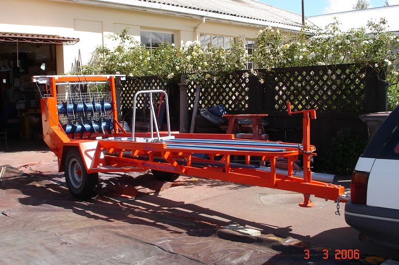
                      These bale feeders are a trailer type machine that gets loaded with two large square hay bales (about 4ft sq for the large size), this is towed around the padock and the hay is automaticly feed out on the ground for the stock to feed on. We also make a small one that takes a single 3ft sq bale, useful on lifestile blocks. Our largest one takes 5 large bales. When you have 3 or 4000 cows to feedeach day, a machine gets a fair bit of wear, but the pullies, and rope have not suffered. Ian S C

                      #123980
                      MICHAEL WILLIAMS
                      Participant
                        @michaelwilliams41215

                        No need to make buttons – just put the whole piece of bar for the cutter vertically or a little slanted in a tool holder with a side clamp .

                        Also possible to present cutter to work horizontally and over the top if more convenient .

                        Radius actually cut can be tuned slightly by changing angle of presentation of tool to work .

                        Also possible to do this sort of thing with end mills and indexing heads .

                        Edited By MICHAEL WILLIAMS on 06/07/2013 13:22:30

                        #123986
                        Sub Mandrel
                        Participant
                          @submandrel

                          > Our largest one takes 5 large bales. When you have 3 or 4000 cows to feedeach day,

                          And I really believed the Anchor Dancing Cows lived of fresh grass all year round

                          Neil

                          #124025
                          Ian S C
                          Participant
                            @iansc

                            dsc00151.jpgThis is one of the bale feeders Getting ready for delivery to one of the customers.  The mechanisim is powered from the right hand wheel,  larger machines, and ones that will only be towed by a tractor are hydraulicly driven.  Ian S C

                            Edited By Ian S C on 07/07/2013 11:58:00

                            #124162
                            Tony Ray
                            Participant
                              @tonyray65007

                              End Note:

                              Well I made a button tool and it worked beautifully. I didn't harden the button I superglued it in place before i remebered that i was going to. Anyway on alloy it has not shown any wear.

                              What would i do differently ? Spend more time thinking about the setup to get a better blend between the angled flanks and the radius at the bottom of the groove.

                              Its useful to know that a flat bottom groove would work too. I'm sure the baler application is a lot more demanding than mine.

                              Cheers

                              Tony

                              #124171
                              John McNamara
                              Participant
                                @johnmcnamara74883

                                Hi Tony Ray

                                A while back I made some cast iron pulleys with a groove very close to the 3.4 diameter of yours yours I milled the radius into the pulley edge with the side of a plain square end milling cutter. no ball end required.

                                In this case the pulleys had to be made to high precision better than .0005" run out (there were deep groove ball bearings fitted in a precision bored centre boss) A set of 6 in all about 120mm in diameter to be used in a cable driven parallel motion mechanism.

                                The method used was to mount the pulleys with bearings fitted on a shaft (A bolt) on a small angle plate then while rotating the pulley slowly the cutter was brought to bear at 90 degrees to the axis of the blank on the outer edge of the pulley blank while it was rotated at a about 2 rpm.

                                The rotation of the blank was achieved using a rubber friction drive applied to the edge of the blank with a small slow speed gear motor with a rubber drive disk turned up from stuff found in the scrap bin. It did not require a lot of power. A bit of a lash up but it worked.

                                The pulley blanks had been plain faced, I did not pre cut the groove as in this case all that was needed was to sink the centre of the radius about 2mm below the plain edge face. I cant remember exactly what depth of cut I used probably about 1mm per rotation of the blank until near the final dimension required then a couple of light finishing cuts

                                This method worked surprisingly well…. centering was not a problem because the pulleys were machined on their own bearings with the centre of the ball race fixed. The .0005' run out tolerance was bettered and the finish was very good. I did use a sharp endmill (Note only the side of the cutter was used not the end edges)

                                If you have a vertical mill and a rotary table and a cutter of the right size and length you could center the blank on the rotary table (You may need to pack it out to allow clearance for the milling chuck) then use the same methods as above. you would have to hand feed the rotary table.

                                Cheers
                                John

                                Edited By John McNamara on 09/07/2013 17:36:43

                              Viewing 14 posts - 1 through 14 (of 14 total)
                              • Please log in to reply to this topic. Registering is free and easy using the links on the menu at the top of this page.

                              Advert

                              Latest Replies

                              Home Forums Beginners questions Topics

                              Viewing 25 topics - 1 through 25 (of 25 total)
                              Viewing 25 topics - 1 through 25 (of 25 total)

                              View full reply list.

                              Advert

                              Newsletter Sign-up