Hole diameters for single point threading

Advert

Hole diameters for single point threading

Home Forums Help and Assistance! (Offered or Wanted) Hole diameters for single point threading

Viewing 17 posts - 1 through 17 (of 17 total)
  • Author
    Posts
  • #33876
    Joseph Noci 1
    Participant
      @josephnoci1
      Advert
      #558020
      Joseph Noci 1
      Participant
        @josephnoci1

        I have tried to find methods of defining the hole size for a particular thread to be single point cut in the lathe.

        This appears to always be based on thread engagement, which is influenced by the material being threaded, and the focus is strongly on tap life. So the hole is larger for aluminium than for a tough steel, etc.

        However, tap longevity is not really directly applicable to single point threading, so does this engagement issue still apply unmodified?.

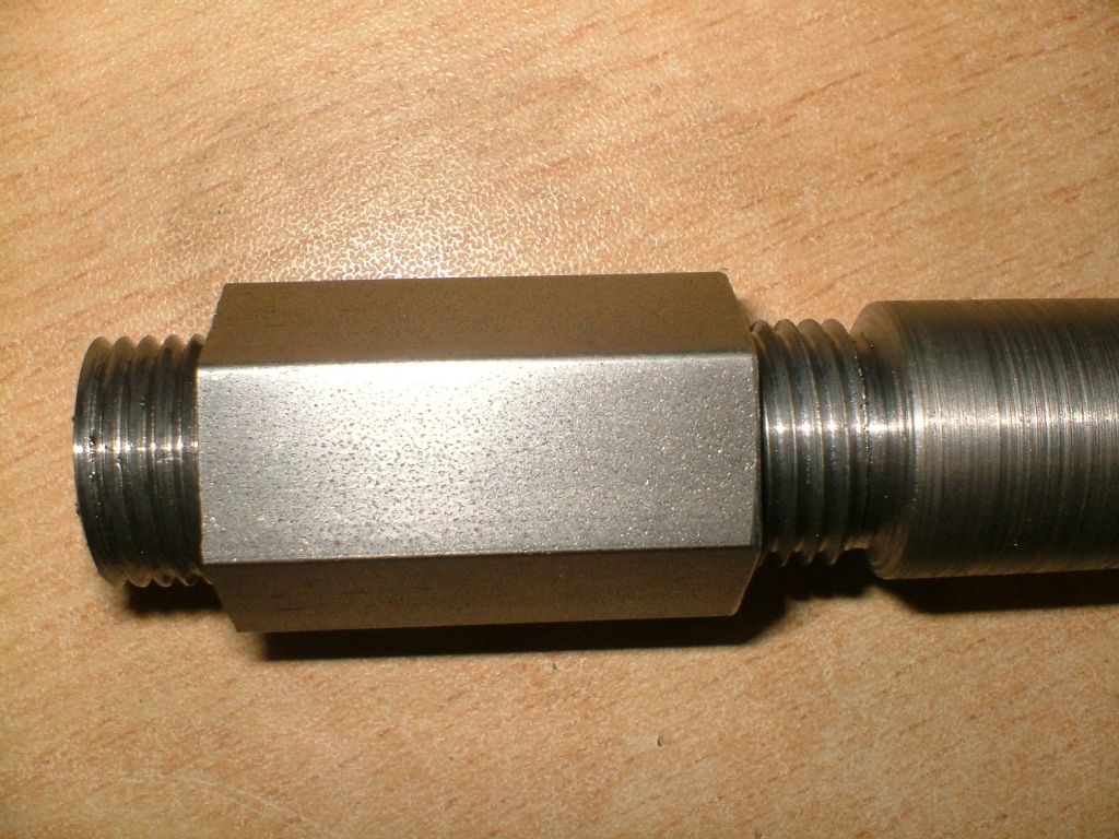
        I am internal threading a mating part that screws onto a M1.25 threaded stub, 34.5mm OD. The OD is the OD of the thread on that stub. The mating thread will be in EN8. The thread section on the stub is 30mm long. There is not a great load on the thread when assembled, but slop needs to be as low as possible.

        I would presume that I should therefore try to get as high a thread engagement as is possible. 80%? More maybe? I would assume that 80% or more should be easily achieved when single point threading? So do I just use 'ordinary' tapping tables and select 80% or better?

        Most tables don't list a 34mmxM1.25 size, but there calculators that do the job – So one could just faff about till the part threads on in a good enough fashion but I don't particularly like that approach – some science (or engineering) is applicable! What engagement should I start with for the 'best' fit possible, including a little faffing?

        Joe

        #558022
        Anonymous

          When single point threading I ignore tapping tables and percentage thread engagement. For internal threads I turn the bore to the theoretical core diameter, ie, assuming 100% thread depth. When screwcutting I aim for the theoretical thread depth, checking fit with a mating part. Once near the theoretical depth I take fine cuts, may be a couple of thou off the diameter. When checking fits it is important to do a spring pass and clean the thread with a fine brush. Almost invisible dust or swarf can be the difference between a nice fit and loose. Most of my single point threading is done with full profile inserts rather than HSS, so I can assume that the thread profile is correct.

          Andrew

          #558024
          Martin Connelly
          Participant
            @martinconnelly55370

            I was about to answer much as Andrew but he just beat me to it. Thread engagement below 100% is only relevant to tapping with a tap. The point of less than 100% engagement is to reduce the torque required to cut the thread and so prolong the tap life or prevent the tool snapping from excessive torque. The other thing to consider that some materials such as aluminium alloys deform when the tap is used and so a larger tapping drill will result in some material being deformed inwards into the peaks of the resulting thread and less being cut as the tap goes into the hole. Neither of these things is relevant to single point tapping.

            A similar thing done with dies is to start with a diameter slightly below nominal to reduce the torque required to cut the thread. Measuring the diameter after die cutting the thread will show that the diameter is slightly larger than the starting diameter as some material will deform outwards.

            Martin C

            #558027
            duncan webster 1
            Participant
              @duncanwebster1

              By slop do you mean axial? If so the thread engagement won't make any difference, and it makes surprisingly little difference to the strength within reasonable limits.

              #558030
              Ady1
              Participant
                @ady1

                Depends what its for

                I just go for 0.5 or 0.25 each side if its general stuff

                If its important I go for zero error/perfect bespoke fit which takes longer

                The threads that always impressed me the most were gun breeches

                Edited By Ady1 on 12/08/2021 22:55:21

                #558040
                JasonB
                Moderator
                  @jasonb

                  Although M34.5 is not standard so won't be listed, if you can find the information for any other 1.25mm pitch thread then just make allowance for the difference between the two nominal diameters. ( note it is the diameter that should be prefixed by the M)

                  As Howard says it's the flank contact that makes the difference between a sloppy thread or not so it is more a case of how deep you cut and as has been recently discussed that can depend on the form of your tool depending on if it has a flat, pointed or rounded form.

                  #558047
                  Joseph Noci 1
                  Participant
                    @josephnoci1

                    Thanks to all for the comments and advice. The cutter I am using is an 16IR-A60 carbide insert. The tip radius appears very small under the microscope – maybe 0.1mm ? Low slop was a poor descriptor to use for what I am trying to achieve and strength is not the concern, but good coaxial alignment is the main aim. I will make one or two test rings and thread for best fit…

                    Thanks chaps!

                    Joe

                    #558052
                    Tony Pratt 1
                    Participant
                      @tonypratt1

                      Joe, 16IR-A60 is not a full form insert, as you say the tip has negligible radius so just using the theoretical core diameter will be I think problematic. A male gauge or mating part would be a good test of fit.

                      Tony

                      #558065
                      Anonymous

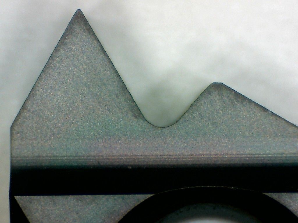
                        To expand on the reply by Tony; this is a 16ER-AG60 insert:

                        16er-ag60_me.jpg

                        It is an external insert intended to cut a range of ISO metric pitches. The nose radius will be set for the smallest pitch in the range covered. For larger pitches the radius will be too small and the depth of cut needed will be larger than theoretical to compensate. However the outer diameter will remain the same; for internal threads the core diameter will remain the same.

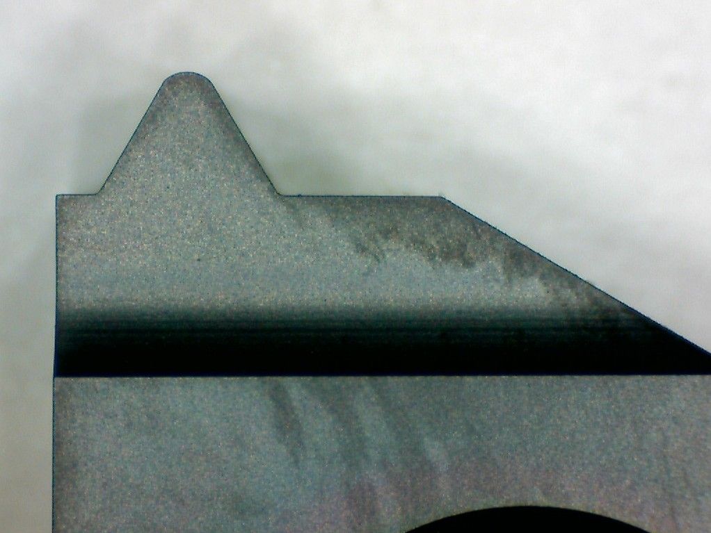
                        In contrast this is an 16ER 2.0ISO insert, full profile intended to cut only 2mm pitch external threads:

                        16er-2.0iso_me.jpg

                        Note the larger nose radius. I will be using this insert later today as I have some M16 threads to screwcut.

                        Andrew

                        #558070
                        SillyOldDuffer
                        Moderator
                          @sillyoldduffer

                          Fools go where angels fear to tread, but it's never stopped me before!

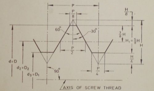
                          The form of a metric thread, and relative dimensions, are defined whether or not the diameter is a preferred size or not. Details in Machinery's Handbook, and similar tomes. I pinched this chart off the web:

                          basic-thread-form-for-iso-metric-and-unified-threads.jpg

                          Internal Thread at top, external thread below. For all metric threads H = 0.866 × pitch. It's usual for metric threads to be cut or rolled rounded at top and bottom rather than sharp as shown in the diagram.

                          Thread tolerances are somewhat complicated, ranging from very tight to downright slack, such as threads that are going to be plated. More info on Tolerance Positions and Tolerance Grades here, but I don't think Joe need read it!

                          A thread made as shown in the diagram would be an uncomfortably tight fit, hard to assemble, and any error in it's manufacture would cause it to jamb. Force fits aren't acceptable if the joint is meant to be unscrewed, so practical threads are cut with slightly oversized 'V's, in effect broadening the bold line. The difference can be seen by comparing DIY store zinc-plated studding with the same sized thread on an Allen Bolt. Studding is crudely made and slack; the Allan Bolt should be much cleaner, well formed and tight fitting in it's socket.

                          I think Joe can control how tight his thread fit is simply by cutting less deeply than normal. Cutting less than 0.866 × pitch will create an over tight thread, exactly 0.866 × pitch will fit with difficulty, and cutting deeper than 0.866 × pitch will create an increasingly slack fit. I'd make the internal thread first getting as close to 0.866 × pitch as I can measure (not sure how I would do that!), and then use the internal thread as a gauge to make the external thread a tight fit. Could be very tight, needing a strap wrench, or hand tight, as required.

                          EN8 may not be a good choice because a smooth surface finish is vital for a tight thread fit intended to be screwed and unscrewed, and EN8 often tears roughly when cut.

                          A precision collar preventing slop might be an alternative to hard to make precision threads.

                          Dave

                          #558073
                          pgk pgk
                          Participant
                            @pgkpgk17461

                            IIRC 'Toms Techniques' on YouTube did a vid showing how to make and use a form tool for a specific thread pitch including the helix angle of the tool worked out for Machinery Handbooks charts

                            pgk

                            #558075
                            Anonymous

                              Posted by SillyOldDuffer on 13/08/2021 10:00:11:

                              …….EN8 often tears roughly when cut…….

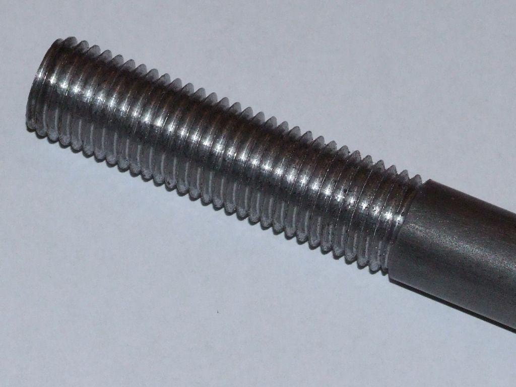
                              Agreed when turning, high surface speed often cures the problem. Strangely though the same isn't true when threading. Here's an M16 thread in EN8 I made earlier:

                              m16 thread.jpg

                              It's not a super smooth finish but works fine as a drawbar on the horizontal mill. The thread was cut on an imperial lathe, so I couldn't use my high speed threading attachment. Instead I was slow 'n' steady with the half nuts always engaged, 85rpm I think.

                              Incidentally H=0.866P is the theoretical depth of the 60° triangle, it's not the same as the actual thread depth, that's 5/8H, unless one uses Zeus.

                              Andrew

                              #558131
                              old mart
                              Participant
                                @oldmart

                                You will find that any given pitch of thread is the same depth, ie, a 6mm X 1mm pitch thread depth would be identical to a 20 X 1mm pitch thread. So if you need to make a unique diameter thread with a standard pitch, you can use the figures for that pitch of thread. If possible, you can get a perfect fit by using the mating part as a gauge and creep up on the last bit. If the fit is critical, but the mating part cannot be used as a gauge, you could make a threaded gauge of the same size to use instead.

                                **LINK**

                                #561178
                                Ady1
                                Participant
                                  @ady1

                                  An M18 x 1.75 I'm working on at the moment

                                  If it looks ok then it tends to be ok

                                  I only worry if its something critical

                                  The bit to remember is the higher the TPI the shallower the thread depth, no matter how big the job is

                                  dscf3314.jpg

                                  Edited By Ady1 on 04/09/2021 10:30:06

                                  #561218
                                  Joseph Noci 1
                                  Participant
                                    @josephnoci1

                                    I seem to have managed…old and new shafts.jpg

                                    Joe

                                    #561242
                                    Ady1
                                    Participant
                                      @ady1

                                      Run it up to 50 rpm to get the chuck on and off

                                    Viewing 17 posts - 1 through 17 (of 17 total)
                                    • Please log in to reply to this topic. Registering is free and easy using the links on the menu at the top of this page.

                                    Advert

                                    Latest Replies

                                    Viewing 25 topics - 1 through 25 (of 25 total)
                                    Viewing 25 topics - 1 through 25 (of 25 total)

                                    View full reply list.

                                    Advert

                                    Newsletter Sign-up