Hemingway Kits filing Machine

Advert

Hemingway Kits filing Machine

Home Forums Workshop Tools and Tooling Hemingway Kits filing Machine

Viewing 21 posts - 1 through 21 (of 21 total)
  • Author
    Posts
  • #512927
    Buffer
    Participant
      @buffer

      Hi

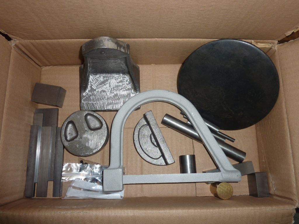
      I thought I would post a few pics and some info on the Filing Machine from Hemingway Kits.

      p1040899.jpg


      This is what you get plus some build notes and good drawings.


      Edited By Buffer on 11/12/2020 19:49:32

      Edited By Buffer on 11/12/2020 19:50:01

      Advert
      #20059
      Buffer
      Participant
        @buffer
        #512974
        Ady1
        Participant
          @ady1

          Someone here doing one ATM

          #513291
          Buffer
          Participant
            @buffer

            So I got some work done on the machine this weekend.

            p1040906.jpg

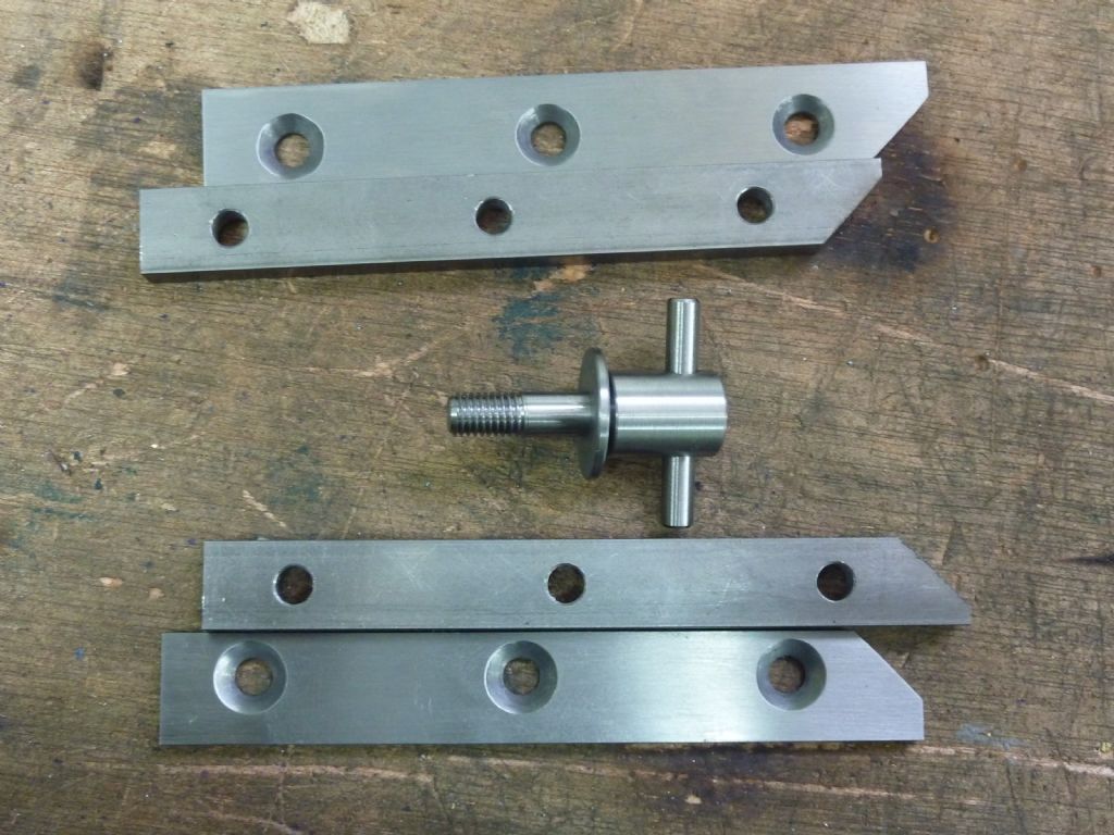
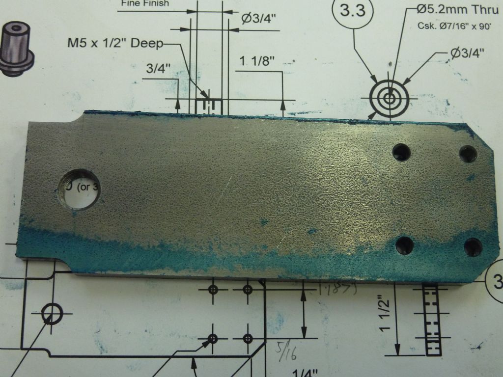
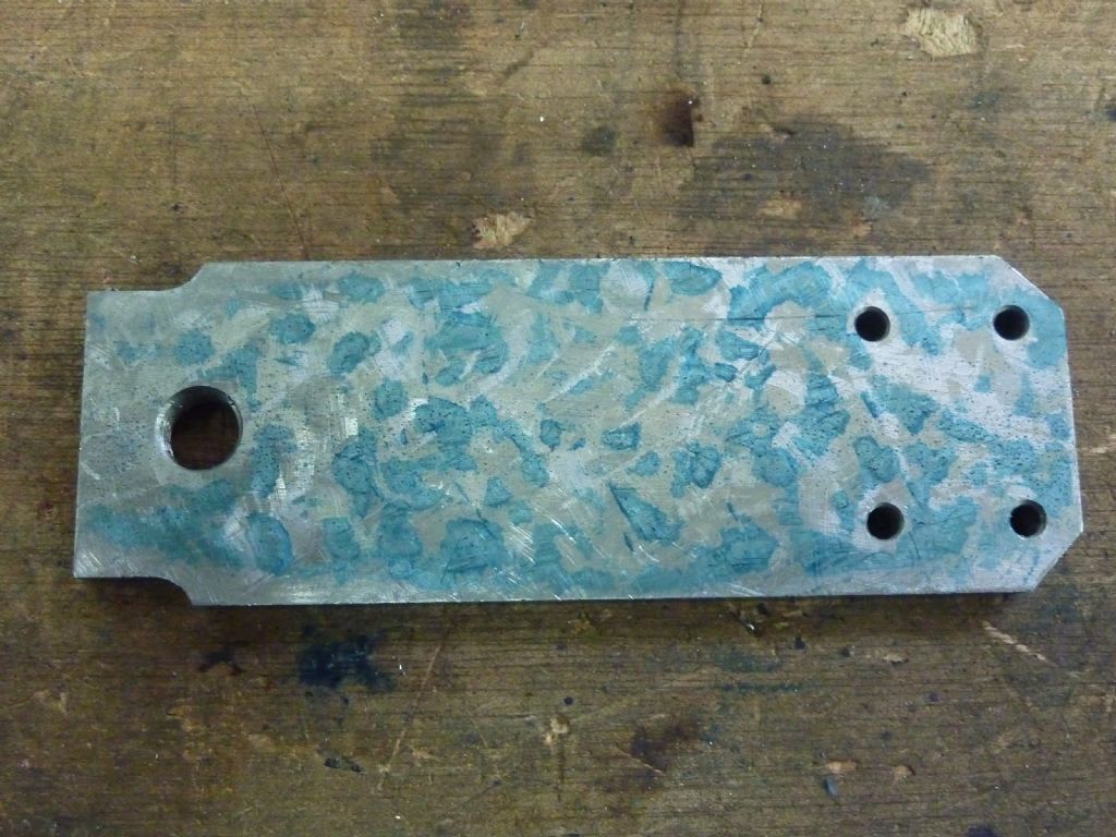
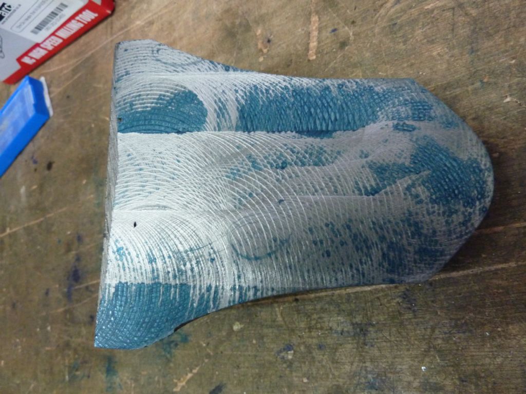
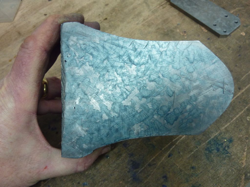
            The piece below is the bit that goes up and down sliding on the main casting. It is supported and guided by the bits above. I rubbed it on the surface plate and as you can see there is very little contact.

            p1040903.jpg

            After about half an hour with a carbide paint scraper blade that has been soldered to a length of steel rod it looked like this, which is looking much better.

            p1040905.jpg

            This is the main casting that was cut with a 5 tooth carbide shell mill from Arc

            p1040907.jpg

            #513298
            Buffer
            Participant
              @buffer

              The 5 tooth shell mill actually gives a very nice finish when you want it too but I knew I was going to scrape this bit so I didn't hang about with it.

              This is the casting after about an hour with the home made scraper

              p1040909.jpg

              #513303
              Buffer
              Participant
                @buffer

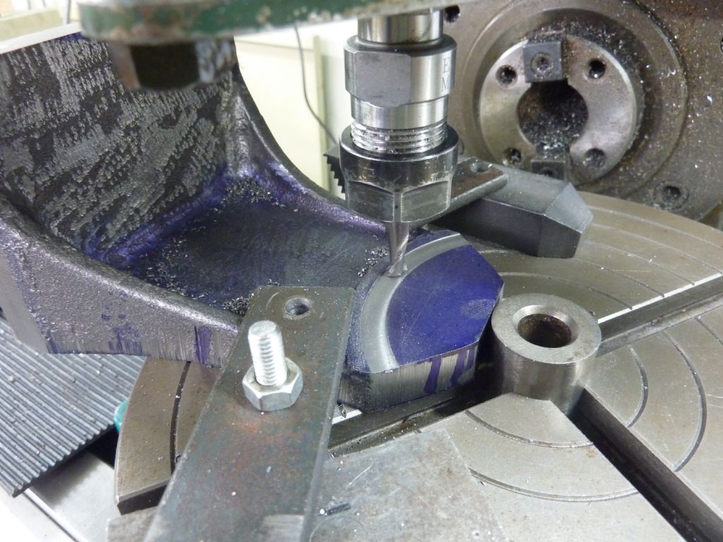
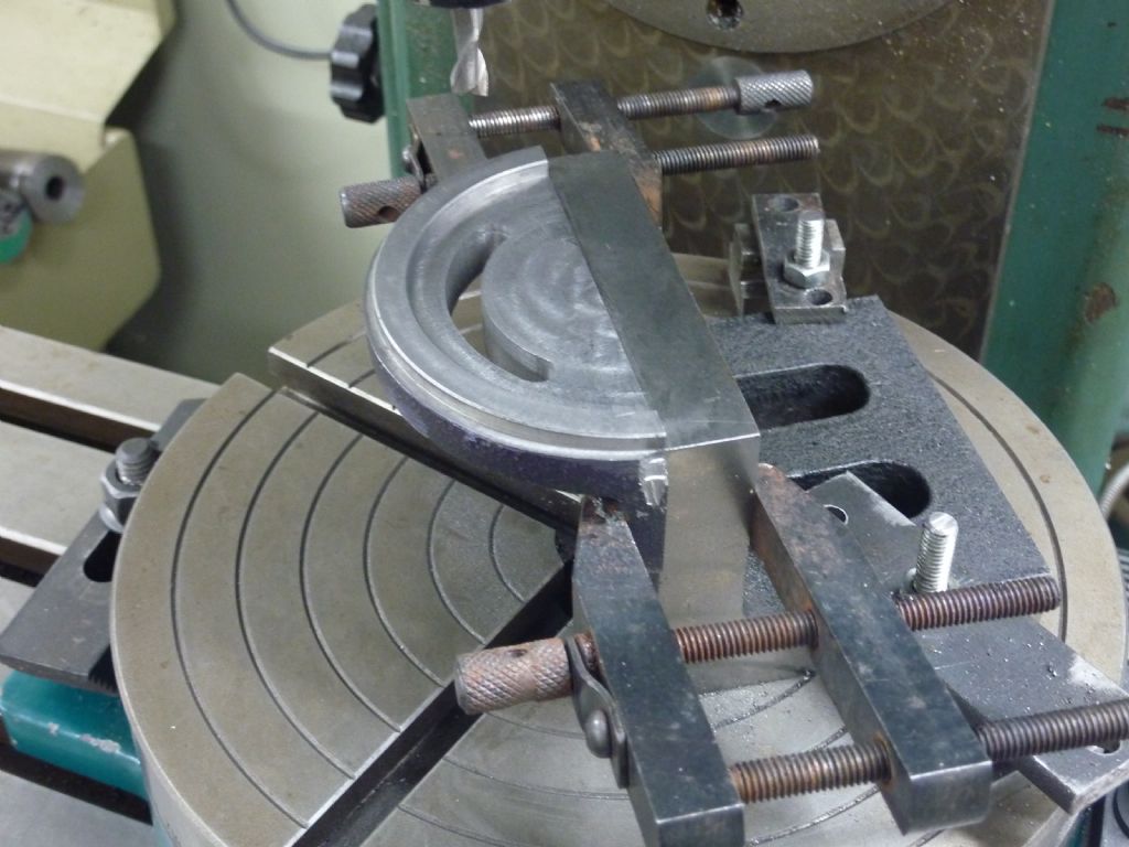
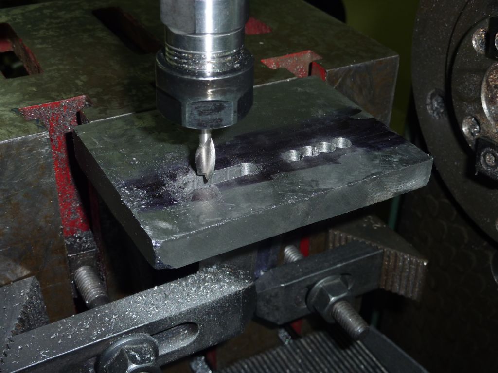
                The main casting needs a curved slot with its centre 1/2 an inch off the casting in the fresh air. So I took a little bit off the top of the casting to get it to the exact length and then pushed it up to a 1 inch cylinder that was in the middle of a rotary table. I centred the table using the Osbourne manoeuvre. This works really well and I only had to do it 3 times and it was bang on as far as I could tell.

                p1040910.jpg

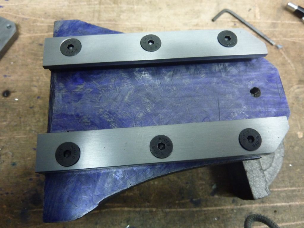
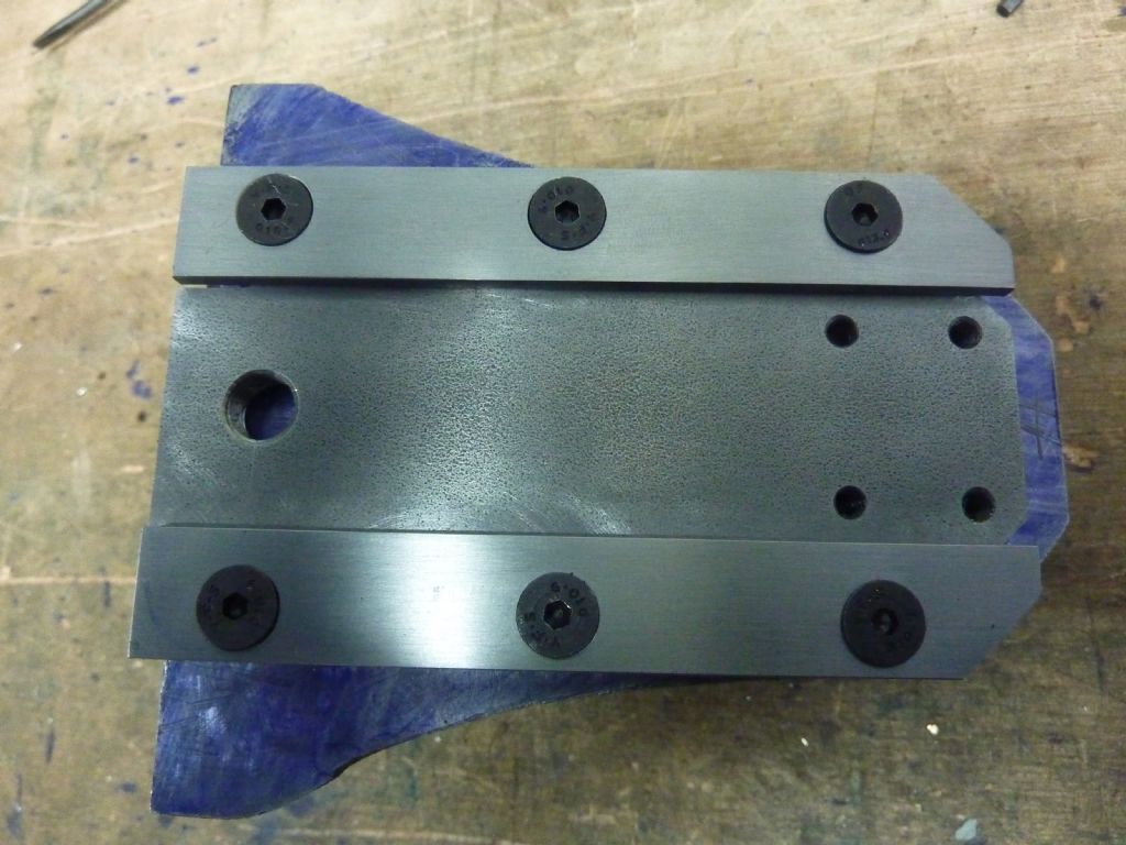
                I then flipped it over and fixed it to an angle plate squared it all up and drilled the holes to hold the guide bars. I was really pleased when this came out spot on as I didn't mark out any of the locations just used the dro.

                p1040912.jpg

                p1040911.jpg

                So that's it for now, back to work tomorrow but hopefully I will get a little bit more progress in the week.


                Edited By Buffer on 13/12/2020 18:55:26

                #513364
                not done it yet
                Participant
                  @notdoneityet

                  Looking good. I’m hoping my surface grinder will provide very flat surfaces – but they would likely be better with scraping the surface(s) for oil retention.

                  #513759
                  Buffer
                  Participant
                    @buffer

                    I got a bit more done last night. It wasn't the easiest to set up as the centre of the arc is off the casting by 3/16th of an inch. With hindsight it would have been a lot easier to just slip a piece of 316th steel between the casting and the angle plate but I only thought of that this morning. Anyway I got a good piece that fits very nicely to the main casting.

                    p1040918.jpg

                    #513776
                    not done it yet
                    Participant
                      @notdoneityet

                      The second one is often easier than the first.🙂

                      #513784
                      S.D.L.
                      Participant
                        @s-d-l

                        Nice build log, keep it coming please.

                        Steve

                        #513874
                        Buffer
                        Participant
                          @buffer

                          Thanks guys.

                          Well Wifey went to work today and the kids seemed happy scrapping with each other so I sneaked out to get another bit knocked off.

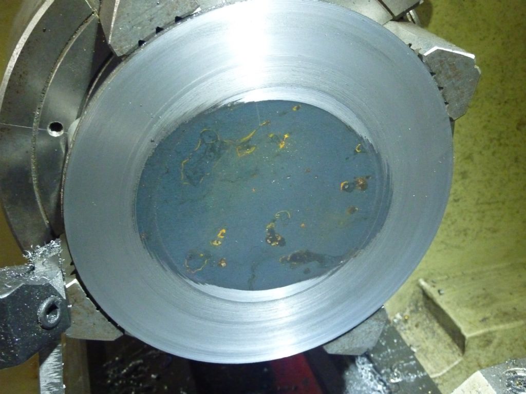
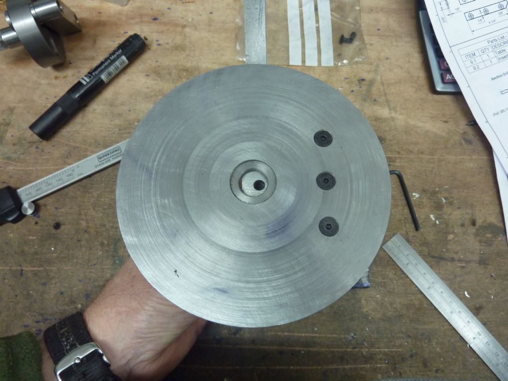
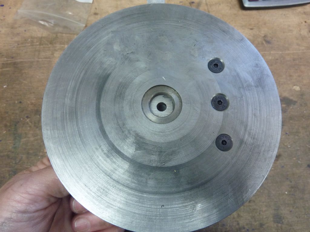
                          Now the instructions do say that you should give the table a skim over to get it flat. The piece is punched out so it has clearly taken on a bit of a curve. It's not obvious by looking at it so I wouldn't worry if your 4 jaw can't cope but mine can so I gave it a long going over. You can clearly see here that the middle is a bit lower than the edge. It's not a lot though probably less than 1/2 a mm.

                          p1040919.jpg

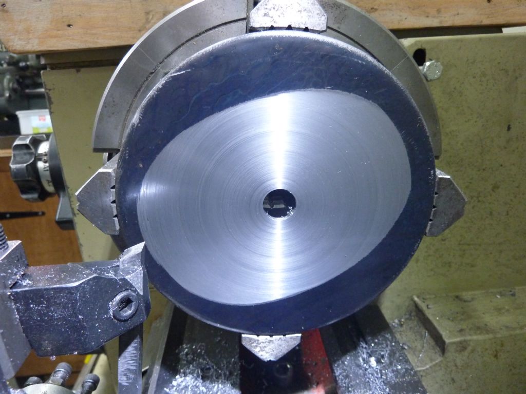
                          This is the other side and its pretty obvious but the middle is now being cut before the edge. I only cut enough to get a flat surface for the casting to bolt to it.

                          p1040921.jpg

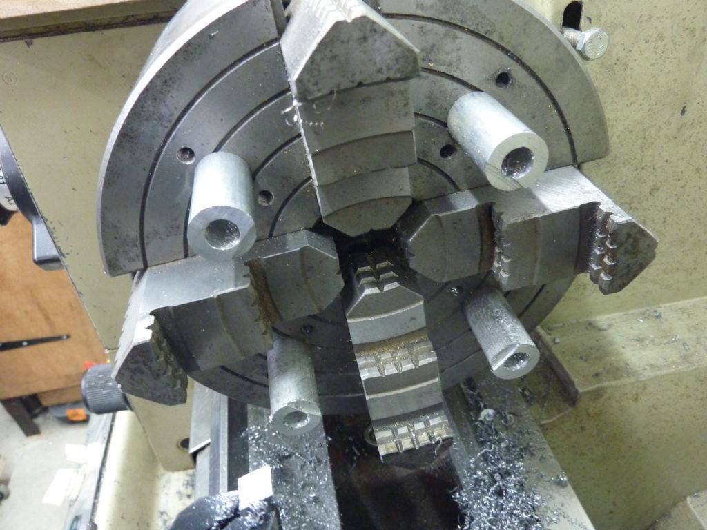
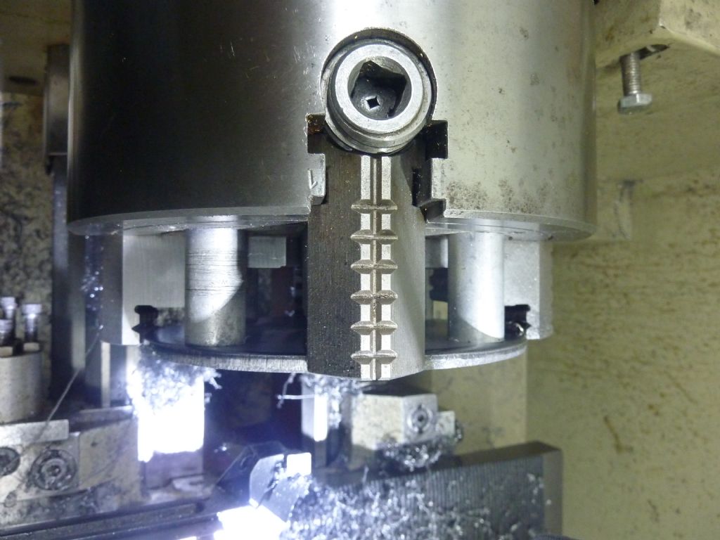
                          A while back while I was making the smoke box for a loco I did what some might see as vandalism. I drilled into my best four jaw chuck so I could mount posts on it. I know I could have used soft jaws and I do have a bearing mounted on a tool post but I did it anyway and it has been very useful.

                          p1040924.jpg

                          p1040922.jpg

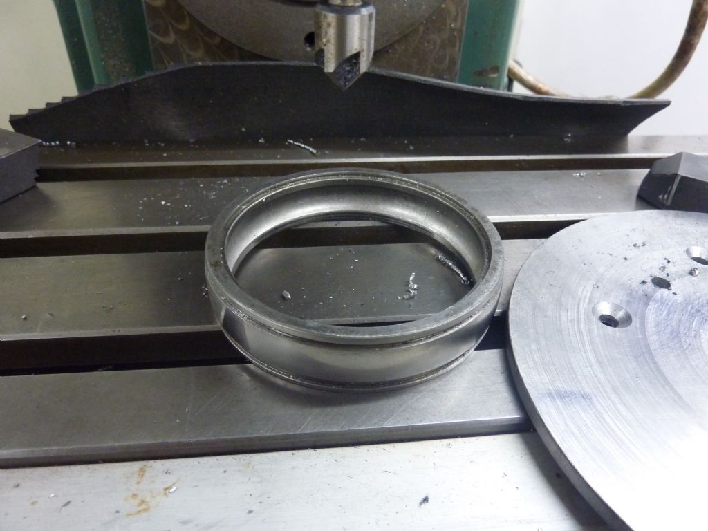
                          I used an old bearing outer as a parallel whilst drilling the mounting holes. I could of used normal parallels just as easily but there is an agricultural engineering business behind where I live and they always chuck big bearing in the skip so why not.

                          p1040926.jpg

                          #513879
                          Buffer
                          Participant
                            @buffer

                            Well it seems there might be a little error in the drawings.

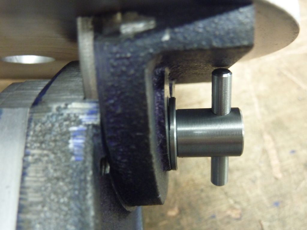
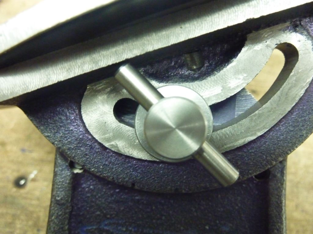
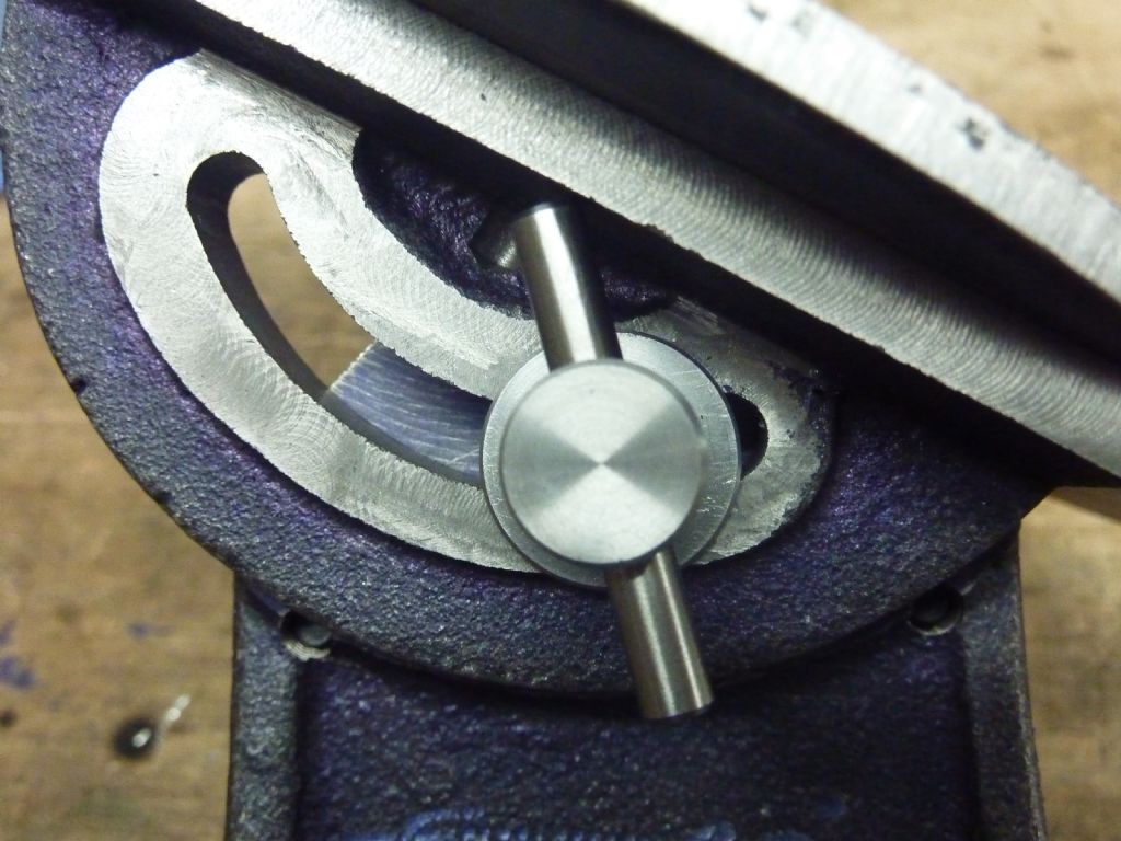
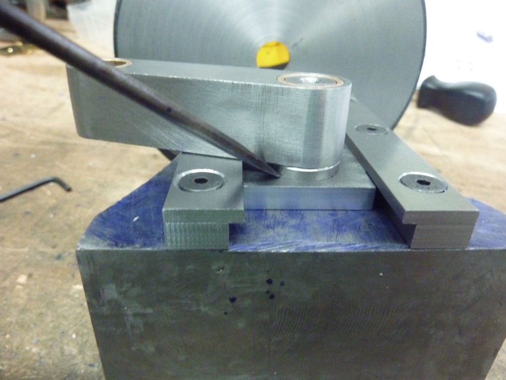
                            The screw that clamps the swivel up tight impacts with the the casting. I might be trying to tilt the table more than it is designed to do but made to the drawing it does hit the casting. It's not a problem yet as I think most of my filing will be done at ninety degrees. But if you want to tip the table over a a fair bit then make the thumb screw longer or make the tommy bar loose like you would find on a vice.

                            p1040927.jpg

                            p1040928.jpg

                            p1040929.jpg

                            #513908
                            Nigel Graham 2
                            Participant
                              @nigelgraham2

                              Fine project there!

                              I've been pressing on withy my Hemingway kit too – the 'Worden' tool & cutter grinder.

                              I did drop two, related clangers , luckily recoverable.

                              The table is tiled by three cams – sheet-steel discs screwed eccentrically to shouldered bushes that fit a cross-shaft on assembly. I turned all small parts a while ago, queuing them for cross-drilling and tapping the grub-screws holes on a shared second-operation set-up on the mill.

                              And so unto the cam plates, yesterday and today, and the clangers. (Without a soup dragon in sight.)

                              The cam plate blanks are nibbled-out with two 3mm holes that the drawing says are 2 " apart. The booklet with the drawings assumes making them entirely on the lathe, so these holes are for screwing them to a wood backing-plate for holding on a faceplate or 4-jaw chuck.

                              I elected to do all except trimming the nibbled edges on the mill, so faced both sides of a slice of aluminium bar in a 4-jaw SC chuck, transferred it still in the chuck to a nose-piece on the rotary table locked and set by a swinging-arm centring indicator (from Machine-DRO), and went into battle with the resulting loss of working height under the spindle.

                              Knowing I could rely on the accuracy of Hemingway's prepared sheet-metal parts, I took the drawing's stated 2 inches spacing for those holes at East and West as gospel, drilled and tapped the disc M3 for them, added a third at the South, another in the centre, 2 to align with the 3mm screw holes that will hold the plates to the bushes, and a pilot for the shaft hole.

                              All courtesy of the DRO (also Machine-DRO), and care always to wind right back then wind to position, from the same directions. My mill, a second-hand Myford VMC, has a fair amount of backlash and a strange "jumpy" bit in the middle of the long travel.

                              Started to screw the stack of blanks to the jig with the first 2 M3 jig-holes….

                              '

                              Clanger One.

                              They were slightly too far apart….. I had to enlarge the punched holes by 0.5mm. The problem? I had not verified the plates! The drawing innocently said 2 inches apart, as all dimensions except fastenings are in inches; but if working to the building notes that distance is not critical and they were actually 50mm apart!

                              Sorted that by careful enlarging, re-fitted the stack to the jig; drilled the other plate holes and added the extra screws.

                              '

                              Shaft hole next. Stop. Think. Examine drawing.. Opened up hole in stages; all tools directly in the R8 collets due to the lost head-room. Added further clamps as the drilling showed the tower of metal was not very rigid.

                              Next, the boring-head; a nice bit of kit, unknown make but labelled "Made in France for Gamet", and metric feed. I bored through all three for the bush with the smallest (by only a few thou) diameter mounting-shoulder; reducing the other two bushes later on a temporary mandrel.

                              Phew! Finally, I transferred the chuck / jig / plates assembly to the lathe to clean the edges.

                              '

                              Now Clanger Two appeared.

                              The jig was right but the cam stack was some way off-axis, shown by the central M3 screw orbiting. After all that careful planning, setting-up and machining. The nibbling and a stock edge-scar had hidden this previously.

                              What the…? My comments were rather less melodic than the knitted animals' conversations.

                              Resigned to reducing the cams' finished diameters, but I think not functionally, I moved the jig and stack to the independent 4-jaw, centred by the middle hole, trimmed the edges.

                              Finally, I milled off the segment specified, to clear the optional feed-screw. I have not bought that but it's sensible to allow for it at this stage. Luckily I'd marked the cutting-line by centre-drilled dimples before the disturbing, for simple re-aligning.

                              '

                              I have thought hard and honestly cannot see where It had gone wrong. Probably, I mis-read the vital X-travel on the mill so set (X = 0) in the wrong place, but won't know until I test the rotary-table again, having left the machine locked back at (0, 0) by DRO.

                              Possibly, the punched wood-screw holes were slightly off-centre originally, not affecting the intended method of machining nor the cams' function but doubling the " error " if I had accidentally overturned the stack in re-fitting it to the jig.

                              At least I hope it was just my setting error; and not some effect of that sticky bit of travel…..

                              #514061
                              Buffer
                              Participant
                                @buffer

                                Nigel I have just sent you a message.

                                #519659
                                Buffer
                                Participant
                                  @buffer

                                  Its been a while since I posted on here. I wasn't able to get anything done until recently as I had the dreaded Covid over Christmas. I felt so unwell and I have only recently felt well enough to get back into the workshop.

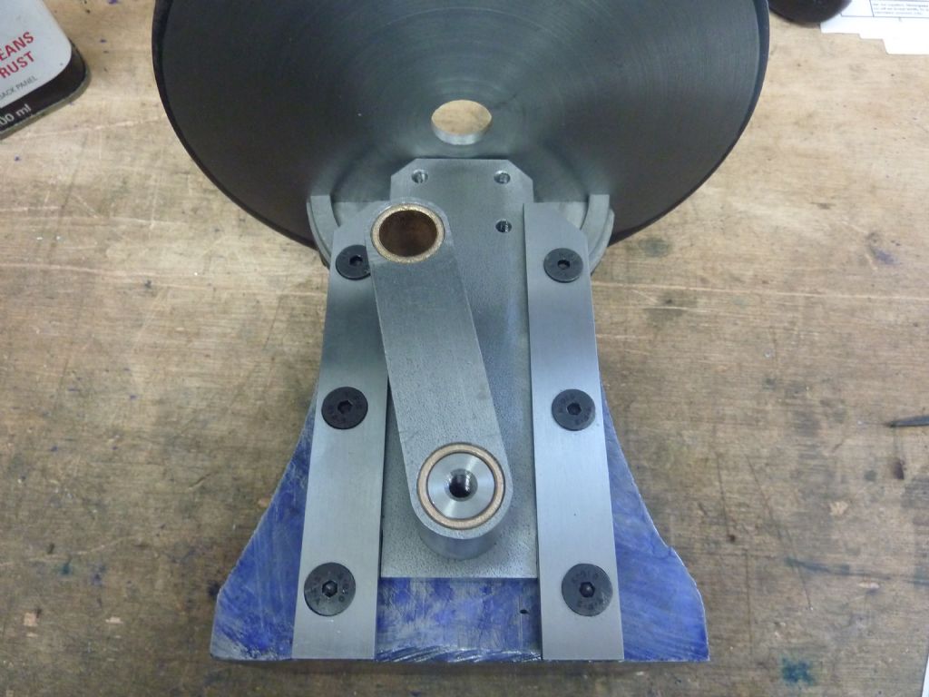
                                  So I got the connecting rod finished. It wasn't difficult I just drilled and reamed the holes to size and then pushed the bearings in using the vice. I roughly shaped the ends in the milling vice using a pin through the hole and then finished by filing.

                                  p1040930.jpg

                                  Here it is fitted to the rest of the machine. It's very important that the six screws are countersunk below the level of the surface, there is virtually no clearance of this crank over them.

                                  p1040931.jpg

                                  The flange on this pin has to be made accurately or even better slightly thicker. If you get this wrong you'll have to make it again or fit a washer. Funny thing is it's not given on the drawings you have to do the maths to get the size which to me seems a bit odd for such an important dimension.

                                  p1040933.jpg

                                  #521110
                                  Buffer
                                  Participant
                                    @buffer

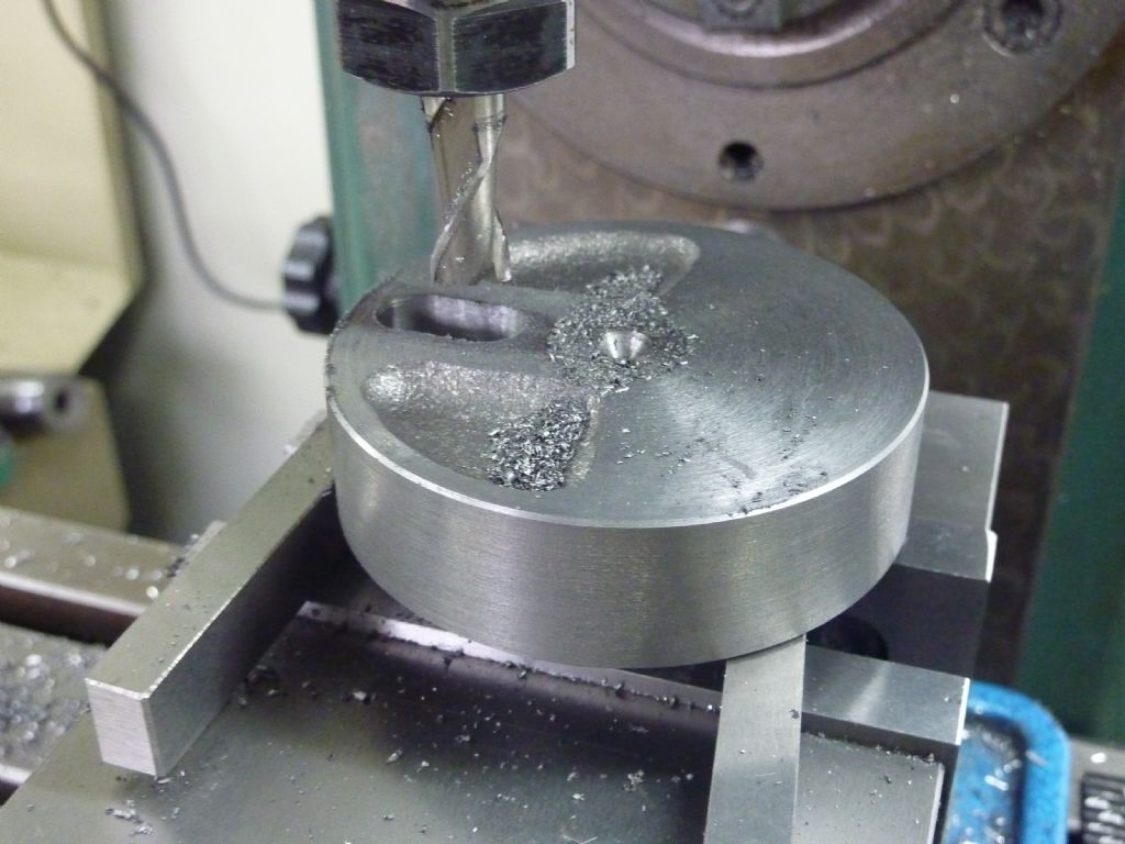
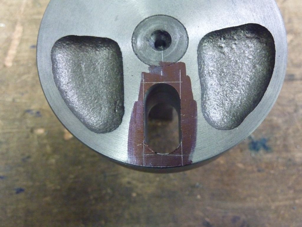
                                    It was Wife's turn to teach the kids so I sloped off for a few hours. I got the flywheel made by fitting it onto the centre shaft then used that in the lathe to turn the flywheel to size. It needs a square ended slot through it for the drive pin. I drilled out most of the slot then just finished it off with a slot drill. It went nicely as it's a cast iron flywheel.

                                    p1040934.jpg

                                    This is exactly the sort of reason why I want a filing machine. The slot is supposed to have square ends and I hate doing this sort of job.

                                    p1040935.jpg

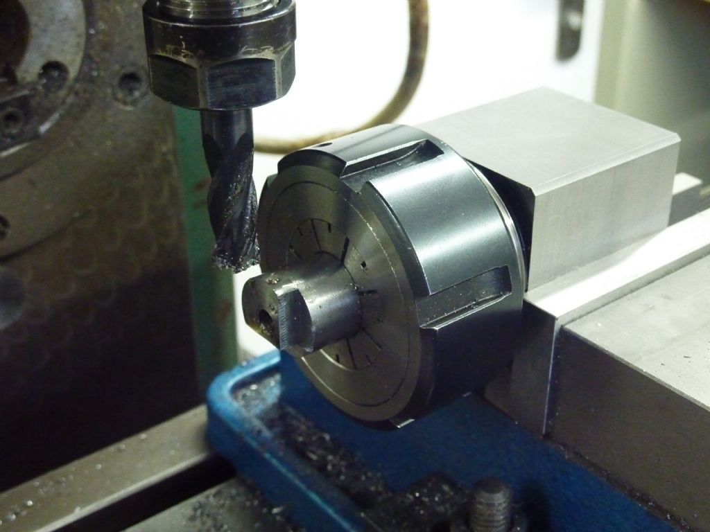
                                    I used a Stevenson's Block to cut a square on the end of the drive pin. it was dead easy with this great little tool.

                                    p1040936.jpg

                                    I then milled six flats on the end of the drive rod again dead easy with a Stevenson's Block from Arc. However this turned out to be a less accurate item than I had hoped. The flats weren't all the same size which was annoying. It wasn't a lot but it was enough to be visible.

                                    I then just had to slot the base to fit the Myford cross slide and I could fit it and give it a spin. It was easy to fit but you have to be really careful to make sure you don't give your lathe bed or saddle a good wack. The tool has to be carefully fitted so that the sliding part goes down between the ways. I then locked the saddle and cross slide. The lathe was put in its slowest normal speed with the clutch slowly eased in and away it went.

                                    p1040938.jpg

                                    There's not much more to go now Its really just the fittings to hold files and the aluminium bow for the saw blades. I've got two days of school work now so I guess I wont be out again until Friday.

                                    #521151
                                    not done it yet
                                    Participant
                                      @notdoneityet

                                      A ‘lever bolt’ (just ‘goggle’ it for lots of examples) might be a better alternative for that clamping screw for holding the swivel. Not bench made but reasonably cheap and effective. Mostly metric, mind. I change the bolt with a stud (with metric thread on one end and thread required on t’other).

                                      #522845
                                      Buffer
                                      Participant
                                        @buffer

                                        I managed to do what I thought was going to be the hardest part of this build which for me was the aluminium bow shaped casting.

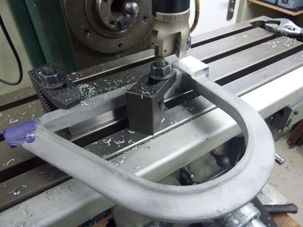
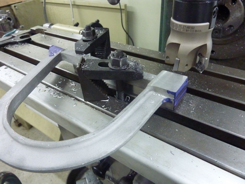
                                        I set it up as flat and level as I could and then machined a reference surface along the long centre portion. I could then flip it over onto a parallel to get the important end done.

                                        p1040940.jpg

                                        p1040941.jpg

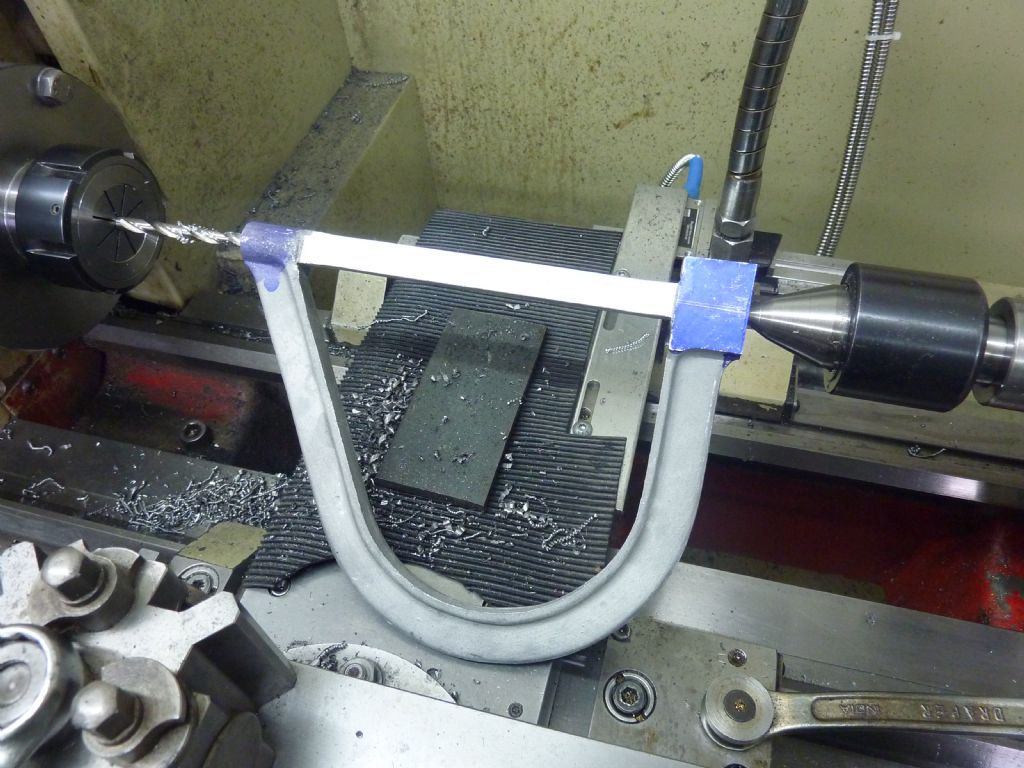
                                        One job I wasn't looking forward to was drilling a hole through both ends because they need to line up. I followed the instructions that tell you to centre pop each end then drill it on the lathe like this.

                                        p1040942.jpgYou then just flip it around to do the other end. It worked reasonably well but it is a little bit out. I don't think it would matter though for sawing and filing.

                                        I finally got the bow fitted to the machine and couldn't believe there was a mistake. My hole I had drilled was 1/8th of an inch off centre but I knew the problem wasn't with the bow.

                                        p1040944.jpg

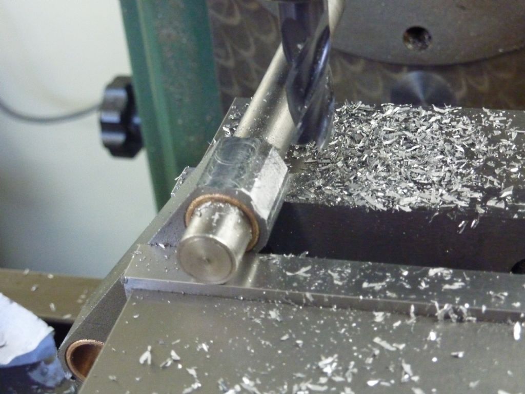
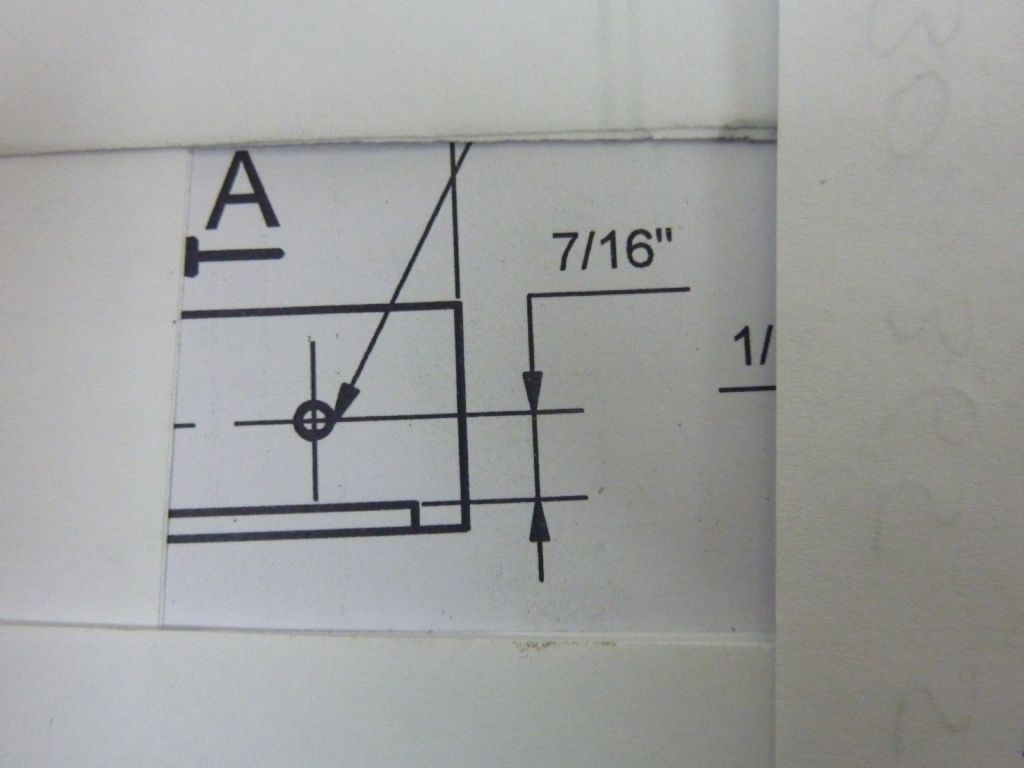
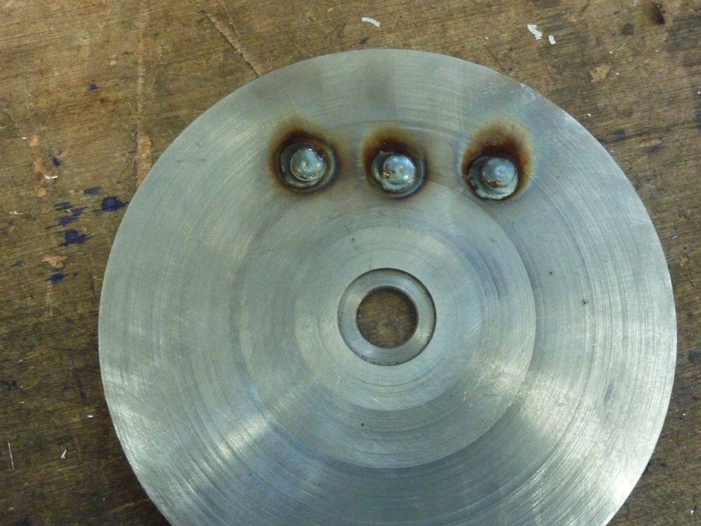
                                        The problem was I didn't drill the holes in the table mounting bracket in the correct place. I didn't read the drawing correctly the 7/16th is not from the edge of the part. D'oh! Lucky I've got a MIG welder.

                                        p1040945.jpg

                                        #523150
                                        Buffer
                                        Participant
                                          @buffer

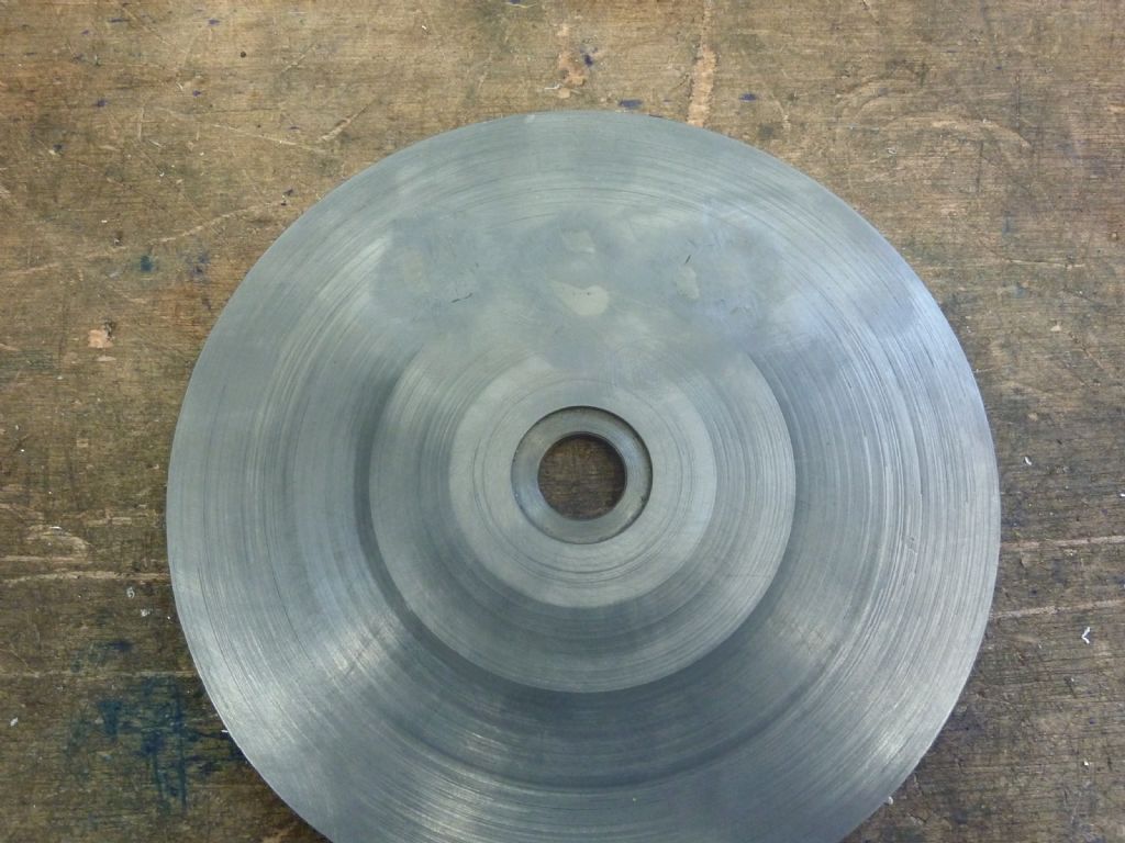
                                          I got the holes MIG welded up and then I milled the mess flat to the table. I think it looks worse in the photo than it actually is. So with the holes re drilled it all goes together nicely. It wont be long now before I can give it a go.

                                          p1040947.jpg

                                          p1040949.jpg

                                          p1040950.jpg

                                          Edited By Buffer on 27/01/2021 22:10:09

                                          #523156
                                          Brian H
                                          Participant
                                            @brianh50089

                                            Excellent project.

                                            Please keep up the flow of pictures and information.

                                            Brian

                                            #523176
                                            Buffer
                                            Participant
                                              @buffer

                                              Thanks Brian and to the other guys who have commented with encouragement and advice. I've got two more days teaching the kids again now and then I need to do a bit of studying for a 6 monthly check i have to do for work, so it might be a little while before I get it going.

                                              Thanks

                                            Viewing 21 posts - 1 through 21 (of 21 total)
                                            • Please log in to reply to this topic. Registering is free and easy using the links on the menu at the top of this page.

                                            Advert

                                            Latest Replies

                                            Viewing 25 topics - 1 through 25 (of 25 total)
                                            Viewing 25 topics - 1 through 25 (of 25 total)

                                            View full reply list.

                                            Advert

                                            Newsletter Sign-up