help with gear calculations

Advert

help with gear calculations

Home Forums Beginners questions help with gear calculations

Viewing 25 posts - 1 through 25 (of 46 total)
  • Author
    Posts
  • #411585
    Philip Sewell
    Participant
      @philipsewell33761

      I'd appreciate some help with a pinion gear problem. I am rebuilding my cva lathe and sorting out any wear issues. The pinion gear driving the saddle via the rack on the lathe bed is worn and I'm trying to work out what size it is to see if I can buy a replacement.

      although the shaft size for the bearing is 25mm the diameter of the part where the gears are cut is 32.64mm so I'm presuming this was is imperial size, 1 9/32"

      The number of teeth is 15.

      How do I use this info to try and find a replacement gear?

      (and any ideas where to look!).

      Thanks

      Philip.

      Advert
      #9688
      Philip Sewell
      Participant
        @philipsewell33761
        #411593
        HOWARDT
        Participant
          @howardt

          I suspect it might be 12DP gear. Although working on 1 9/32" and 17 (T+2) it comes out at 13.333DP. Can you measure the rack teeth length over say 10 or so teeth, this will give you the pitch length, then the DP can be calculated from that.

          Have a look here for tooth dimensions, if it is a help.

          KHK Gears

          #411595
          not done it yet
          Participant
            @notdoneityet

            Formula for calculating DP IS;

            (tooth count + 2)/ diameter in inches. = DP

            #411596
            HOWARDT
            Participant
              @howardt

              Just reach for gear suppliers. The main are people like HPC, KHK, Davall and others most are quite happy with small one off orders as even industrial users often only need one.

              #411608
              John Reese
              Participant
                @johnreese12848

                Some lathes used bastard pitches and pressure angles. My old Pratt & Whitney 14 x 30 was one of those.

                #411661
                Philip Sewell
                Participant
                  @philipsewell33761

                  Thanks for all the replies. As suggested I rang HPC gears and the chap tells me it's 14 dp.

                  Then we went onto pressure angles which is again all new to me. Rather than more calculations I used a sliding bevel and eye balled the tooth angle on the rack. Then I penciled the line on a bit of mdf, flipped the bevel and remarked and this gave me about a 29 degree angle which I'm assuming is a pressure angle of 14.5. As I understand it will either be 20 or 14.5 so hopefully my method is ok for determining this.

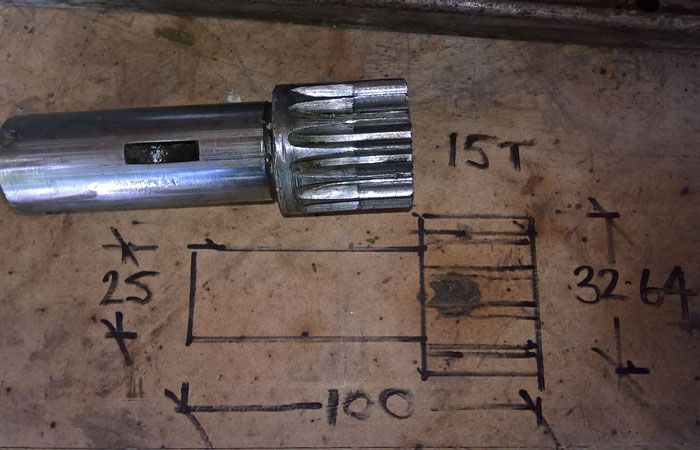
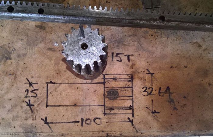
                  So I have a shaft 100mm x 32.64mm dia with 62mm stepped down to 25mm. The gear is 14dp 15 teeth 14.5 pressure angle.

                  Do I have any chance of buying this off the shelf or is it a case of having a go at making it myself (which I'm quite keen to do but at the moment I haven't got a dividing head and they seem to be very expensive).

                  Any help much appreciated,

                  Philip.

                  #411665
                  Howard Lewis
                  Participant
                    @howardlewis46836

                    When I had a smash up on my lathe, I found that buying a cutter and making my own gear worked out at less than half the cost of replacement parts. And the shaft was Silver Steel rather vthan the original rather soft and bendy steel.

                    FWIW, buy a Rotary Table with Dividing Plates (Go for one with as high a ratio as possible, any error will will be reduced by the ratio. Mine is 90:1 rather than the 36:1 that some current offerings provide.

                    You will find other jobs on which to use it.

                    I found, the hard way, that there were a few errors in the chart with my table, so if any doubt, do a check calculation before cutting metal. I wasted three days work, and material before I calculated and realised that the chart was wrong, not me!

                    Howard

                    Edited By Howard Lewis on 30/05/2019 11:08:10

                    #411666
                    Anonymous

                      A picture of the existing part would help. The numbers for the gear parameters don't stack up. The OD of a standard spur gear is the number of teeth plus 2 all divided by the diametral pitch. So we have (15+2)/14 = 1.214", or 30.84mm. Not sure how that fits in the with shaft measurements?

                      Unless you can find a source of proper spares I think it is unlikely you'll be able to buy the part off the shelf. You may be able to buy a suitable gear and fit it to a shaft. It's not difficult to cut a 15 tooth gear, it's 24° per tooth. No need for a dividing head, you could get away with disc marked out and drilled mounted on the end of the shaft. It would help to know what facilities you have available. A pressure angle of 14.5° is most likely, it's an older standard.

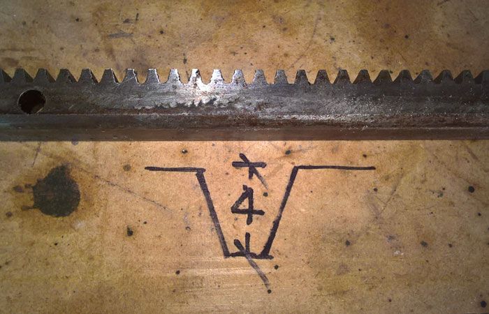
                      Can you measure the depth of the tooth on the rack? It may help to resolve the number issues.

                      Andrew

                      #411682
                      duncan webster 1
                      Participant
                        @duncanwebster1

                        If it's driving a rack it might well be circumferential pitch. Measure over 10 teeth on the rack, if it comes to a sensible number it's CP

                        #411702
                        Philip Sewell
                        Participant
                          @philipsewell33761

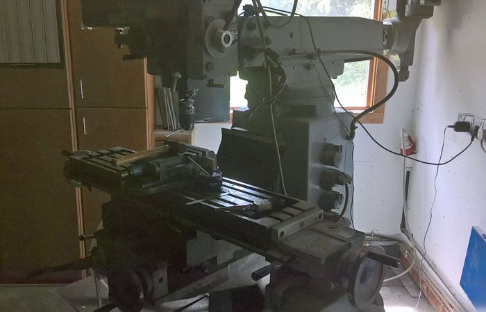
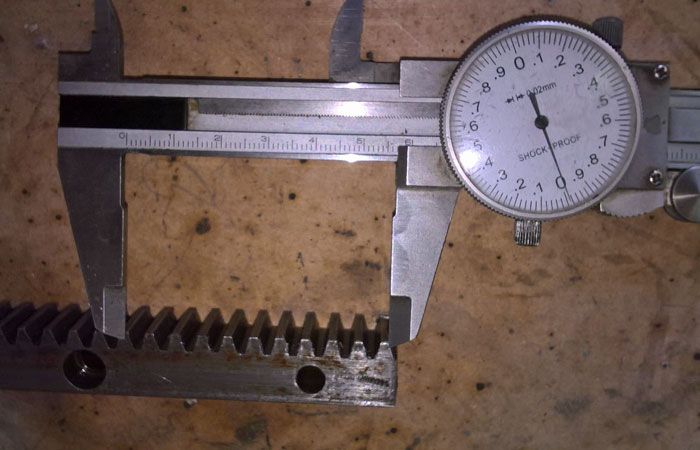
                          forum6.jpgforum4.jpgforum3.jpgforum2.jpgHere are some images and sizes, as you can see I have a mill but no indexing head atm.forum1.jpg

                          #411717
                          Brian Wood
                          Participant
                            @brianwood45127

                            Hello Philip,

                            Working from the picture of the rack, I made that to be 14 DP

                            Regards

                            Brian

                            #411727
                            Anonymous

                              The results for the rack definitely seem to indicate 14DP. If we assume the total tooth depth is 2.157 divided by the DP that gives 0.1541" which is 3.91mm, close to 4mm. it's difficult to tell what the caliper reading is on the rack, and the left hand jaw isn't lined up properly. If we assume 14DP that gives a circular pitch of 0.2244", times 10 gives 2.244" or 57.0mm. That's close to the value from the picture but not exact. I suspect the misplaced left jaw will account for most of the error.

                              Having said that the measured OD for a 14DP 15 tooth pinion simply isn't "correct". It could be a measurement issue, or the pinion is slightly non-standard. With an odd number of teeth it's not easy to measure across the gear teeth. Presumably the quoted OD was measured over the uncut part?

                              The good news is that it would be simple to cut the pinion using an involute cutter. A 14DP with a PA of 14.5° is readily available from RDG, although in my experience their cutters can have the wobbles.

                              The pinion doesn't seem to be that worn, not sure I'd bother replacing it at this stage, if it works.

                              Andrew

                              #411729
                              HOWARDT
                              Participant
                                @howardt

                                Phil could probably shim the rack to mesh properly with the gear, to take out any error on gear size so long as Dp is correct. The rack tooth form looks like a straight full Dp tooth form, not one with differing addendum and dedendum. Easy way to make would be to heat shrink gear onto shaft as gear is going to be the most trouble for a beginner with limited kit.

                                #411740
                                Pete Rimmer
                                Participant
                                  @peterimmer30576

                                  The numbers don't stack up because of the low tooth count of the pinion. It's normal to increase the diameter of low count gears to prevent undercut and make the tooth stronger. According to Machinery's handbook (30th edition, page 2162, table 8) a 14DP 15 tooth pinion should be increased by 0.07569" (or 76 thou). If you subtract that 76 thou from the measured diameter of the pinion in question the numbers work out very close indeed for 14DP (14.06 actually).

                                  #411743
                                  Philip Sewell
                                  Participant
                                    @philipsewell33761

                                    Apologies Andrew the caliper reads 57mm, it is lined up as best as I could but being a tapered edge there's a bit of guess work but it's close (it's the camera angle making it look off position).

                                    The same with the diameter on the gear, it's a bit chewed up so again the measurement might be slightly out, yes I measured the uncut part.

                                    The pinion did work but the teeth are almost at a point. As I have the saddle off the machine I thought it would be a good idea to replace it if I can. Both the cross slide and compound lead screws are very worn. I have replaced the worn screw on the cross slide as it was a standard size, the compound apparently isn't. I was quoted £150 + vat for a one off so will have a go at making one when the lathe is back together.

                                    Great to get advice from people that know, thanks all.

                                    #411781
                                    Philip Sewell
                                    Participant
                                      @philipsewell33761

                                      Last question on this now that we have ascertained the dp. To cut this gear can you confirm this is the involute cutter I need.

                                      14DP number 7

                                      **LINK**

                                      Phil.

                                      #411804
                                      Anonymous
                                        Posted by Philip Sewell on 30/05/2019 21:19:30:

                                        To cut this gear can you confirm this is the involute cutter I need.

                                        14DP number 7

                                        In a word, yes. But I'm not sure it's that simple? Thanks to Pete for pointing out the need to increase the OD to alleviate the need for undercutting. What I don't understand is how you cut the gear. If one uses a standard involute cutter and cut to the standard tooth depth then the circular pitch will be wrong, and the arc thickness of the tooth and space will be different. Machinery's Handbook is somewhat vague on this matter. Is a special cutter needed or do we just cut deeper with a standard cutter? It would be great if Pete could enlighten us.

                                        Andrew

                                        #411820
                                        Michael Gilligan
                                        Participant
                                          @michaelgilligan61133

                                          The post dated Jan 01 2014 may be of interest … here: **LINK**

                                          http://www.hessmer.org/blog/category/gears/

                                          He's a clever chap !

                                          MichaelG.

                                          #411830
                                          Hopper
                                          Participant
                                            @hopper

                                            Might be easier to buy a 14DP gear, turn the end of the existing gear/shaft unit down to provide a spigot and silver solder the new gear in position. Might even be cheaper than buying a cutter for one job and certainly cheaper than buying a dividing head or rotary table.

                                            You could however get away without a dividing head or rotary table by making up a pedestal to mount on your mill with a spindle in it to hold a chuck on one end and fit the existing gear at the other, used with a spring-loaded plunger to index your new gear off the teeth of the old gear. Lot of mucking around to make one gear though. But a useful project. Done right, change gears off your lathe can then be used to index other jobs in future. A 24 tooth gear will allow you to index most commonly used divisions, such as 2, 3, 4, 6, 8 and 12.

                                            #411837
                                            Pete Rimmer
                                            Participant
                                              @peterimmer30576
                                              Posted by Andrew Johnston on 30/05/2019 22:31:12:

                                              Posted by Philip Sewell on 30/05/2019 21:19:30:

                                              To cut this gear can you confirm this is the involute cutter I need.

                                              14DP number 7

                                              In a word, yes. But I'm not sure it's that simple? Thanks to Pete for pointing out the need to increase the OD to alleviate the need for undercutting. What I don't understand is how you cut the gear. If one uses a standard involute cutter and cut to the standard tooth depth then the circular pitch will be wrong, and the arc thickness of the tooth and space will be different. Machinery's Handbook is somewhat vague on this matter. Is a special cutter needed or do we just cut deeper with a standard cutter? It would be great if Pete could enlighten us.

                                              Andrew

                                              I'm just an enthusiastic amateur so don't ever take my word as gospel, but I agree with Andrew. The long-addendum profile would be correctly generated if you were hobbing, but not if you are cutting with a single-tooth cutter since the shape is so far departed from the cutter's form. For a small pinion like that I'd grind a form tool from HSS and fly cut them I think, maybe gashing them out with a slitting saw first.

                                              If I weren't so busy I'd have a go at hobbing a new pinion gear for you Philip.

                                              #411838
                                              DC31k
                                              Participant
                                                @dc31k

                                                To the OP. It looks like only the inboard side of the pinion is worn. Use the existing teeth as a pattern, File out the incomplete teeth on the outboard end, cut it off, rotate 180 degrees and glue it back on.

                                                Given that your lathe was made to imperial dimensions, it might be wise to invest in a set of dial calipers of the same language.

                                                #411841
                                                DC31k
                                                Participant
                                                  @dc31k
                                                  Posted by Pete Rimmer on 31/05/2019 06:40:30:

                                                  I'm just an enthusiastic amateur so don't ever take my word as gospel, but I agree with Andrew. The long-addendum profile would be correctly generated if you were hobbing, but not if you are cutting with a single-tooth cutter since the shape is so far departed from the cutter's form

                                                  I think you are correct. In everything I have read concerning addendum shift to prevent undercutting, it is always mentioned in conjunction with GENERATING methods. Indeed, the undercut is produced precisely because of the generating action.

                                                  I would be very interested to explore the concept of doing addendum shift with formed cutters. I need an 18t 14DP 14.5 PA gear but the centre hole required is a bit big, so want to try cutting 18t on a 20t blank. Perhaps one has to do something akin to cutting bevels with B&S cutters and shift the blank between passes.

                                                  The shifted profile gears JS used to post pictures of were hobbed. KG Stock Gears of Japan has some good information online.

                                                  #411979
                                                  Philip Sewell
                                                  Participant
                                                    @philipsewell33761

                                                    Thanks for all the input, I've got various options to think about. It seems that a 14 DP number 7 isn't going to work though. Fair comment about an imperial caliper, I've grown up on metric so not very comfortable with imperial and tend to convert if I can. I put a cheap dro on the cross slide of the lathe so I can work in mm, I'm intending on putting a proper one on the lathe when it's back together. Same issues with the mill which is also imperial, I have put a 3 axis dro on that which was well worth it.

                                                    Phil.

                                                    #411984
                                                    Anonymous

                                                      Thanks to those that replied about how to cut the gear. It sort of makes sense now thinking about generating methods rather than involute cutters. Most of the relevant pages in Machinery's Handbook talk about using hobs. There's much to learn.

                                                      For the OP I would think the best option is from Pete. Grind a single point tool to fit the tooth space on the unworn part of the pinion and make a note of the depth of cut. Then it should be simple to cut the pinion one tooth at a time.

                                                      Andrew

                                                    Viewing 25 posts - 1 through 25 (of 46 total)
                                                    • Please log in to reply to this topic. Registering is free and easy using the links on the menu at the top of this page.

                                                    Advert

                                                    Latest Replies

                                                    Home Forums Beginners questions Topics

                                                    Viewing 25 topics - 1 through 25 (of 25 total)
                                                    Viewing 25 topics - 1 through 25 (of 25 total)

                                                    View full reply list.

                                                    Advert

                                                    Newsletter Sign-up