Help Wire 3 Phase 2 Speed Motor

Advert

Help Wire 3 Phase 2 Speed Motor

Home Forums Electronics in the Workshop Help Wire 3 Phase 2 Speed Motor

  • This topic has 21 replies, 12 voices, and was last updated 19 May 2025 at 22:27 by duncan webster 1.
Viewing 22 posts - 1 through 22 (of 22 total)
  • Author
    Posts
  • #797394
    Allan Day
    Participant
      @allanday33071

      I have a Weiler Matador lathe with a 2 speed 3 phase motor (Dahlander.) I want to run the motor on single phase 240V 50Hz.

      I want a VFD to supply the power to the high speed windings in the motor. Pictures below of the motor connection box, connection box label & the motor information plate.

      Conection block 1

      Motor Information Plate

      Connection box label

      How do I wire the VFD into the motor connection box & configure the 6 terminals in the connection box?


      Would I be better off buying a new 3 phase 2.5Kw motor instead of using the original motor? I would like to use the origional motor.


      Is a 3Kw output VFD adequate for the task?


      Thanks for your help,


      Allan

      Advert
      #797408
      DC31k
      Participant
        @dc31k

        An option with least faff but possibly more financial implications is to buy a VFD that takes 230v single phase input and gives 415v three phase output.

        These are available (very expensive) from Drives Direct, from JFK Electrical in Ireland and from far East suppliers. The generic name in the past has been XSY AT4. See this past thread:

        VFD. XSY AT4 220v 1phase to 380v 3phase advice sort

        You would need to have some procedure such that the speed could not be changed while the output from the VFD is active*. That could be as simple as a flap over the speed change switch that cuts the VFD output when it is opened.

        * perhaps  a more general version of this comment is that it is frowned upon for there to be any switching from whatsoever a source downstream of the VFD while its output is active.

        #797413
        Clive Brown 1
        Participant
          @clivebrown1

          Drives Direct offer a 3hp 415v drive on eBay, but it’s just shy of £900. I think I’d consider a new motor. Do you want the variable speed of a VFD? If not, a single phase motor would be £300 at most.

          https://www.ebay.co.uk/itm/383777994422

          #797430
          noel shelley
          Participant
            @noelshelley55608

            Unless your set on having 3Ph and the original motor I would keep your eyes open for a 2.2Kw 220V single phase motor. They are bigger than a 3Ph unit and do turn up at sensible prices. Saw tables use them as do better pressure washers Etc. Over the years I got my hands on 3 for free. Your looking for a 2 pole 2800rpm motor.

            PLAN B Whilst every body goes for 240v inverters it might be considering a converter to 415v (one name is Transwave )then all the control gear Etc should work as it was designed to. Where abouts are you ? Noel.

            #797469
            SillyOldDuffer
            Moderator
              @sillyoldduffer

              Allan’s lathe is fitted with a specially wound 3-phase motor where 2-speed operation is achieved by switching the windings.  It isn’t a bog-standard 3-phase motor, and it’s not simply a star-delta / 200,400V problem.  The motor plate describes it as a delta/wye wye, not a delta/wye.

              Reasonably good description of Mr Dahlander’s genius here.   In early days of electricity it proved fairly easy to speed control DC motors, but DC power is hard to distribute efficiently.   AC solves the distribution problem, but AC motors proved  very difficult, and speed controlling them was initially thought to be impossible. Tesla’s breakthrough was extended by others, notably Heimholz and Dahlander.   Unfortunately, speed control remained elusive because at the time there was no practical way of altering frequency.   So, AC machines requiring speed control jump backwards through hoops to get it – gears, belts, and more complex forms of mechanical speed converter.  Maybe a massive mercury arc rectifier so a DC motor can be used.   Dahlander alleviated the problem with his 2-speed AC motor; they’re only found in high-end kit because of cost. The control wiring is somewhat complicated too:

              2spd3ph


              Although 380Vac can be provided by an inexpensive Far Eastern VFD (example), that’s the least of the problems.  Affordable VFDs have two significant limitations, both breached by a Dahlender 2-speed motor:

              • As the inductance of the windings matters, VFD outputs are tuned to a single winding set.  Connecting the output to a different set of windings is going off-piste, results undefined, and it might damage the motor and/or the VFD.  RED ALERT: the Dahlander has a pair of 3-phase windings.
              • Disconnecting a VFD output whilst delivering power is a no-no.  The problem is that the windings can behave like a car-ignition coil, generating many thousands of volts.   The spikes can easily destroy the electronics or wreck the motor by puncturing the insulation deep inside the windings.   RED ALERT: the Dahlander changes speed by switching live phases, see contactors K1, K2 and K3 above.   3P also breaks the rule.

              Options:

              • Pay for a 3-phase supply.  (Worth asking, don’t be surprised by a massive quote or outright refusal.)
              • Buy a VFD that allows switching.   (Expensive!  Industrial supplier.  Price on Application,)
              • Install a rotary converter. (More affordable, starting at about £1500.  Hard to find 400V.)
              • Design an ordinary VFD solution that doesn’t break the rules.   (Hard!  Two VFDs maybe? Skilled work.)
              • Change the motor.

              I’d change the motor; Dahlender 2-speed was a good option before VFDs, now they’re an expensive embarrassment. I doubt anyone would specify one in a new design.  Might sell for good money on ebay too, anyone who has to replace one is likely to be desperate!

              Several motor choices:

              • Single-phase.  “Good enough”  rather than good!   Poor start torque, vibration, and forget speed control.  Big single-phase motors are more trouble than small ones.  I think a Weiler deserves better!
              • DC motor.  Good speed control and torque but the electronics above a kW become interesting.   Good choice for small machine tools, less so for big ones.  And the brushes wear out!
              • 3-phase with VFD.   Lots of problems go away.  Smooth, easy speed control, many off-the-shelf solutions including packages with instructions and support.  Plenty of advice on the forum and elsewhere.  Mass-produced and affordable.   VFD speed control of a single motor is simpler than a Dahlender.
              • Brushless DC with controller.   These are gradually pushing 3-phase motors aside.  Similar to 3-phase with noticeably superior performance across the board, and they are more efficient.   Becoming mainstream.  Not checked the practicalities recently, but costs are dropping, instructions getting simpler, and packages are available.    Many report good results by adapting Chinese industrial sewing machine motor/controller combinations, which are very affordable.   Bit small for a Weiler – up to about 1.5kW,  I believe.

              Though 3-phase with VFD looks good in theory, I’d have a good hard look at the lathe’s drive train.   Judging by the excellent lathes.co.uk, this is elaborate (remember jumping through hoops backwards!):

              Buyers of both Matador and Condor were offered a choice of two drive systems, the Type W and Type VS. Intended for use by toolmakers, the Type W used a mechanically operated, infinitely variable-speed mechanism that, with a 7 : 1 drive ratio and fitted with a 2-speed, 1 – 2 h.p. motor, gave stepless spindle speed changes (on 50 Hz) from 28 to 350 r.p.m. in backgear and from 160 to 2000 r.p.m. in direct drive. The Type W is easily recognised by the large drum control wheel fitted to the front face of the strand immediately below the headstock. The Type VS, intended to be more efficient for general work and production processes, was equipped with an interesting oil-bath-lubricated, pre-selector gearbox that, when driven by the standard-fit single-speed 3 h.p. motor, gave spindle speeds from 30 to 620 r.p.m. in backgear and 170 to 3550 r.p.m in direct drive.

              The Dahlander motor is part of a more complex system.    If the motor is replaced, the need for a complex mechanical drive train diminishes.  With luck electronic and mechanical speed control provide the best of both worlds – I believe the mechanical system is usually set to a compromise position and rarely moved. It isn’t how the lathe was designed to work.  Or the other way round, the VFD simply switches between two fixed speeds.  I doubt leaving the mechanical system in a fixed position would be a problem, but it’s uncharted territory for me.

              I’d love to chat with a Myford TriLeva owner who has fitted a VFD.  Does he still move the levers, or does the VFD make them redundant?

              Dave

              #798150
              Allan Day
              Participant
                @allanday33071

                Thanks to you all for your replies, they are appreciated.

                I have been speaking to an engineer who has suggested I could use to original Dahlander motor by implementing a few modifications explained in the following.

                “U V W are the 3 coils in the motor wit A being one end B the other.

                First configure the motor to permanent star by linking Ub and Vb and Wb using a copper strip. The linked B are your (neutral) and the other ends your L1 (Brown) L2 (grey) & L3 (black)

                Your VSD will have an AC in and 3 phase out connect to motor. Swap 2 wires to reverse motor direction”

                Please reply with your thoughts.

                Regards,

                Allan.


                PS I am in Australia

                #798181
                DC31k
                Participant
                  @dc31k
                  On Allan Day Said:

                  Please reply with your thoughts

                  Your engineer is speaking as a true engineer. What s/he has said is not untrue, but is completely unhelpful to your situation.

                  Sure you can re-wire the motor into permanent star, effectively making it single speed, but it will then only operate from 415v 3 phase input.

                  The only way you can get that from a VFD is to buy one that outputs 415v three phase. The most common 415v 3 phase output VFDs also require 415v 3 phase input.

                  Hence, the statement “your VSD will have an AC in” is trite.

                  A VFD that takes 230v single phase input and outputs 415v three phase is a rarer item. As you are in Australia, either you need to find an importer of the far Eastern ones (akin to JFK or Drive Direct in the UK), who of commercial necessity will have some quality level or you buy direct from China via eBay, Amazon, etc.) and take a risk on the quality.

                  Similarly, while the ‘swap any two wires’ is not wrong, it is never something you would do either physically or via a mechanical switch in conjunction with a VFD.

                  So give the engineer 10 out of 10 for engineering but one out of ten for actual practical help.

                  #798189
                  Gerard O’Toole
                  Participant
                    @gerardotoole60348

                    I believe I have a similar setup on my Deckel FP1 mill. i.e. Dahlander wiring. It certainly has two separate sets of winding for low speed and high speed. And i fitted a VFD wired to the high speed set only.

                    I am no electrical expert and relied totally on the supplier of the VFD. Firstly I had to by-pass all low/high speed switches on the mill and wire the VFD directly to the motor. The VFD only outputs 240 V and the motor required 380 V for full power/speed. I was advised by the VFD supplier to run the VFD at at a lower maximum frequency in order to run at 240V. Mine is set to a maximum of 31.5 Hz. (50 Hz / (380/240)) . This of course results in the maximum speed of the mill being reduced by the same ratio, not something that has limited my hobby use in any way. Speed is usually selected by the gearbox with the VFD being used to slow speeds further as needed.

                    I have posted about this before here and was told this reduction in frequency was totally unnecessary. As I say I am no electrical expert , far from it, but the VFD and Mill are working happily now for ten years or more.

                    The Inverter is a Bosch Rexroth EFC3600 2.2kW 230V 1ph to 3ph – AC Inverter supplied by Inverter Drive Supermarket, but I am sure any suitably sized inverter would do. I have various settings and wiring diagrams sent to me at the time by the supplier if they could be of any help.


                    #798193
                    noel shelley
                    Participant
                      @noelshelley55608

                      So a motor of the Dahlander type will not work on a converter, 240v to 415v ? eg a Transwave converter be it static or rotary. I know you will not have variable speed but you have 2 speeds.

                      If money is no object it is a simple problem, otherwise it’s a case of whats the budget, what has the OP got lying around, and what knowledge and equipment they have along with how much time is available.

                      My Transwave was too small, I needed 17Kva so I built a 20Kva 3Ph diesel genny Not an option many could or would want to take, but it worked for me and cost less than £500. I now have REAL 3Ph in a village where there is NO 3Ph. Noel.

                      #798196
                      SillyOldDuffer
                      Moderator
                        @sillyoldduffer
                        On Allan Day Said:

                        I have been speaking to an engineer who has suggested I could use to original Dahlander motor by implementing a few modifications explained in the following.

                        “U V W are the 3 coils in the motor wit A being one end B the other.

                        First configure the motor to permanent star by linking Ub and Vb and Wb using a copper strip. The linked B are your (neutral) and the other ends your L1 (Brown) L2 (grey) & L3 (black)

                        Your VSD will have an AC in and 3 phase out connect to motor. Swap 2 wires to reverse motor direction”

                        Please reply with your thoughts.

                        … 


                        In principle, yes.   But the devil is in the detail, and the description is basic. I’m also a bit worried about “U V W are the 3 coils in the motor wit A being one end B the other.”    That describes an ordinary 3-phase motor, but this is a Dahlander, which I believe has 6 windings, not 3.  The words are ambiguous, “not wrong”, but might be hiding a misunderstanding?

                        Sorry it’s in German, but next diagram shows how the 6 windings in a Dahlander can be connected, assuming all the ends are available in the terminal box.  More to think about than ordinary 3-phase!

                        dahlander

                        For the avoidance of doubt, can you share a circuit diagram showing exactly how your engineer says the motor will be connected?   From LN to the VFD and from VFD to motor.

                        Also, equally important, what should be disconnected inside the lathe?  The existing electrical switches and contactors will be set up for dual-speed, wrong if a VFD and strapped motor are used.  I find control switching harder to understand than connecting the motor.  For example, the diagram in my #797469 shows an overload trip and the contactors used to change speed, but not how the contactors are wired to the front-panel switches and any safety interlocks.  It too is a statement of principle, not an actual diagram.   Don’t panic, disconnecting redundant circuitry is easier than adding new.  May be as simple as unhooking the existing stuff from the power input and the motor, and telling the operator to ignore the old front-panel switches.   But be careful about disconnecting safety interlocks – they exist to stop stupid accidents.   What does your engineer suggest?

                        Dave


                        #798203
                        Julie Ann
                        Participant
                          @julieann

                          Ah, SoD has beaten me to it; his original link about the Dahlander connection was rather muddled and seems to equate changes of impedance to change of speed, which is nonsense.

                          As shown in SoD’s later post the Dahlander system is beautifully simple and consists of six coils. With the coils run in delta, with pairs of coils in series, you get 2n poles = low speed. By shorting the midpoint of each leg of two coils in delta (K2 in the original link by SoD) the arrangement is changed to two star connections in parallel for n poles = high speed.

                          My horizontal mill has a similar arrangement, it has a low and high speed. In high speed the motor is 5hp, in low speed it is 4hp so not simply pole switching, or the power would be 2.5hp in low speed. There are two switches that need to be moved to switch from low to high range. One is on the control panel and the other, clearly electrical, is below the gearbox selector. The second switch is shown here:

                          Photo 3 - Speed Change Arrangement

                          Changing of both switches is done with the motor stopped.

                          On the other hand the two speed motor on my repetition lathe has two electrical switches on the headstock for changing speed range and direction. The speed change is simply pole switching as power in low range is half that of high range. In contrast to the mill the switches can be thrown when the lathe is running. So one can go from low speed and forward direction to high speed and reverse direction just my moving two switches; no need to stop the motor. The motor does clunk a bit, but is designed for instant reverse/speed change as befits a production machine. An operator on piecework wouldn’t be happy if they had to stop the motor each time something needed changing!

                          Both of my machines run on true 3-phase, an upgrade I did soon after moving into my property. Part of the excuse was that the original supply was only 60A and had a wind yer own fuses box. So it needed upgrading anyway. It cost me £2k to have 3-phase installed, albeit that was 20 years ago. I was told by a friend in the building trade that half of the cost was due to the electricity network company having to dig up the road to get to the 3-phase supply buried on the other side of the road. Apparently they have to cover any costs due to poor workmanship on the road excavation for a year.

                          For the OP the best solution is a 3-phase supply, allowing the lathe to be used properly. Failing that probably best to change the motor.

                          Julie

                          #798222
                          Nicholas Farr
                          Participant
                            @nicholasfarr14254

                            Hi, this schematic might be clearer to understand, as it doesn’t look too cluttered to me.

                            Dahlanders 

                            Web page

                            Regards Nick.

                            #798239
                            Robert Atkinson 2
                            Participant
                              @robertatkinson2

                              Julie Ann beat me to it.
                              Unfortunatly there is no way to wire this motor for 240V Delta as it is. However if all the winding ends are brought out to the terminal block it could be re-wired.
                              You need to look at the back of the terminal block. If there are two wires on each terminal it can be rewired as Double Delta. This allows you to use a low cost 240V output VFD. Ideally wire for lowspeed and use the VFD to double the frequency and speed.
                              If there is only one wire on 3 (or more) terminals you need to dig further and see if the ends of each winding can be accessed. If not you would need a 240V in 415V out VFD.

                              Robert.

                              #798241
                              Peter Bell
                              Participant
                                @peterbell11509


                                Great shame the 240V in 415V out VFD are always  so expensive, not sure why as I the ones I’ve been involved with just use a voltage doubler circuit to give 650v dc to feed the inverter HT rail from the 240v ac for what looks like a standard 415v VFD in a bigger box.

                                I also come across an example that used the internal reservoir capacitors as part of the voltage doubler,  perhaps I’ve missed something?

                                #798247
                                Diogenes
                                Participant
                                  @diogenes

                                  Project Machinery have a used 3.7Kw Transwave.

                                  #798250
                                  Robert Atkinson 2
                                  Participant
                                    @robertatkinson2
                                    On Peter Bell Said:


                                    Great shame the 240V in 415V out VFD are always  so expensive, not sure why as I the ones I’ve been involved with just use a voltage doubler circuit to give 650v dc to feed the inverter HT rail from the 240v ac for what looks like a standard 415v VFD in a bigger box.

                                    I also come across an example that used the internal reservoir capacitors as part of the voltage doubler,  perhaps I’ve missed something?

                                    Supply and demand mostly.
                                    You could take a 415 input VFD and feed the appropriate DC power into the DC link bus. About 550V is typical. 240V doubled is about 670V so a bit high. Off load this may trip the over-voltage protection on the VFD. Another issue at the OP’s size is the poor power factor and amount of harmonic distortion caused by the doubler.

                                    Robert.

                                    #798255
                                    DC31k
                                    Participant
                                      @dc31k
                                      On Peter Bell Said:


                                      Great shame the 240V in 415V out VFD are always so expensive…

                                      As above, it is supply and demand. Who actually buys the items?

                                      You may also need to be more precise with your words. You can buy a 230v in 415v out claimed 4kW one from Amazon for £150.

                                      The expense comes from the allocation of risk – if you assume the risk, you save money. If you wish the supplier to take on the requirements of UK consumer legislation, you pay more.

                                      #798678
                                      Allan Day
                                      Participant
                                        @allanday33071

                                        <p style=”text-align: left;”
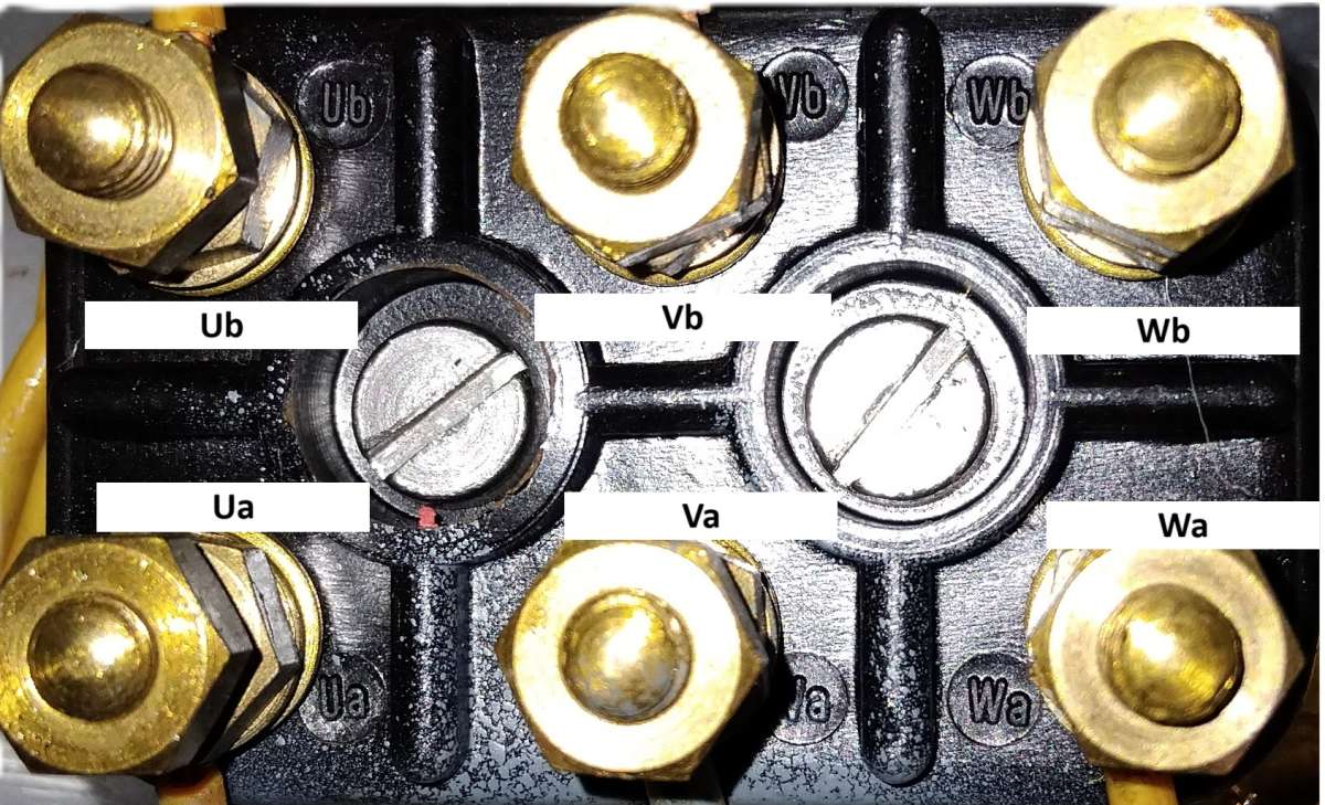
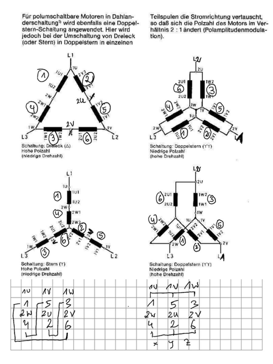
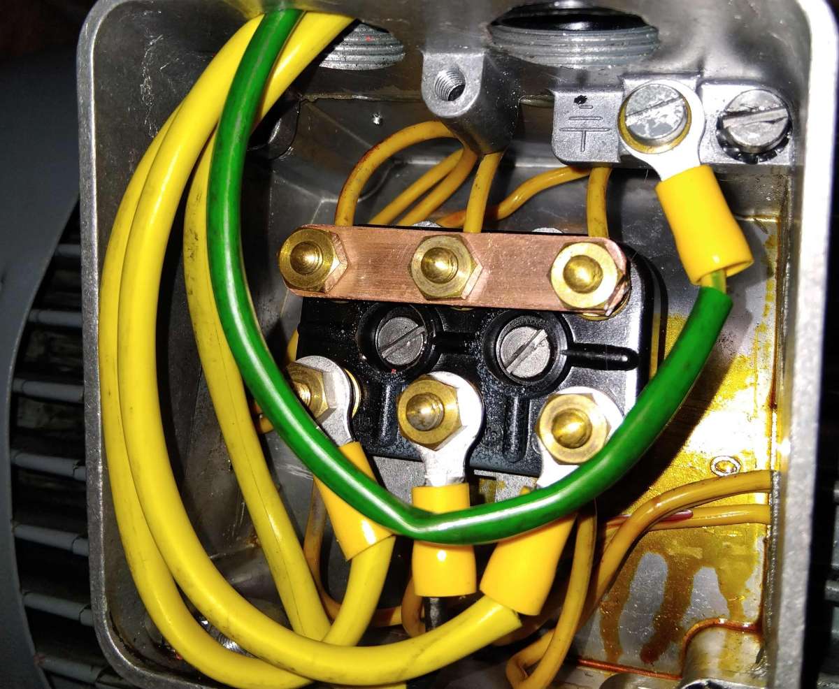
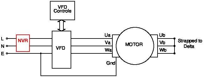
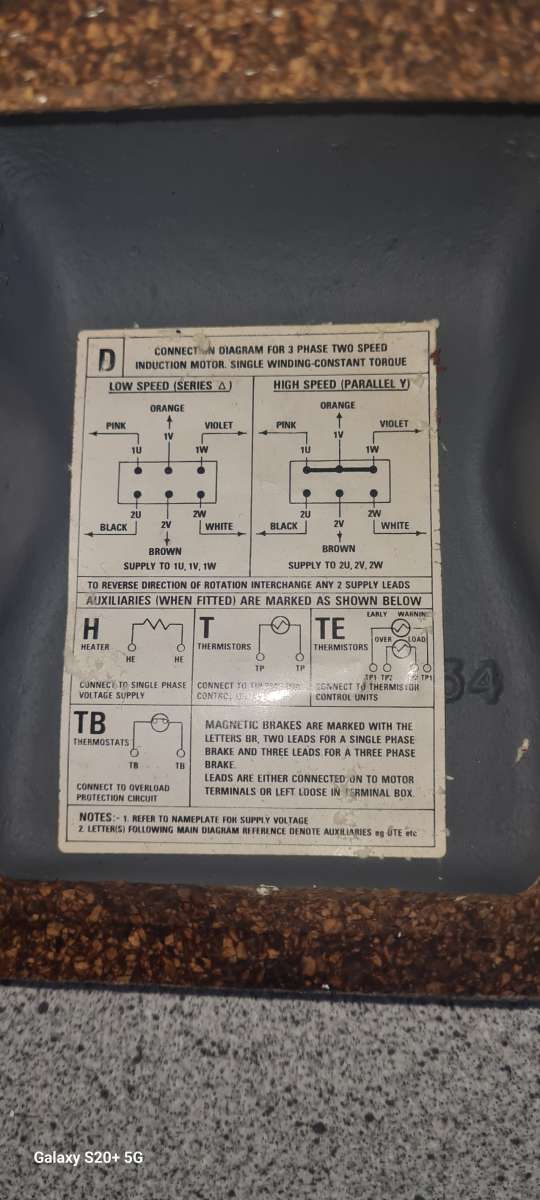
>Thank you all for your replies, again!</p>
                                        The picture of the connection box below is as the engineer I have been speaking to says.

                                        The 3 yellow & earth wires go directly to the VFD.

                                        NO switching between the motor & VFD.

                                        The VFD will be used to switch the motor on off (high speed ONLY) & speed control.

                                        The original switch gear has been removed from the machine.

                                        Gerard O’Toole’s post is what I am aiming for.

                                        PS. The wiring in the picture is just for the picture, it is not connected to anything.

                                        Regards,

                                        Allan


                                        Con Box 2

                                        #798729
                                        SillyOldDuffer
                                        Moderator
                                          @sillyoldduffer

                                          Allan, words and photos make work at this end compared with a circuit diagram.   And they risk helpers making mistakes whilst reverse engineering them.   However, if this is what you’re doing, the motor should run as expected:

                                          dahlander

                                          Note the “No Volt Release” switch shown in red.  Recommended for emergency power off, and NVR prevents accidents when power comes on unexpectedly after a power-cut.

                                          Also, lacking detail is the “VFD Controls” box.  The controls handle ON/OFF, Forward/Reverse, Speed, and the Safety Interlocks.  Wiring this can be tricky – read the manual, and ask again if necessary.   Most VFDs are components, i.e. mounted inside a protective box, and it’s calculator-like interface is intended for set-up only, not routine operation.  Instead, the VFD is worked from a box located convenient to the operator, and it’s handy to fit a tachometer showing spindle speed.

                                          Dave


                                          #798745
                                          duncan webster 1
                                          Participant
                                            @duncanwebster1

                                            If wired up correctly the vfd will provide the nvr function

                                            #798836
                                            Allan Day
                                            Participant
                                              @allanday33071

                                              Dave, Thanks for your replies.

                                              Your diagram, less the NVR, is what I have planed for my lathe.

                                              The VFD switching controls will be remote, via the lathes apron lever (how it was originally controlled, forward / reverse) & a potentiometer mounted remotely from VFD. There will be a breaker between switchboard mains supply & VFD.


                                              Regards,


                                              Allan

                                              #798838
                                              duncan webster 1
                                              Participant
                                                @duncanwebster1

                                                If the apron lever is just a fwd/off/rev switch then my previous email doesn’t apply and an NVR would be a good idea.

                                              Viewing 22 posts - 1 through 22 (of 22 total)
                                              • Please log in to reply to this topic. Registering is free and easy using the links on the menu at the top of this page.

                                              Advert

                                              Latest Replies

                                              Viewing 25 topics - 1 through 25 (of 25 total)
                                              Viewing 25 topics - 1 through 25 (of 25 total)

                                              View full reply list.

                                              Advert

                                              Newsletter Sign-up