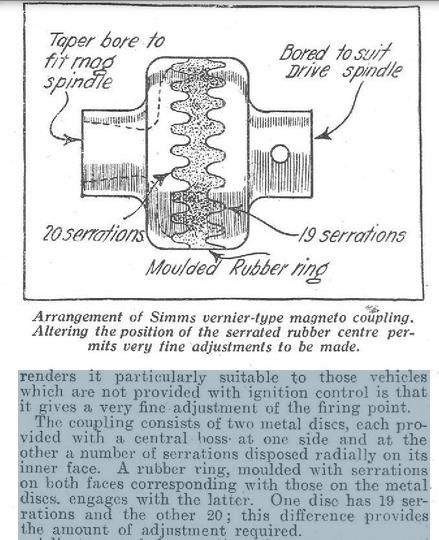
Strictly speaking, a Simms vernier coupling should have round topped teeth, rather like a knuckle thread, but probably gear teeth will suffice, since there should be no relative movement, and the object is to provide a fine angular adjustment.
You will be constrained by the diameter of the original coupling. The number of teeth required on each part may determine the DP that you can use
The space available for the completed coupling will also be a factor in determining the DP
Dimensions of the existing components, if avaliable, should provide some guidance.
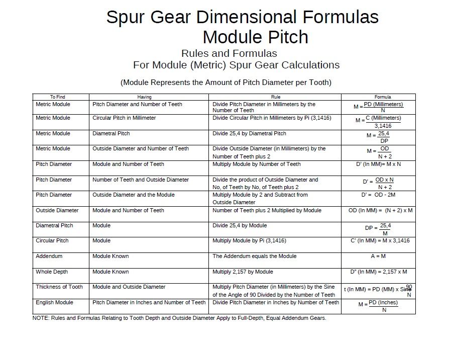
The finer the the DP the shallower will be the depth of each tooth, the more teeth will be cut onto the each part of the coupling. A 20 DP tooth will be 0.108" deep, whilst a 40 DP tooth will be 0.054" deep, leaving the space for the body of each part of the coupling.
Presumably, the Driving and Driven parts of the coupling will either have a keyway in the bore, or a tapered bore (Possibly a standard numerical taper?  .
.
The DP will help to choose the depth of the tooth, and so the overall length of the coupling.
Total length of coupling will be: (Overall thickness of Driving part + Overall thickness of Centre coupling + Overall length of Driven part ) This will be determined by the space between the Magneto and the the Timing Case
The counterbores on each of the three pieces will provide space for the nut retaining the Driving and Driven parts to their shafts
The finer the tooth pitch (Diametral Pitch) the finer the adjustment that you will have. and the shorter the length of the complete coupling,
SO, picking numbers out of the air, purely as an example..
The idea is to have one half with,say, 20T and the other with 19T. So that an advance of 18 degrees (1T on the 20T ) is counteracted by retarding the other half by 1T ( to give a retard of 18.947 degree, which effectively retards by 0.947 degrees, when the two parts re engage Or vice versa, to give a fine adjustment.
Since the gear teeth will not be rotating against each other, it would seem allowable to cut the teeth across the face of the components, rather like a flat bevel gear (if you can describe the parts such a thing )
Presumably the technique is to cut three sets of teeth. .In each case the teeth will have to be cut into a face that has been counterbored to a depth, at least, if not slightly deeper than the teeth.
The Driver will have 20T, The Centre coupling will have 20T on one side, and 19T on the other, so may well need to have one set cut whilst on a sacrificial arbor.
The Driven component will of the coupling will have 19T on the face.
It is possible that the complete assembly will,need to be checked for length against the space available, and the rear faces of Driver and / or Driven components be faced to reduce to the required length.
HTH
Howard
martyn nutland.


 .
. 


