Ford Quadricycle Engine

Advert

Ford Quadricycle Engine

Home Forums Help and Assistance! (Offered or Wanted) Ford Quadricycle Engine

Viewing 25 posts - 1 through 25 (of 29 total)
  • Author
    Posts
  • #33768
    Brian H
    Participant
      @brianh50089
      Advert
      #519119
      Brian H
      Participant
        @brianh50089

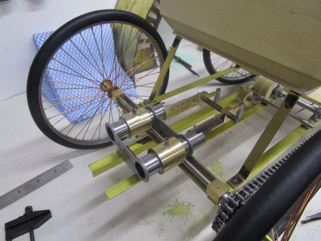
        My 1/4 scale model of Fords 1896 Quadricycle now has the outline of an engine installed.

        I'm hoping to get the engine running but am unsure of the carburettor and ignition.

        The carb I am not too concerned about and will try it to Fords original specification. Would lighter fuel be OK to use? I'm assuming that it may be purer and more volatile than pump petrol.

        More of a problem may be the ignition. The Ford one was a very basic idea but the details are a little hazy and I'm wondering to tackle the ignition.

        Any help much appreciated and I would like to stay as authentic as possible.

        engine installed.jpg

        Brian


        Edited By Brian H on 11/01/2021 15:34:27

        #519126
        Oily Rag
        Participant
          @oilyrag

          Interesting project!

          Having seen the original in the Ford Detroit museum I would have thought they would be able to help with the technical details. On your suggestion of using 'lighter fuel' I would sound a note of caution as lighter fuel is mainly Naptha based and has some serious drawbacks for running an IC engine, one of which is serious oil degradation the other being vapourisation characteristics.

          From a distant memory of this vehicle I believe the carburettor was a surface evaporation type (see http://earlymotor.com/leon/misc/html/surface.htm) and the ignition was a trembler coil system, sometimes referred to as a Ruhmkorff coil (search Wikipedia for this).

          Martin

          #519159
          Brian H
          Participant
            @brianh50089

            Many thanks for your comments Martin. I have a drawing of Fords carb and intend making it as a sale model to suit the Quadricycle. I'll try it on pump petrol. I don't want it to power the car, just to run for at least a few minutes.

            I've just realised that I have a drawing for the ignition system which will give me a starting point, my main worry is the strength of the spark but I usually live in hope with these projects.

            #519166
            Tim Stevens
            Participant
              @timstevens64731

              A trembler coil is a conventional ignition type coil – a steel core on which are wound one thicker winding (the primary), 200 turns or so, and one of much thinner wire and lots more turns (the secondary), but with an extra device. This is the addition of a steel blade at one end which is attracted by the magnetism when the primary coil is energised (connected). The blade is part of the primary circuit, and as it moves towards the core of the coil it opens a switch (just two contacts called 'points'] and the current and magnetism stop, releasing the blade. This closes the contacts again, and on and off it all goes, usually making a buzzing noise, and a high voltage (for sparks) is generated within the secondary winding. This coil needs to be connected to the sparking plug, so the fuel is ignited. There must also be another switch in the system, to set the sparking in progress at the right time (as the piston finishes the compression stroke), and to disconnect the whole thing soon after (to avoid overheating the coil, and flattening the battery). This was often a wipe contact rotating with the exhaust cam – just a brass blade and a brass section in an insulated strip. This is the contact which is set to time the engine.

              But … you might find that the car did not have such a system, but instead used an earlier version. This has a similar type of battery and coil, but with only a primary winding, and no vibrating blade. Instead, there is a contact in the cylinder worked by a different version of sparking plug, operated by a rod worked by a separate cam on the exhaust camshaft. If you need more details of this system, come back to me.

              Funny things, very old cars. Sometimes they are so different that they are generally not understood, even by their owners. And sometimes, especially by their owners.

              Regards, Tim

              Edited By Tim Stevens on 11/01/2021 18:20:44

              Edited By Tim Stevens on 11/01/2021 18:21:10

              #519169
              JasonB
              Moderator
                @jasonb

                I tend to run my IC engine models on Colmans fuel which you can get from camping and outdoor shops, the Americans call it "white gas". it has a slightly lower octane than pump petrol but does not stink out teh workshop or house.

                However seeing teh comment about a vapour carb then the lack of smell ofte Colemans is it's downfall so if you do go done that route then petrol will be your best bet I've a couple of engine swith vapour carbs and they run well with teh added bonus on non flooding.

                As for ignition I would have suggested S/S as a source for a modern electronic buzz coil but he is retiring. Minimag's buzz coil is not really one as it only gives a single spark, Engineers emporium do them or just the contacts that you can add an ATV coil to and make your own which is quite easy. If you want to hid the ingition in the model then have a look at Jan Ridders "Bloker" iignition which uses a piezo gas lighter that can be actuated by a small reed switch abd is very small, I have the bits but have not made one up yet.

                Edit, Tim is probaly talking about an ignitor in his last paragraph, fiddly to make in the smaller scales but satisfying when they run. I have used an old ballast from a strip light as the coil but they are a bit bulky, Minimag do a nice potted one about the size of a 35mm film canister which I have used on about 3 or 4 engines now.

                Edited By JasonB on 11/01/2021 18:31:14

                #519171
                Brian H
                Participant
                  @brianh50089

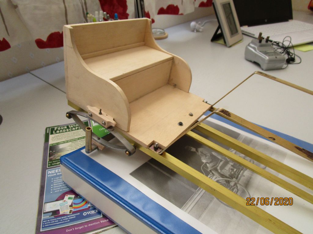
                  Many thanks Tim and Jason, I shall have to compare the details I have with the systems described, Fortunately, the vehicle has a large box at the front which housed the original battery cells so that may be big enough to hide the electrics.

                  Brian

                  img_0288.jpg

                  #519203
                  John Olsen
                  Participant
                    @johnolsen79199

                    PM research sell a trembler coil for use with their Red Wing engine. It may be available from some of the UK sellers of their castings, some of whom I think may advertise on this site, or in the magazine at least. The Model T Ford used the trembler coil system. I'm not sure what the quadricycle used even though I have seen both of them. If I recall correctly, there are two of them, the original one in the Ford museum and a replica in the replica brick shed in Greenfields village.

                    Early infernal combustion engines used all manner of weird ignition systems, some with moving contacts inside the cylinder, which never seemed like a good idea to me.

                    One idea would be to use a modern cdi system, hidden somewhere. Not authentic but very effective.

                    John

                    #519209
                    Tim Stevens
                    Participant
                      @timstevens64731

                      The model T was much later, and used an alternator (yes!) mounted between the flywheel and the clutch. The trembler coils it had were fed with AC, so this has little in common with pre-1900 motors.

                      Please don't take my descriptions as any more than a guide to what might have been fitted, perhaps to help you interpret any pictures diagrams etc from the original period. There is also a possibility that the engine had a magneto, but a very primitive one, with one coil connected directly to a sparking plug of the switched type I described earlier. You need to remember, too, that whatever is fitted now is very likely not to be anything like the original. Early electrics were noted for short lives and failure often involved their complete destruction, sometimes involving the whole vehicle.

                      Unless you are sure that a trembler coil was fitted, AND you wish to replicate the buzzing or clattering noise, I'm sure a more modern coil and battery system (see John Olsen above) will take up less space than any original battery and coil. And work at least as well, and for longer.

                      And regarding fuel, the nearest equivalent to the motor spirit of 1900 would be 'petroleum ether, SG 0.65'. The main characteristic thought useful was that it evaporated readily.

                      Finally, it can help to remember that the pre1905 vehicles which trundle down to Brighton so gloriously each November are not a representative sample. They are mainly vehicles that were so bad that after the first two or three trips their (rich) owners threw them in the back of a barn, where they remained until discovery – prompted by the film Genevieve in many cases. Anything that worked well was driven, and mended, until it failed utterly, by which time there was nothing worth saving, and anyway, there was a war on.

                      Regards, Tim

                      #519220
                      John Olsen
                      Participant
                        @johnolsen79199

                        The Model T is in fact a prime example of early ignition weirdness since it used both DC and AC. There was a battery box with dry cells, used to provide the spark when starting. (But not cranking, which was manual) Because of the trembler system, it was not impossible for the engine to start immediately when the ignition was turned on. This required a fluky situation, a cylinder that happened to be full of mixture from the last run and stopped in just the right position so that when the ignition was turned on, the resulting spark kicked the engine over. I have heard that this could be so startling that the result was that the ignition was immediately turned off again.

                        The other aspect of the vintage vehicles is that they often are valued greatly because they are rare, and often the rarity is because they were no good in the first place. "There were only five ever made and this is the last one in existence." This does not of course apply to vehicles that were never intended to be made in quantity, like racing cars and ultra luxury vehicles.

                        The CDI system I was thinking of is commonly sold for model aircraft applications, it is not much bigger than a box of matches, including the coil inside, and would easily conceal inside a quarter size seat I should think. It will run for a long time from a small battery pack. It uses a small magnet and a hall effect sensor for timing, also easily concealed.

                        John

                        #519225
                        Oily Rag
                        Participant
                          @oilyrag

                          Brian,

                          "my main worry is the strength of the spark …."

                          If you do have problems with the strength of the spark you can utilise a 'sustainer' coil – best example I can give of this system is the Metro 6R4 rally car of 1987 – it causes a lot of people to scratch their heads trying to understand how it works.

                          Due to the odd firing order of 135 – 45 – 45 – 135…… the 6R4 had a secondary full size coil attached in parallel to the 'working' coil, the weird point is that the second coil had the HT chimney blanked off, this secondary coil acted as a reserve for the short duration firing intervals.

                          As for using a CDI system the problem I fore see is the extreme high voltage coupled with an extremely short time duration of the spark. An induction or Hall Effect system gives a lower HT spike but a much longer time duration and low speed engines with low compression and low grade fuel much prefer a long spark duration. The Ruhmkorff coil effectively was what nowadays is a MSD type ignition system (MSD = Multi Spark Device). The MSD being a CDI with multiple sequenced sparking to overcome the short time duration of the CDI spark. MSD's are popular with alcohol fuelled engines due to the poor vapourisation of alcohols.

                          Martin

                          #519236
                          JasonB
                          Moderator
                            @jasonb

                            A Buzz coil does not need to make any noise, the modern electronic CDI based Buzz coils are small and silent so can be hidden easily inside the model.

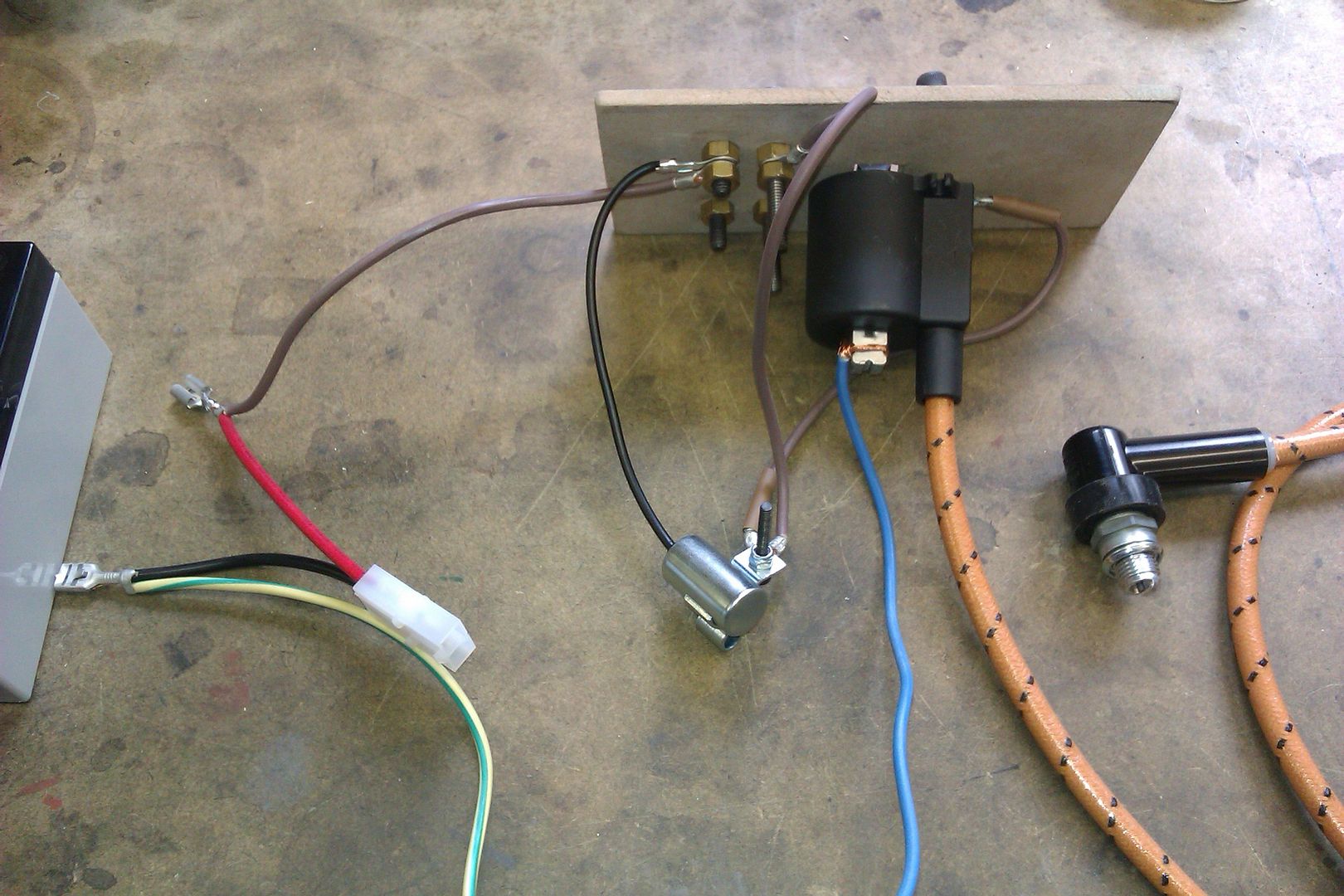
                            S/S Buzz Coil on right of page, I have one of these and two videos of the RMC one which I have reserved when he next makes a batch, compare that to the one made with traditional trembler coil contacts and ATV coil that buzzes away like a good un.

                            The main advantage on these primative engines of a buzz coil is that it sparks over a wider band of the cycle and will ignite the air/fuel mix as it is compresses to the right pressure so you have a lot more leyway over timing, with a single spark you are going to have to fiddle about a lot more to hit the sweet spot. I would still suggest you try make your ignition contacts adjustable so that you can advance and retard the timing which again gives you more adjustment of how the engine fires.

                            As it's a 2- cylinder I think I would opt for separate systems for each plug rather than a distributor, you can get some CDIs with two of the miniature coils again I have an S/S one for my 2-cylinder engines but I don''t think any other suppliers do them.

                            #519241
                            Brian H
                            Participant
                              @brianh50089

                              Many thanks to all for the useful information. I need to sit down and work through the possibilities.

                              Brian

                              #519243
                              JasonB
                              Moderator
                                @jasonb

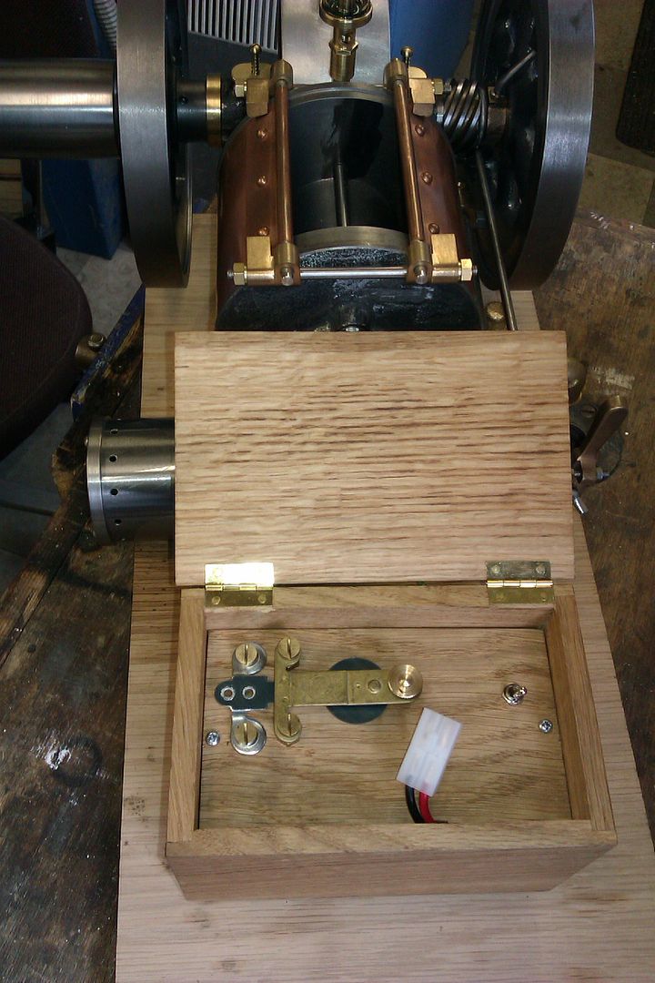
                                This shows the Jan Ridders "Blokker" quite well, not Piezo as I said earlier but similar circuit toe the other CDI types. More details on his site where you can see how small it is so easy to hide two in the model and you can have smaller contacts or reed switch rather than the microswitch he tends to use.

                                #519261
                                Brian H
                                Participant
                                  @brianh50089

                                  Again, many thanks Jason for the info and link to Jan Ridders. Now I can study it and add to my Dutch language learning at the same time!

                                  It will be some time before I'm able to start on the ignition side but I'll post on here with details.

                                  Brian

                                  #519263
                                  JasonB
                                  Moderator
                                    @jasonb

                                    There is a button to click for the English version.

                                    #519275
                                    Brian H
                                    Participant
                                      @brianh50089

                                      Jason, I found the English version button thanks but I am actually learning Dutch as Netherlands is favourite holiday destination (when we get the chance again)

                                      Brian

                                      #519278
                                      Brian H
                                      Participant
                                        @brianh50089

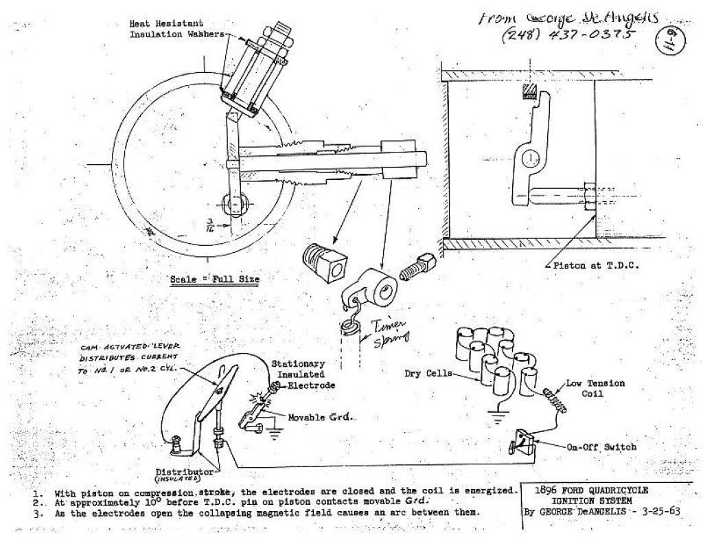
                                        Me again! I've now found the drawing for the original ignition system on the Quadricycle in The Henry Ford Museum.

                                        This was obtained from "The Early Ford Register" who have a full set of drawings and sketches and will make them available to anyone who pays the very modest joining fee.

                                        Brian

                                        6-11b ignition system1024_1.jpg

                                        #519291
                                        JasonB
                                        Moderator
                                          @jasonb

                                          Looks to be a form of what is known as an "ignitor" that is tripped by the piston rather than the more usual cam. I can see that you may get some battery drain and a hot coil as it seems the circuit is "made" for most of the time and only as the rod on the piston breaks the circuit do you get the spark. Most ignitors work by only making the circuit for a short time to energise the coil just before the spark is needed.

                                          Up to you whether you try to model it or simply make a spark plug to look like the insulated electrode.

                                          If making it as an ignitor than something like Corian can be used as the insulation material and a piece of TIG welder electrode silver soldered onto the ends of the two pieces of metal that make contact to save them getting eroded away. Or Hemmingway sell small discs of carbide that will do the same job.


                                          Edited By JasonB on 12/01/2021 12:04:57

                                          #519293
                                          Grindstone Cowboy
                                          Participant
                                            @grindstonecowboy
                                            Posted by John Olsen on 11/01/2021 23:40:06:

                                            …Because of the trembler system, it was not impossible for the engine to start immediately when the ignition was turned on. This required a fluky situation, a cylinder that happened to be full of mixture from the last run and stopped in just the right position so that when the ignition was turned on, the resulting spark kicked the engine over….

                                            Just to digress slightly, I believe that BMW have managed to do this intentionally (and reliably), with the aid of crankshaft position sensors, fuel injection control, etc. so one day we may no longer need starter motors. Or we'll just have electric cars instead…

                                            Rob

                                            #519301
                                            Tim Stevens
                                            Participant
                                              @timstevens64731

                                              Hi – yet again

                                              I have a copy of the ICS reference library volume 24 – … Ignition & Carburettors. very useful for stuff pre 1907.

                                              It refers to a Lodge Igniter, of which the principle was 'the discharge of condensers through the sparking plug'. So far as I can find, this system is the first reference to what we now call CDI. Lodge is the same Lodge whose name was attached to sparking Plugs in the days when we made them in the UK. The text then explains how the spark is useful for 'sweeping away all obstructions, such as oil or soot, that may be in its path. It is therefore extremely useful for ignition purposes, especially for engines running on kerosene, alcohol, or other less volatile fuels.' It seems that the term Ignitor used earlier in this strand refers to the same sort of device.

                                              My reference to a system using only a primary coil (and no condenser) is not the same as an Ignitor (Lodge or otherwise), but a more primitive device relying on breaking an inductive circuit by a contact within the cylinder of the engine. Not very clever, but used in many cars before ww1.

                                              Hoping this helps to clarify … And please note – we had a reference in this forum to the ICE Reference Library about a month ago, recording that the whole series of books was now available to view on line.

                                              Regards, Tim

                                              #519339
                                              Brian H
                                              Participant
                                                @brianh50089

                                                Thanks Tim, yes I remember the piece about ICS and I saved it as a favourite. And thanks for the reference to Lodge etc.

                                                Brian

                                                #519377
                                                Tim Stevens
                                                Participant
                                                  @timstevens64731

                                                  Ignore this if you are already up to speed on the Ford drawing:

                                                  This shows a very primitive (early) version of the final option I suggested it might be. The circle top left is the view down the bore if you take the head off. Top right of this is the insulated 'plug' which produces the spark. It is not clear how this is fixed in the bore, but it needs to be insulated against lots of volts, heatproof against petrol flames, and not able to be blown out by the repeated explosions.

                                                  The screwed fitting at the right – fitted through the bore with a tapered thread (a tradition which was later used for sparking plugs and lasted to the end of the model T in about 1928) – carries a central spindle, on the inside end of which is a lever as shown to the right of the page – and the bar carried by the spindle rests against the projecting electrode of the plug. This connects the plug to earth (chassis) and completes the circuit (we'll come to that). When the piston approaches the head on the compression stroke, a peg on the piston thumps the other end of the bar, and disconnects this earthing connection, causing a spark. The lever is sprung loaded to hold it against the plug (square-head fitting, and timer spring details are shown), so as soon as the piston descends, the connection is once more connected to earth.

                                                  At the bottom of the page a sketch shows a 'distributor' but actually only some bits of it. Somewhere on the engine there is an insulated distributor post carrying a pivoted blade, which is moved to and from by a cam (eg). the end of the blade makes contact alternately with a blade on the sparking plug of each cylinder, switching on the current to that cylinder so that there is current flowing as the piston starts to rise on the compression stroke for that cylinder. When the current has stopped and the spark has jumped, the pivoted blade is flicked across to the other cylinder ready for its piston to start up the bore.

                                                  The timing of the piston opening the circuit is fixed by the geometry of the piston peg and the timer blade inside the cylinder. This is not clever, as it cannot easily be be adjusted from outside, and to start with you won't know what timing to use. Too late and you will make lots of heat but not much power; too early and you risk breaking your arm of bending engine parts if the explosion pushes the piston back down before tdc. I suggest that you think hard about some sort of adjustable plug so you can try different settings – perhaps by using an L shaped rod end and rotating it (once the engine has cooled off a bit) to meet the piston rod higher or lower as you find best. It would be better to have adjustment 'on the move' but Henry Ford was very early with this design, so this would surely have been tried on his next version.

                                                  On the other hand, timing of the switching on of the current requires easy adjustment of the 'cam actuated lever' and its related parts. Switch it on too early and you waste battery power and heat the coil too much, too late and the coil does not have time to build up a decent wallop of spark.

                                                  Along the bottom of the page is the circuit. The dry cells would have been 1.5 volt torch battery type cells, all connected in series to give 8 x 1.5 volts = 12V. The low tension coil (there is only this coil, no high tension coil at all) is a simple winding of 200 turns or so of insulated wire round a laminated steel core. As is suggested above, a suitable coil may be found inside an old fluorescent lamp fitting. As this coil is a magnet switched on and off as the engine runs, it will attract any iron or steel bits around – not a good idea. Make a special box for it so this cannot happen – but leave space around it for ventilation as it will get hot in use. For modern purposes, a small car or motorcycle 12v battery would suit well instead of man-sized torch batteries. You will need to restrict the flow of current to about 2 amps, by adding a resistance in the circuit, if the resistance of your chosen coil is rather low.

                                                  A period detail in relation to any visible wiring: In 1896, there was no stranded (flexible) wiring with insulated covering. What would have been used is likely to have been DCC – Double Cotton Covered – plain stiff copper wire, given some flexibility by winding it around a rod of say 8 or 10mm, so it would dangle and bounce around rather than breaking off straight away over the first pot-hole. A reasonable modern version would be to use a small size of pvc covered braided wire, and where it shows, use an extra amount and wind it on a bit of bar before fitting to look (vaguely) like the original. This will last much longer and short out much less than the original. The wire will only be carrying about 2 amps so the smallest vehicle-type wire will do nicely.

                                                  I hope these details will help as you get towards the magic day when your mates stand idly by and say 'Go on then, start it up … '

                                                  Cheers, Tim

                                                  #519381
                                                  Tim Stevens
                                                  Participant
                                                    @timstevens64731

                                                    Another way to have adjustable timing would be to make the bore of the tapered thread fitting eccentric, so the lever could be moved up and down a bit in relation to the piston – but that would only work with a better fixing than a tapered thread.

                                                    Tim

                                                    #519386
                                                    Brian H
                                                    Participant
                                                      @brianh50089

                                                      Hello Tim and many thanks once again for your input. I'm very comfortable with electrics and your description of the original Ford system is very useful.

                                                      I'm not looking to getting the engine producing lots of power or even to drive the car. If I can just get it to tick over on axle stands I would be more than happy.

                                                      If it were possible to achieve this whilst using Fords system, that would be wonderful but if not then I'll go with the more modern way of doing it.

                                                      I will still put the visible parts into the engine whichever path I go down.

                                                      Brian

                                                    Viewing 25 posts - 1 through 25 (of 29 total)
                                                    • Please log in to reply to this topic. Registering is free and easy using the links on the menu at the top of this page.

                                                    Advert

                                                    Latest Replies

                                                    Viewing 25 topics - 1 through 25 (of 25 total)
                                                    Viewing 25 topics - 1 through 25 (of 25 total)

                                                    View full reply list.

                                                    Advert

                                                    Newsletter Sign-up