Flycutter help

Advert

Flycutter help

Home Forums Workshop Tools and Tooling Flycutter help

Viewing 25 posts - 1 through 25 (of 35 total)
  • Author
    Posts
  • #18950
    ChrisB
    Participant
      @chrisb35596

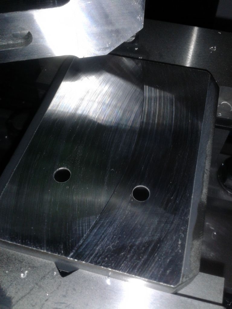
      Dished surface

      Advert
      #356720
      ChrisB
      Participant
        @chrisb35596

        Hello,

        Need some help flycutters in particular on how to make one cut an acceptable flat surface.

        I built my own cutter based on pictures I saw of a Suburban tools cutter. I had read that the mill head must be precisely adjusted to be able to get a good flat surface so I had a go at it and after what I believe was a sufficiently close adjustment of the head I proceeded with a face cut on a piece of aluminium.

        Unfortunately the result was not what I was expecting…feeding the work right to left, initially the cutter cut the workpiece with the cutter tip travelling towards me, as I continued feeding the workpiece it came to where the cutter is travelling away from me, but it did not touch the work piece.

        Then I tried feeding from left to right, the cutter travelling away from me cut the workpiece a first pass but as I continued feeding the cutter took a second cut (as it was travelling towards me) which I think was quite deep.

        Something must be wrong but I cant figure out what…the mill tilt seems to be in alignment left to right. dont know if the flycutter itself could be the cause, it's just a cutter no? there's no adjustments in it involved right?

        Not sure I'm explaining my self well as it's a bit difficult to explain myself with words – will try to post some pictures

        #356722
        Hopper
        Participant
          @hopper

          Bit of detail on how you made the flycutter, size of flycutter, and what type and size of machine you are using would help. Pics of the set up and the resulting cut surface would be invaluable as well.

          Did you "tram" the mill head using a dial indicator, to within .001"?

          Have you double checked this reading to make sure the mill head has not moved under load? Sometimes they do that if there is not a dowel pin to ensure positive location.

          Also, did you lock all slides except the one in use while making the cut? And are all gibs adjusted correctly so no excess table movement?

          Edited By Hopper on 06/06/2018 09:54:23

          #356723
          pgk pgk
          Participant
            @pgkpgk17461

            As I understand your description – Your mill head is tilted to the right or the work is canted to the left. A second pass would eliminated workpiece tilt as the cause.

            I must admit that soemtimes the visual appearnace of finish is better on my flycut pieces when mill is slightly tilted so one doesn't get the cross hatch of a level mill..particulalrly on ally and I get my best finish using a home made flycutter with a round insert on mild steel. But then there's folk here who have fly-cut a lot more stock than myself.

            pgk

            #356724
            geoff adams
            Participant
              @geoffadams14047

              Hi Chris your head is not square to the table you need to clock the head up use two paralles and a bar in the chuck as long as possible with a clock attached swing from one end of your table to the other adjust the head so the clock reads zero both ends there is videos on utube look under tramming

              Geoff

              #356727
              Neil Wyatt
              Moderator
                @neilwyatt

                Because of the large diameter of the cut, nothing is as sensitive to misalignment as flycutting.

                With a sharp tool you only need to be 0.01mm out over the diameter of the cutting circle to see a problem.

                This error would be undetectable with a normal end mill.

                Some people prefer a double cut, always cutting in the direction that gives on, saying it give the best finish.

                To be acceptable the error needs to be tiny so that the surface is still acceptably flat.

                You don't say the radius of you cutter or how far from flat the resulting surface is. I suspect that unless you used an indicator the mill may not be as well aligned as you think.

                If you don't have an indicator, you can use a shim (such as a spark plug feeler gauge – any thin metal of consistent thickness will do) between the end of the flycutter and the mill table.

                Neil

                #356730
                Mick B1
                Participant
                  @mickb1

                  The effect described means simply that the movement of the table is not truly parallel to the plane of the circle defined by the tip of the flycutter.
                  I do quite a bit of flycutting in the vertical slide on the lathe, and I just use a boring bar with a 45 deg square section toolbit ground to a vee of about 70 deg to give side and face clearances.
                  I think the problem you have relates purely to tramming of the head in the direction of feed, so that the trailing edge of the swept circle is closer to the table than the leading. Sorry if I’m stating the obvious.

                  Edited By Mick B1 on 06/06/2018 10:39:40

                  #356731
                  ChrisB
                  Participant
                    @chrisb35596

                    Yes I know, should have added more details I'm sorry.

                    So the mill is a WM18, have had it for the past year and a half, with no issues.

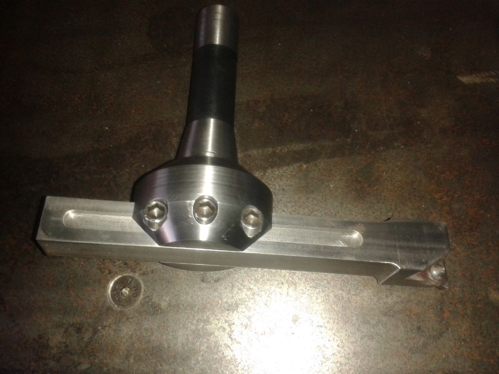
                    As for the fly cutter its this pictured below, the head mounts on to an R8 arbor – direct fit into the WM18 spindle,

                    the bar is 7inches long adjustable (I was facing at about 5" swing approx) The insert is a Seco TNMA 160408 CBM050C I want to change this to a different material, but that is what I had at the moment.

                    20180606_092138.jpg

                    The insert is angled back 7deg for clearance.

                    20180606_092153.jpg

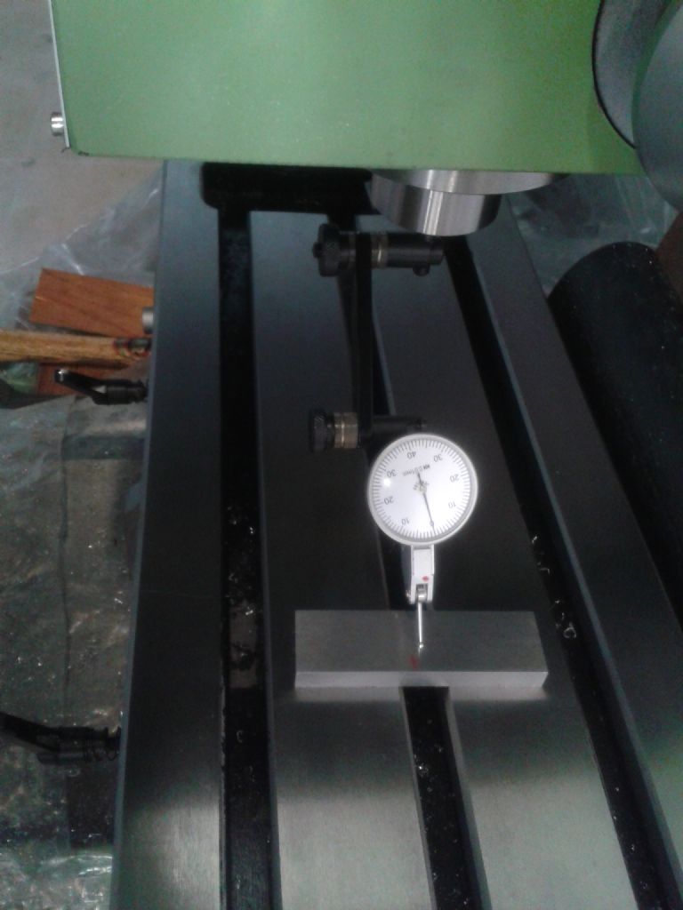
                    This is how I set up for milling, the workpiece held on parallels on a precision vice

                    20180606_082710.jpg

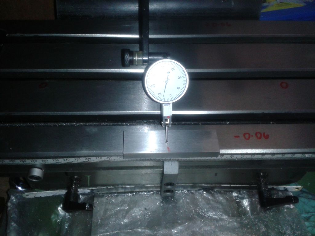
                    Checked for head tilt by means of a dti on a 6mm R8 collet directly in the spindle. Left 0mm; right 0mm; fwd -0.06mm; aft +0.06mm

                    20180606_080840.jpg

                    Cant adjust the head nod, fwd to aft but dont think it affects the surface being dished or not.

                    20180606_081436.jpg

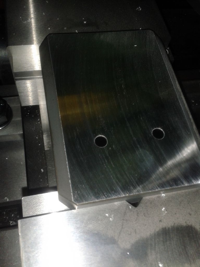
                    Surface finish, feeding right to left – initial face, and continued feeding ….

                    20180606_084504.jpg

                    ……continued feeding right to left same pass, second cut (should not have happened I think)

                    20180606_084735.jpg

                    I checked again the alignment after facing the workpiece and got exactly the same readings.

                    #356733
                    ChrisB
                    Participant
                      @chrisb35596

                      the work piece is 3" wide, I could slip a 0.06mm feeler in the middle. I set the speed at 250rpm, did not dare to go any faster because it would start vibrating above 300rpm ( It does not help to have the mill mounted on a bench on wheels – I have to sort that out)

                      Feed I cant tell, as I'm manually feeding the table but I would say I was pretty slow, maybe 1mm per 2 seconds

                      Edited By ChrisB on 06/06/2018 10:51:45

                      #356735
                      Mick Henshall
                      Participant
                        @mickhenshall99321

                        Just a thought Chris, turn the workpiece 90 degrees and shorten the overhang of the cutter

                        Mick

                        #356740
                        Vic
                        Participant
                          @vic
                          Posted by Mick Henshall on 06/06/2018 10:50:09:

                          Just a thought Chris, turn the workpiece 90 degrees and shorten the overhang of the cutter

                          Mick

                          Good idea. That’s what I would have done anyway.

                          #356741
                          Martin Kyte
                          Participant
                            @martinkyte99762

                            With a 10 inch cutting circle and the head 0.006 degrees out of perpendicular you get a 1 thou diferrence between the leading and trailing edge. With a 4 inch cutting circle the head only needs to be within 0.014 degrees for the same difference. So as Mick Henshall says reduce the swing. If the fly cutter is very out of balance that will not help either.

                            regards Martin

                            Edited By Martin Kyte on 06/06/2018 11:27:39

                            #356742
                            David Standing 1
                            Participant
                              @davidstanding1
                              Posted by ChrisB on 06/06/2018 10:45:36:

                              I set the speed at 250rpm, did not dare to go any faster because it would start vibrating above 300rpm

                              There's a clue there.

                              You don't have a fly cutter there, you have a NASA astronaut centrifuge! **LINK**

                              But seriously, I have a WM18, and it would just feel wrong to put a fly cutter with that swing on it, especially without a way of accurately counterbalancing it. That's a lot of rotational mass flying round in relation to the size of machine.

                              And to get it to cut accurately, with around a 10" swing, is a tall ask too.

                              #356743
                              Ian P
                              Participant
                                @ianp

                                I agree totally with Neil that flycutting is the highly critical indicator of tramming errors. It follows then that a flycutter is probably the best thing to use when you want to adjust the tram, however doing it really requires a very large workpiece in combination with the largest radius fly cutter.

                                If one could fasten a large sacrificial plate to the table say using countersunk fixings and then did test cuts using maximum X and Y travel then it could be trammed to near perfection. (sharp tools, spring cuts, table sag etc being taken into account). Bear in mind that even though the spindle is truly vertical, its only vertical with respect to the surface that has just been machined. That surface is the plane described by the X and Y dovetail slides, not the mill table surface which could theoretically be slightly tilted.

                                I spent quite a long time tramming my Emco mill using a micron DTI at the largest radius and the hardest part was getting a stable reading as the tip travelled over the table surface. I eventually interposed a platter out of a defunct hard disk drive as they are exceptionally flat and smooth. (BTW I'm in the group that likes to see a cross hatched pattern on the finished fly cut surface)

                                Ian P

                                #356745
                                David Standing 1
                                Participant
                                  @davidstanding1
                                  Posted by Ian P on 06/06/2018 11:51:08:

                                  (BTW I'm in the group that likes to see a cross hatched pattern on the finished fly cut surface)

                                  Ian P

                                  Me too! yes

                                  #356746
                                  ChrisB
                                  Participant
                                    @chrisb35596
                                    Posted by David Standing 1 on 06/06/2018 11:37:50

                                    You don't have a fly cutter there, you have a NASA astronaut centrifuge! **LINK**

                                    LOL! Yep, it's a bit on the larger side tbh, I sized it to be able to face over the whole width of the table if I needed…but still, I don't think you will need to spin it much faster over that swing. At 250rpm on steel the chips come out blue, so my guess is if I went any faster I'll get fireworks going. Still as mentioned, the mill bench is on wheels so I need to lift it off them to know it's real vibration speed limit.

                                    It didn't occur to me that the larger the swing the more accurate tramming needs to be, and it's not so easy to adjust, a bit fiddly…at least there is an adjuster screw on the right side of the head! While on the subject, is it possible to adjust the nod of the WM18 and is it worth doing? I counted a total of 0.12mm over the width of the table (8&quot The column has 4 allen bolts, but I cant see any discontinuity between the column and the table, seems like a solid piece.

                                    Will try as suggested, reduce the swing and rotate the work piece….will have to wait till tomorrow tho, working late shift today

                                    #356748
                                    JasonB
                                    Moderator
                                      @jasonb

                                      Stick the dti on your table and run it along in the x-x direction both without the vice on the table and also with the vice to one end as you have it in your photo.

                                      Could be table is tilting/sagging or not running parallel even though it trams 0-0 with an empty table in the central position.

                                      #356749
                                      Martin Kyte
                                      Participant
                                        @martinkyte99762

                                        Posted by ChrisB on 06/06/2018 11:58:32:

                                        , is it possible to adjust the nod of the WM18 and is it worth doing? I counted a total of 0.12mm over the width of the table (8" The column has 4 allen bolts, but I cant see any discontinuity between the column and the table, seems like a solid piece.

                                        If you can be bothered you could take the column off the base and check that there are no paint flashes or burrs fouling the mating surfaces. Don't just assume that the column is at fault though. If the column is perfect the spindle also needs to be parallel with the column. It is a hobby mill after all and with a 10 inch measuring circle you are doing a very sensitive test. Mill up and down with a 6mm slot drill and you will not even notice. Don't go chasing negligible misalignments you will drive yourself crazy.

                                        Mostly I flycut if I want a good finish rather than needing something very flat. If it has to be that flat, scrape it. Or lap it with a piece of emery on a surface plate.

                                        regards Martin

                                        #356750
                                        ChrisB
                                        Participant
                                          @chrisb35596

                                          Nah, I'm not going to take the thing apart, I'm not sending a rocket to the moon. I just want to know what's acceptable and what can be done to make it better within reason.

                                          I'll check it out Jason and report what it's like…

                                          #356751
                                          Neil Lickfold
                                          Participant
                                            @neillickfold44316

                                            Another issue is the radius of the tool is too large and requires too much tool pressure. So it flexes everything as it cuts, apart from the issue that the head/ column is not trammed to the run of the spindle. On some machines, it is not the column that needs correcting, but the work head may need shimming to get the run of the spindle true to the table. So if the head runs up and down the column, and the bottle square or you master square shows that it is within 0.02mm over 150mm or so than that is going to be OK. Then you know the error is in the assembly that is holding the spindle. It could be it needs a shim under the Pivot ring on the lower side. Looking at the numbers, it will most likely need a piece of 2 thou shim in this area for a start. It may need a 4 thou shim.

                                            Neil L

                                            #356758
                                            Muzzer
                                            Participant
                                              @muzzer

                                              The general rule of thumb with adjustable radius flycutters is surely to set the diameter of sweep so that it only just exceeds the width of the work. The various reasons for minimising the sweep are expounded above. Looking at the pics, it is clear the tool radius is set way too big.

                                              Sounds as if you got there in the end but I guess the missing part was the logic behind minimising the swing.

                                              Murray

                                              #356766
                                              Vic
                                              Participant
                                                @vic

                                                I’ve fly cut quite a few lumps of light alloy and steel and really like the finish it gives. If the head is set correctly then it will cut in both directions and give a cross hatched effect as some have said.

                                                I really dislike the look of this finish though so for small components I only traverse the cutter to the mid point so it only cuts on one stroke. This looks so much nicer but obviously only works for components that are smaller than the radius of the cutter.

                                                #356771
                                                SillyOldDuffer
                                                Moderator
                                                  @sillyoldduffer
                                                  Posted by ChrisB on 06/06/2018 10:45:36:

                                                  I set the speed at 250rpm…

                                                  Edited By ChrisB on 06/06/2018 10:51:45

                                                  I see a combination of disadvantages:

                                                  • In my world 250 rpm is 3 or 4 times too fast for fly-cutting a 5" radius.
                                                  • At large extensions that beefy tool (nice job by the way) is likely to be out of balance and the mill isn't heavy enough to fully absorb the vibration
                                                  • The mill is on wheels, which at best reduces it's ability to absorb vibration and at worse may resonate.
                                                  • A large fly radius amplifies the effect of slight tram errors and/or vibration.

                                                  Putting the mill on a solid foundation before reducing speed and cutting diameter might well make everything sweet.

                                                  Suburban's Safety Guidelines for the prototype cutter are worth a look. The wording suggests to me that Surburban expect the tool to be used on something rather heavier than a WM18. That doesn't mean it will be useless on a light hobby machine, just that you need to wind everything back a bit. The main limit looks to be the mill's ability to absorb vibration.

                                                  I have a WM18 squeezed into my garage. I think it's big. A Bridgeport is about 4 times heavier and I've seen them criticised by power users for being flimsy. I suppose it depends on what you're used to!

                                                  Dave

                                                  Edited By SillyOldDuffer on 06/06/2018 16:34:53

                                                  #356785
                                                  Martin Connelly
                                                  Participant
                                                    @martinconnelly55370

                                                    I would only set the fly cutter to be slightly wider than the work piece to keep it as stiff as possible. This also keeps the dishing due to tram errors as low as possible. It also reduces the shock when the fly cutter first contacts the work piece as it goes from cutting air to cutting metal. This will mean that the trailing stroke of the fly cutter will probably contact the workpiece. If there is a slight tram error you may find the leading stroke cuts metal and the trailing stroke polishes the surface. The effect will be different going l-r compared with r-l.

                                                    Martin C

                                                    #356795
                                                    bricky
                                                    Participant
                                                      @bricky

                                                      I used a brand new car, large brake disc to tram my mill to avoid the T slots as I rotated the quill.The brake discs are machined accuratley.

                                                      Frank

                                                    Viewing 25 posts - 1 through 25 (of 35 total)
                                                    • Please log in to reply to this topic. Registering is free and easy using the links on the menu at the top of this page.

                                                    Advert

                                                    Latest Replies

                                                    Viewing 25 topics - 1 through 25 (of 25 total)
                                                    Viewing 25 topics - 1 through 25 (of 25 total)

                                                    View full reply list.

                                                    Advert

                                                    Newsletter Sign-up