Electric Clock

Advert

Electric Clock

Home Forums Clocks and Scientific Instruments Electric Clock

Viewing 17 posts - 1 through 17 (of 17 total)
  • Author
    Posts
  • #711389
    derek hall 1
    Participant
      @derekhall1

      Hi,

      I have an Electric master clock post office type 36 that I am restoring, however the contacts that create the circuit for the impulse to the pendulum are completely destroyed.

      So my question is where can I obtain suitable replacement contacts?. I could make some but not sure of what material to use.

      I have read several articles by John Wilding and others re making electric clocks, but when it gets to the part about suitable electrical contacts and what to use, the information they give is out of date, the articles being over 30 years old now.

      Hemingway used to sell pairs of tungston contacts but don’t appear to sell  them anymore, but not sure that they would have been of use.

      Regards to all

      Derek

      Advert
      #711393
      Michael Gilligan
      Participant
        @michaelgilligan61133

        Platinum would be near-perfect [but is pricey]

        You are probably aware of this site, but I will link it for general interest:

        https://www.britishtelephones.com/clocks/clock36.htm

        and a handy diagram:

        https://www.britishtelephones.com/diagrams/gmt32d.pdf

        MichaelG.


        #711401
        peak4
        Participant
          @peak4

          I was never on maintenance, so didn’t get around to changing clock contacts; I can only presume that they have become eroded due to sparking and the lack of a spark quench circuit by a previous owner.

          If you have access to Facebook, may I suggest joining these two groups; there may well be others too
          Synchrome https://www.facebook.com/groups/405744970060647

          Telecommunications Heritage https://www.facebook.com/groups/1430472167219033

          Both are private and will need a membership request

          Next one; Are you familiar with Light Straw?
          Hard to find, but hiding on that rather clunky site is a Document List
          which contains a plethora of GPO/BT documentation, with lots about clocks, including type 36
          At first glance I couldn’t find the contact specs for that particular spring set, but a normal 3000 type would probably outlast either of us if you keep the operating current down via a slave relay before the clocks

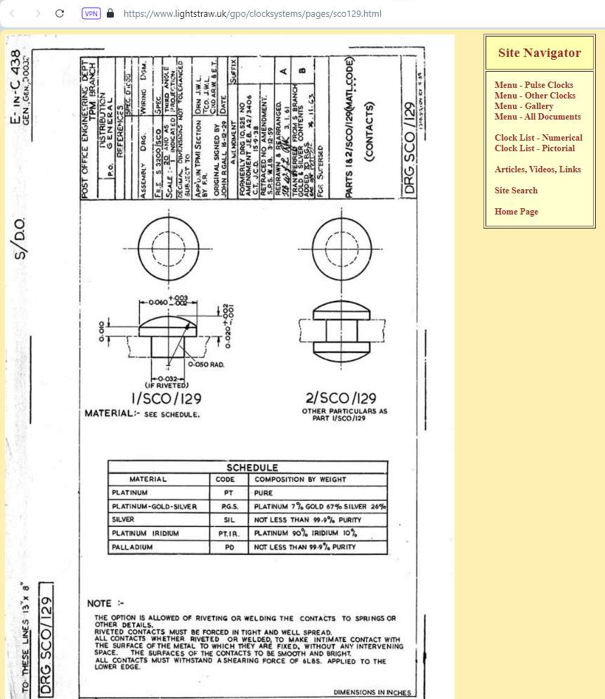
          Lurking in there, you will find This Document
          image_2024-02-02_180818909


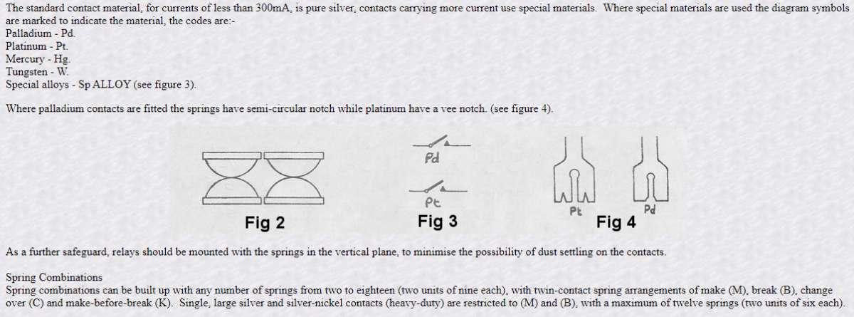
          The various contact materials are shown on the circuit diagrams and also by the shape of the ends of the springs, as per This Document from elsewhere

          image_2024-02-02_181109663

          I really need to get mine set up, but struggling for wall space and planning permission in the new house.

          Edit, I’ve just re-read your post, where you clearly said for the pendulum, not the 1/6/30 second earth contacts.
          I’ve a few spare spring sets off a ringer.
          The springs themselves will be too short, but I’m sure you could remove the contacts and rivet them into your springs

          Bill


          #711403
          John Purdy
          Participant
            @johnpurdy78347

            Derek

            Hemingway still list tungsten disks under “Engine Bay – Internal Combustion”, left hand side at the bottom under “IC Advice and Various” at the bottom of the page.

            John

            #711439
            bernard towers
            Participant
              @bernardtowers37738

              you could make your own from tig electrodes


              #711448
              duncan webster 1
              Participant
                @duncanwebster1

                Take a relay apart? The contacts are on the end of springy arms, so some creativity needed

                #711465
                John Haine
                Participant
                  @johnhaine32865

                  Similar question came up on the Synchronome group recently and someone explained how to make platinum contacts.

                  https://groups.io/g/synchronome1/topics

                  Or it may have been

                  https://groups.io/g/electric-clocks/topics

                  Both groups worth joining if you have an interest in these clocks.

                  #711478
                  SillyOldDuffer
                  Moderator
                    @sillyoldduffer

                    Somewhere lost in in my library is a book containing advice on relay contacts. From memory it’s similar to Bill’s (peak4) information above, except it goes more into the whys and wherefores.

                    Briefly, the ideal contact material is decided by how much current flows and for how long.  As an electric arc is much hotter than oxy-acetylene, up to 20,000°C, switching a heavy current requires fast acting mechanics and a contact material that can take a physical and electrical beating.  Broadly, tungsten or mercury wiped contacts for tens of amps and a noble metal like Rhodium, Palladium, or Platinum for anything smaller.  Melting points:

                    • Silver = 961°C
                    • Palladium = 1555
                    • Platinum = 1770
                    • Rhodium = 1965
                    • Tungsten = 3400

                    To keep the contacts clean, relays are designed with a wiping action that matches the contact material to the current it passes.  Although relays look simple, they’re high-tech.  When reliability matters, it’s important to choose the right type.  PO relays are optimised for 80V telephony, and the contacts burn out if overloaded, and tend to clag up so small voltages won’t switch reliably.

                    One of Bill’s documents says “The standard contact material, for currents less than 300mA, is pure silver…” That’s almost certainly what Derek’s clock needs.   Silver is high-conductivity, and – most important – Silver Oxide is conductive, so tarnished contacts will still work.   Only suitable for light duty though, because of the low melting point.   Sterling Silver is easy enough to obtain, pure if you can find it.

                    Switching an inductive load like a motor or electromagnet is likely to cause voltage spikes that maintain arcs.  Arcing causes current to flow for some time after the contacts open, which might upset set the mechanism, whilst the high temperature erodes the contact material.  The amount of metal removed by a small spark may be tiny, but it’s hot enough to evaporate Tungsten, eventually destroying the contacts.   For DC the cure is either a capacitor (about 0.1uF) across the contacts, or a diode across the coil;  AC tends to self-extinguish.

                    Rather than fix the contacts, how about cheating?  Before semi-conductors ousted them completely, PO-type relays were widely replaced by Reed Relay telephone exchanges.   Designed for small signal work, reed relays consist of a sprung contact inside a sealed tube; they’re miniature and much more reliable.  Disconnect or insulate the existing contacts, and substitute a reed-relay actuated with the existing magnet coil.


                    I’d go a step further and use a transistor!  Otherwise, as Bill & Duncan suggest, the easiest way to get good relay contacts is to scavenge them from a commercial item.

                    Most metals will work as contacts for a while, but they melt, corrode in air, and mostly have high resistivity.  For that reason TIG wire is unsuitable, as are most ordinary workshop metals.  Carbon might seem suitable because it’s used in motor brushes, but it’s too soft for relay contacts.  Copper, Brass and phosphor-bronze are OK for wiped and knife switches where positive sliding contact is guaranteed, but not for relays.What’s the difference between a Relay and a Contactor?  Not much.   Contactor is preferred by the power switching community, whilst electronics and tele-communications folk tend to talk about relays, even when their relay is switching megawatts.Dave

                    #711503
                    noel shelley
                    Participant
                      @noelshelley55608

                      Just a few thoughts ! Points as used in cars for the contact breaker, or electric fuel pump contacts SU, obviously adapted to the new purpose, pure silver ? As to sparks, think spark eroder one trick was to make a hole in a tunsten carbide cutter with a bit of copper wire ! If you just want the clock to work then go to electronic switching. Noel

                      #711506
                      peak4
                      Participant
                        @peak4

                        “For DC the cure is either a capacitor (about 0.1uF) across the contacts, or a diode across the coil;  AC tends to self-extinguish.”
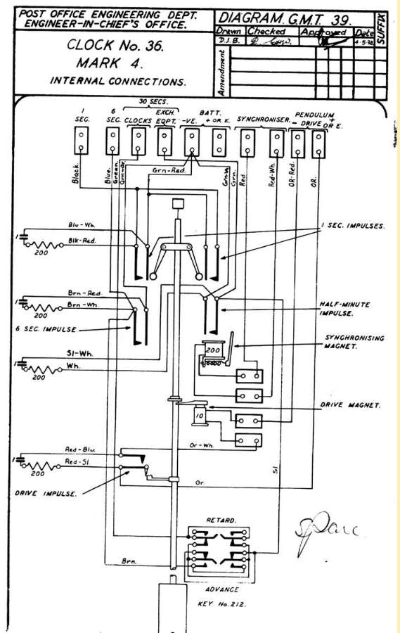
                        Almost certain that the GPO version uses a 1µF in series with a 200Ω resistor.
                        The paper capacitors were each in an oval can in a bank at the top right, with a row of wire wound resistors for the four spark quench circuits.

                        image_2024-02-03_121753927

                        Bill

                        #711529
                        derek hall 1
                        Participant
                          @derekhall1

                          Wow brilliant responses from all of you! Thanks !

                          The contacts that are damaged are part of the hipp toggle that has a 200 ohm and 1uF capacitor in the circuit as shown in Bill’s picture above. Once the circuit closes the 10 ohm coil is energised and pulls the pendulum towards it.

                          The resistor and capacitor have been tested and are ok, and the coil is the correct value.

                          Reading further it seems that a 4 v supply at around 400ma is required for the pendulum drive via the hipp Google.

                          I suspect that the previous user had too much voltage applied and fried the contacts…

                          Food for thought regarding your suggestions.

                          I would prefer to keep the originality of the clock, but I would be intrigued at using modern electronics to impulse the pendulum instead of the hipp toggle.

                          Thanks once again, and I will report back at a later date and let you know my results…

                          #711531
                          peak4
                          Participant
                            @peak4
                            On derek hall 1 Said:

                            Wow brilliant responses from all of you! Thanks !

                            The contacts that are damaged are part of the hipp toggle that has a 200 ohm and 1uF capacitor in the circuit as shown in Bill’s picture above. Once the circuit closes the 10 ohm coil is energised and pulls the pendulum towards it.

                            The resistor and capacitor have been tested and are ok, and the coil is the correct value.

                            Reading further it seems that a 4 v supply at around 400ma is required for the pendulum drive via the hipp Google.

                            I suspect that the previous user had too much voltage applied and fried the contacts…

                            Food for thought regarding your suggestions.

                            I would prefer to keep the originality of the clock, but I would be intrigued at using modern electronics to impulse the pendulum instead of the hipp toggle.

                            Thanks once again, and I will report back at a later date and let you know my results…

                            I can’t remember about the BT ones and their supply voltage, but I don’t recall any 4v supplies around.
                            I ran mine off a 12v gel battery, backed up with a trickle charger and it seemed to be OK for 20+years.
                            Clock itself ran direct from the 30 second pulse, again on 12v, but I was only running a single unit, so didn’t need any distribution relays etc.
                            I wouldn’t worry about going up on 4v as that will reduce the current to below 400mA, so shouldn’t overload the contacts. 3000 type relays would be happy with 50V anyway

                            Having looked at the impulse springset on mine, it’s only a small single contact, not twinned, and not much bigger, if any, than a single 3000 type.
                            The spare ringer springs I have use a much larger contact, so should last for ever

                            Bill

                            #711536
                            Robert Atkinson 2
                            Participant
                              @robertatkinson2

                              That triggered a memory. Many, many years ago I frequented a local scrayard the specialised in industrial material. I was a teenager and mostly looking for electronics. One day I visited and a guy was cutting the coils off hundreds of PO3000 relays (many were brand new). for the copper and throwing the rest into mixed scrap. I pointed out to the foreman that the ones with notches on the end of the contact arms (which seemed to be most of them) had Platinium contacts.
                              I never paid for any of my pickings after that 🙂 I don’t even remember how I knew about the contact identification.

                              Robert

                              #711572
                              peak4
                              Participant
                                @peak4
                                On Robert Atkinson 2 Said:

                                That triggered a memory. Many, many years ago I frequented a local scrayard the specialised in industrial material. I was a teenager and mostly looking for electronics. One day I visited and a guy was cutting the coils off hundreds of PO3000 relays (many were brand new). for the copper and throwing the rest into mixed scrap. I pointed out to the foreman that the ones with notches on the end of the contact arms (which seemed to be most of them) had Platinium contacts.
                                I never paid for any of my pickings after that 🙂 I don’t even remember how I knew about the contact identification.

                                Robert

                                When the Strowger exchanges were decommissioned around our way, the scrap contractors knew the score exactly, even down to the circuit diagram numbers of the switches & relay sets.
                                They quoted on basic numbers of unit’s, but knew which contained platinum or palladium contacts, as well as mercury wetted relays

                                Bill

                                #711641
                                Speedy Builder5
                                Participant
                                  @speedybuilder5

                                  In about 1980, we updated the company Strowger exchange for a new BT digital system. A year later, I was looking for more archive space to store customer computer printouts for the CNC machines we sold. With none available, the ‘works engineer’ said we could have the old redundant exchange room (With a smile on his face)!  I said, give me a “Scrap note’ and I would clear it out for free.

                                  So a week or so later, with a good friend of mine (Ex telecom trained) we stripped out the exchange, batteries, steel frames, bus bars and boxes and boxes of relays.

                                  I used to strip out the relay contacts and sold a jam jar full to a precious metal dealer. I still have a box of 4Ba hex headed brass screws and short 1/2” whit bolts in the stock box and some cream painted steel flats.

                                  Oh happy days!

                                  #711645
                                  John Haine
                                  Participant
                                    @johnhaine32865

                                    A good friend of mine was a manager in the London City area of BT working in Faraday House.   Walking through one of the dark recesses he came across a chap gleefully hacksawing through large bundles of laced together cc copper wires and loading the chunks into a wheelbarrow.   Graham asked him how much he was paying for the scrap.  Paying! exclaimed the guy they’re paying me to take it away!

                                    #713281
                                    derek hall 1
                                    Participant
                                      @derekhall1

                                      Update….

                                      I managed to get a relay and stripped out the contacts. I also needed to restore the hipp toggle at the same time.

                                      Following the documentation provided by “Peak4” and others I set up the buffers and springs also set the contact gap to 10 thou.

                                      I have a PSU that I set to 4v and current limit set to 500ma. The documentation suggested this is about correct.

                                      Pendulum was set swinging and the hipp toggle operates impulsing the pendulum every 30 oscillations which seems correct. No sparking at the contacts or vibration of the pendulum at impulse.

                                      I have not yet set up for the 1sec, 6sec or 30sec outputs yet though.

                                      My thoughts are to use a photocell that is triggered as the pendulum passes, the photocell signal will be used to latch a small circuit with 2 LED’s or lamps via a relay. Each LED being alternatively activated. Advantage of this is no “loading” on the pendulum and if i position the LED’s or lamps in my workshop window I can see from my kitchen window if the post office type 36 is still working !

                                      So thanks to all your suggestions and documents, as well as memories of working for the GPO.

                                      What a great forum this is!

                                      Regards to all

                                      Del

                                    Viewing 17 posts - 1 through 17 (of 17 total)
                                    • Please log in to reply to this topic. Registering is free and easy using the links on the menu at the top of this page.

                                    Advert

                                    Latest Replies

                                    Viewing 25 topics - 1 through 25 (of 25 total)
                                    Viewing 25 topics - 1 through 25 (of 25 total)

                                    View full reply list.

                                    Advert