Eccentrics

Advert

Eccentrics

Home Forums Locomotives Eccentrics

Viewing 8 posts - 1 through 8 (of 8 total)
  • Author
    Posts
  • #443197
    Paul Lousick
    Participant
      @paullousick59116

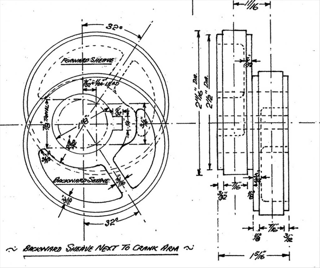
      The valve eccentrics on my Ruston Proctor SD traction engine are set at 32 degrees (as shown on the supplied drawings) and the engine is running OK but I would be interested in knowing what angle other engines are using.

      Paul

      eccentric.jpg

      Advert
      #1891
      Paul Lousick
      Participant
        @paullousick59116
        #443198
        JasonB
        Moderator
          @jasonb

          The Fowler A7 has them at 38.2deg

          #443223
          John Olsen
          Participant
            @johnolsen79199

            The ideal lead on the eccentrics will depend on the lap of the associated valve. If you are sufficiently curious, you could measure all the relevant parts and do a diagram or better yet, use the Dockstater software to see what the events are like.

            John

            #452954
            Nigel Graham 2
            Participant
              @nigelgraham2

              The angle of advance is set by the designed lead (usually a tiny bit > 0 &quot as well as lap, so varies from engine to engine, but a bit over 30º seems quite typical for Stephenson's Link-Motion, full admission port openings and fairly late full-gear cut-off.

              In fact your drawing gives what appears to be the lap (7/32 &quot and lead (that ' +1/64&#39. Which is quite possible as a traction-engine's engine itself, is designed to run fairly fast.

              If I recall aright, the angle of advance on LBSC's Maid of Kent with Ken Harris' version of its Stephenson's Gear is around 35º. A loco is designed to be driven at speed on a very early cut-off, and the effect of that link motion is to increase the lead with notching-up, especially beyond what appears typical for a traction-engine.

              The usual plots for eccentric / crank geometry are the Zeuner or the Reauleaux Diagrams, or simplified versions, both quite easy to draw. They simply relate valve-travel to crank and eccentric positions at dead-centre, but not the port openings themselves, nor the full effects of all the bits of steel in between.

              #452955
              Nigel Graham 2
              Participant
                @nigelgraham2

                Aaaarrrghh! Those blasted silly faces!

                I thought I'd given the spaces necessary to prevent them, and I cannot edit them out!

                #453022
                Nigel Bennett
                Participant
                  @nigelbennett69913
                  Posted by Nigel Graham 2 on 19/02/2020 00:36:10:

                  Aaaarrrghh! Those blasted silly faces!

                  I thought I'd given the spaces necessary to prevent them, and I cannot edit them out!

                  Perhaps you should use millimetres instead… it's the inch symbols coupled with the brackets that causes the problem! (I'll get me coat).

                  #456006
                  Nigel Graham 2
                  Participant
                    @nigelgraham2

                    Thanks Nigel!

                    Yes- I know the cause but I'd forgotten!

                    It would be beyond my computing knowledge but I do wonder if forum moderators are able to turn them off.

                    In that case too the drawing given is in inches so replying in inches was appropriate.

                  Viewing 8 posts - 1 through 8 (of 8 total)
                  • Please log in to reply to this topic. Registering is free and easy using the links on the menu at the top of this page.

                  Advert

                  Latest Replies

                  Home Forums Locomotives Topics

                  Viewing 25 topics - 1 through 25 (of 25 total)
                  Viewing 25 topics - 1 through 25 (of 25 total)

                  View full reply list.

                  Advert

                  Newsletter Sign-up