Digital caliper remote display

Advert

Digital caliper remote display

Home Forums Help and Assistance! (Offered or Wanted) Digital caliper remote display

Viewing 25 posts - 1 through 25 (of 96 total)
  • Author
    Posts
  • #309373
    Ken Weeks
    Participant
      @kenweeks58536

      I have a modified digital caliper fitted to my Myford tail stock.

      The display on the caliper is difficult to read (eyes are not what they used to be) I would like to attach a remote display nothing fancy just to display the read out figures.

      Any Ideas/suggestions?

      I have a Arceurotrade 6" Digital readout bar with remote display.

      The remote display is connected to the bar with a mini USB cable and contains two 3v battery.

      I have a cable that will fit to the caliper and I can fit a mini USB plug.

      Could this be modified for use with the display?

      Ken

      Advert
      #33041
      Ken Weeks
      Participant
        @kenweeks58536
        #309393
        Paul Lousick
        Participant
          @paullousick59116

          Hi Ken,

          Why not just replace the digital caliper on the tail stock with the 6" readout bar which already has a remote display ?

          Paul.

          #309406
          Neil Wyatt
          Moderator
            @neilwyatt

            The answer is 'probably yes' – there are a small number of different protocols, but it is likely that the readout will work with both of them.

            As long as you get the + and – on the right pins you won't cause any damage.

            Neil

            #309412
            Ketan Swali
            Participant
              @ketanswali79440

              Hi Ken,

              The answer is no, it won't work. The probability of the protocol being the same is rare. Also if you get the connections wrong, this will create further damage. Arc does not have protocol or connection information.

              Google up yurystoys and visit his site for ideas. Arc does not warrant such products for alternate connections as suggested here, so any experiments you carry out would be at your own risk.

              Ketan @ Arc.

              #309415
              mechman48
              Participant
                @mechman48
                Posted by Paul Lousick on 29/07/2017 23:31:02:

                Hi Ken,

                Why not just replace the digital caliper on the tail stock with the 6" readout bar which already has a remote display ?

                Paul.

                +1… easiest option. Another option, get a digital tyre gauge off eBay, fit a couple of neodymium magnets make up a collar to fit the tailstock barrel & you have a digital display… The tyre gauges tend to have a larger read out than calipers.

                George.

                #309432
                SillyOldDuffer
                Moderator
                  @sillyoldduffer
                  Posted by Neil Wyatt on 30/07/2017 07:52:53:

                  The answer is 'probably yes' – there are a small number of different protocols, but it is likely that the readout will work with both of them.

                  As long as you get the + and – on the right pins you won't cause any damage.

                  Neil

                  But beware that some digital calipers use a USB socket to install firmware. The socket isn't necessarily wired to match the USB standard, and the caliper itself doesn't talk USB. There are also calipers/DROs that use USB plugs and sockets to talk to a proprietary display, but aren't compatible with anything else. And then, hurrah, there are Calipers that really are USB compatible. I think you need to read the specification to find out what you've got.

                  Dave

                  #309433
                  Bob Mc
                  Participant
                    @bobmc91481

                    Hi All…

                    Ken Weeks said…

                    " I have a modified digital caliper fitted to my Myford tail stock.

                    The display on the caliper is difficult to read (eyes are not what they used to be) I would like to attach a remote display nothing fancy just to display the read out figures.

                    Any Ideas/suggestions? "

                    I made a simple DRO using an Arduino Nano and LCD display to show X&Y values from digital calipers, there is lots of information on the web available showing the Arduino programs although I couldn't find anything to show how to get 2 displays up at the same time so had to think about that one for a while….

                    Any reading can be reset to zero with the push buttons…the whole assembly is fitted in a 13Amp outlet socket and a blanking plate is used for the front panel..

                    rgds..Bob..

                    Arduino dro

                    #309639
                    Ken Weeks
                    Participant
                      @kenweeks58536

                      Thanks for all the replies.

                      Bob

                      Your reply is the sort of thing I am after but with a single axis.

                      Electronics is a bit of a closed book to me, I can assemble thing from a kit with point to point instructions but theory and programs enough said.

                      I have found a tutorial for connecting a caliper to an arduino uno but it gives the output to the USB port.

                      Any chance of more detail of you design?

                      Regards

                      Ken

                      #309643
                      Neil Wyatt
                      Moderator
                        @neilwyatt

                        Aha, fopund my pictures under Stub Mandrel:

                        Neil

                        #309646
                        Bob Mc
                        Participant
                          @bobmc91481

                          Hi Ken…

                          I don't know about the Arc digital displays but it seems as if these products are made to be hack-use unfriendly on purpose..

                          As far as using an LCD display…yes certainly… a single axis reading should be easy enough, it is fairly straightforward to connect the calipers to wiring for the Arduino although if you wanted to have a remote reset to zero then the connection is more of a problem and probably best left alone… you can reset using the calipers button.

                          The main issues with connecting up to a remote display are … setting up an LCD display…changing the voltage levels from the caliper to the Arduino…finding a program for the Arduino.. and fitting LCD and gubbins in a box, I use a 9v battery but make sure it's switched off when you finish..!

                          I will have to go and find the relevant information but will come back to you… in the meantime you will need to download the Arduino files to your pc.

                          It would help if you got a cheap Arduino Nano or any other Arduino to play about with.. these are available on ebay with the cable which connects your pc to it..

                          The voltage level changing I mentioned will require some soldering of two transistors and some resistors to a pcb… there are only 6 or so components so bear in mind that there is some hands on electronics required.

                          will be back….Bob…

                          #309727
                          Bob Mc
                          Participant
                            @bobmc91481

                            Hi Ken…

                            the diagram below shows the main items and gives an overview of how they are connected up, I used an LCD with 'Serial' connection as this is a lot easier to wire up and program … you can find them on ebay

                            One point I must address is that the dro unit gets all its instructions from the calipers and if the calipers are not adjusted within a few minutes then they switch off, consequently you can lose the position setting you had…but this is what happens normally with the calipers.

                            http://www.ebay.co.uk/itm/I2C-LCD-Display-1602-Blue-For-Arduino-Pic-Pi-/263112246526?hash=item3d42b644fe:g:cK0AAOSwvihY~Fh9

                            Will post the level shifter circuit next.

                            Overview diagram.. …

                            Arduino dro block diag.

                            #310015
                            Bob Mc
                            Participant
                              @bobmc91481

                              Due to the success of this DRO used on my lathe, I have decided to make another for the milling machine… so will chart my progress..

                              I must add that the calipers I used are the cheap ~8inch variety which seem to produce the right data format for the program I use, BUT… I can't say that the same format will be the same with any others ! … I have used the program on four sets of calipers now and they work perfectly well.

                              The Level shifter circuit as previously mentioned..below..

                              level shifter.jpg

                              In Block Diagram I showed a 'low volts psu' this can be dispensed with if the battery is kept in the calipers; In my original design I used a separate supply as per the block diagram but found that a small capacitor about 33uF was needed to cut down on noise pickup which affected the readings.

                              The Box.

                              As mentioned I used a double mains outlet socket … I found the MK modern style variety to be quite smart as it has a slight slope on the front… no I don't work for MK … the material the box is made of is some sort of plastic and mills quite easily but does produce some dust, …Wear A Mask … some of the ribs inside the blanking plate need to milled off … see pics.

                              About to be milled.

                              blanking plate before.jpg

                              After milling out.

                              blanking plate after.jpg

                              Well let me know if you want any more information.

                              rgds..Bob.

                              #310061
                              Ken Weeks
                              Participant
                                @kenweeks58536

                                Hi Bob

                                Thanks for the posts,

                                Your suggestion about searching on line produced some interesting results.

                                I have invested in a book to give me an idea what the Arduino is all about.

                                Regards

                                Ken

                                #310126
                                Bob Mc
                                Participant
                                  @bobmc91481

                                  Hi Ken..

                                  now finished front panel apart from fitting Arduino and small pcb level shifter board… as below..

                                  front panel 1.jpg

                                  lcd fitted.jpg

                                  Above ^ the blue square is the lcd brightness control.

                                  front panel 2.jpg

                                  #310364
                                  Bob Mc
                                  Participant
                                    @bobmc91481

                                    Have been doing some more work soldering the Arduino Nano and level shifting components on the pcb, this is done prior to fitting the pcb in the box, I am 'hot glueing' the LCD and veroboard pcb in place, it can be removed if necessary with a bit of heat .

                                    I will be trying this set up using a caliper for the 'y' axis only … I intend to use a rotary encoder for the 'x' axis, and as you are only interested in one axis display I won't be showing any of the rotary encoder workings.

                                    pic below…. the pcb component side .. minus transistors…you may note I have two sets of components either side of the Arduino, this is initially for the two sets of level shifters ie, one for 'x' axis calipers and one for 'y' axis caliper.. for a single axis you obviously only need to have one set of these.

                                    dro pcb1.jpg

                                    Below … the other side but not yet cut the tracks .

                                    dro pcb2.jpg

                                    Below…I cut out a slot to take the Arduino mini usb port and trial fitted the board.

                                    pcb trial fit in box.jpg

                                    So… its coming on… hope to have it up and running in a day or two…and let you see the program … just hope all Arduino experts are not looking… but hey who cares ! … so long as it does what it is supposed to do.

                                    ..Bob…

                                    #310371
                                    SillyOldDuffer
                                    Moderator
                                      @sillyoldduffer

                                      Like it Bob! Never thought of using a socket box to make a portable enclosure; that's a really good idea.

                                      I've been inspired to stick an oscilloscope on my various digital calipers to see which, if any, are sending data. I can think of a few examples where having an external display on a caliper would be useful.

                                      Dave

                                      Edited By SillyOldDuffer on 04/08/2017 17:19:12

                                      #310383
                                      Ken Weeks
                                      Participant
                                        @kenweeks58536

                                        Hi Bob

                                        Thanks for the posts.

                                        As you suggested I have been doing more research on the W,W,W, and came across this site

                                        DRO with Arduino and digital calipers by Scrachi – Thingiverse

                                        He gives an concise explanation for making a 3 axis display c/w code using a Arduino Uno,

                                        Another one I have found suggest using a Logic Level Shifter, 4-Channel, Bidirectional between the caliper and the Arduino Uno.,

                                        With a bit of thought they could be combined to make a single axis read out and the code could be amended to suit

                                        Regards

                                        Ken

                                        #310409
                                        IanT
                                        Participant
                                          @iant

                                          I see Chronos now sell a caliper with a Bluetooth connection built in – and wondered if this was a simpler way to do this kind of thing (straight to a phone app) ??

                                          Regards,

                                          IanT

                                          #310412
                                          Bob Mc
                                          Participant
                                            @bobmc91481

                                            Thanks Ken, Dave, Ian..

                                            Yes Ian… I got an email advert this morning about the bluetooth connection app for a digital caliper… but could the idea be used in a 2 or 3 axis requirement..? .

                                            The other thing is that I am actually only going to use one caliper on the Y axis on my milling machine as there is not much travel, however the X axis is quite long and I intend to use a rotary encoder which I purchased some time ago and am determined I am going to use it on something!

                                            Anyway… the real reason is that I get such a feeling of satisfaction from doing things my own way and when it works and looks the part I am on cloud 9…!

                                            Thanks for all your posts … it is a real buzz to get appreciation.

                                            Bob..

                                            #310431
                                            Enough!
                                            Participant
                                              @enough

                                              Posted by Bob Mc on 04/08/2017 20:45:08:

                                              I intend to use a rotary encoder which I purchased some time ago and am determined I am going to use it on something!

                                              Might be the same one I bought that's sitting in a dollar-store box on a high shelf labelled "rotary encoder – don't throw out". I should really go back to that.

                                              #310568
                                              Bob Mc
                                              Participant
                                                @bobmc91481

                                                So… I finally finished it…

                                                (I can't post all of this in one go on the forum) this is Part 1. Program is Part 2.

                                                Ken did mention an IC level shifter which is a better idea, but I had a load of small signal transistors in me junk box and I was getting impatient… so just cobbled it together.

                                                The 1.5v supplies for the calipers were simply taken from a potential divider which has a 6k2 connected to the 3v3 output of the Arduino and a 4k7 down to ground 0v … gives about 1.4v at the mid point.

                                                The wiring to the Arduino is best followed using the program inputs .. you will see clockpinx and datapinx and clockpiny and datapiny defined.

                                                I used a D type connector for the two calipers.. there is not much wiring to do, I did however wire reset to zero switches in the box which just ground the reset buttons in the calipers, you would have to take the calipers apart to fit wiring and I must say it is a bit fiddly, there is not much room for manouver… or is is manouvre sorry can't spell.

                                                One thing which was different with the Lcd I purchased was that the I2C address was slightly different but there seem to be only two addresses used…. either 0x3F of 0x27.

                                                The program below is for use with two calipers which I just put together with a minimal knowledge of programming and copying what was on the www.

                                                Hope you might find some of the build info useful.. if you have any questions let me know … just don't ask me difficult questions about programming..!!

                                                #310569
                                                Bob Mc
                                                Participant
                                                  @bobmc91481

                                                  Part 2.

                                                  int i;
                                                  int sign;
                                                  long value;
                                                  float resultx;
                                                  float resulty;
                                                  int clockpinx = A2;
                                                  int datapinx = A0;
                                                  int clockpiny = 7;
                                                  int datapiny = 9;
                                                  unsigned long tempmicrosx;
                                                  unsigned long tempmicrosy;

                                                  #include <Wire.h>

                                                  #include <LiquidCrystal_I2C.h>

                                                  LiquidCrystal_I2C lcd(0x27, 2, 1, 0, 4, 5, 6, 7, 3, POSITIVE);

                                                  void setup()
                                                  {
                                                  {pinMode(clockpinx, INPUT);
                                                  pinMode(datapinx, INPUT);
                                                  }
                                                  {
                                                  pinMode(clockpiny, INPUT);
                                                  pinMode(datapiny, INPUT);
                                                  }

                                                  Serial.begin(9600);

                                                  lcd.begin(16,2);
                                                  lcd.backlight();

                                                  { lcd.setCursor(0,0);
                                                  lcd.print("X val mm&quot;

                                                  lcd.setCursor(0,1);
                                                  lcd.print("Y val mm&quot;
                                                  }

                                                  }

                                                  void loop() {
                                                  ReadX();

                                                  }

                                                  void ReadX(){

                                                  //This is for reading the caliper x data.

                                                  while (digitalRead(clockpinx)==HIGH) {} //if clock is LOW wait until it turns to HIGH
                                                  tempmicrosx=micros();

                                                  while (digitalRead(clockpinx)==LOW) {} //wait for the end of the HIGH pulse

                                                  if ((micros()-tempmicrosx)>1000) { //if the HIGH pulse was longer than 1000 micros we are at the start of a new bit sequence
                                                  decodex(); //decode the bit sequence

                                                  }
                                                  }

                                                  void decodex()
                                                  {
                                                  //this turns the binary code of x data into a decimal value.
                                                  sign=1;
                                                  value=0;
                                                  for (i=0;i<23;i++) {

                                                  while (digitalRead(clockpinx)==HIGH) { } //wait until clock returns to HIGH- the first bit is not needed
                                                  while (digitalRead(clockpinx)==LOW) {} //wait until clock returns to LOW
                                                  if (digitalRead(datapinx)==LOW)

                                                  {
                                                  if (i<20)

                                                  {
                                                  value|= 1<<i;
                                                  }
                                                  if (i==20)

                                                  {
                                                  sign=-1;
                                                  }
                                                  }
                                                  }
                                                  resultx = ((value*sign)/100.0);
                                                  lcd. setCursor(10,0);

                                                  lcd.print(resultx,4);

                                                  ReadY();
                                                  } ///END

                                                  void ReadY(){

                                                  //This is for reading the caliper Y data.

                                                  while (digitalRead(clockpiny)==HIGH) {} //if clock is LOW wait until it turns to HIGH
                                                  tempmicrosy=micros();

                                                  while (digitalRead(clockpiny)==LOW) {} //wait for the end of the HIGH pulse

                                                  if ((micros()-tempmicrosy)>1000) { //if the HIGH pulse was longer than 1000 micros we are at the start of a new bit sequence
                                                  decodey(); //decode the bit sequence

                                                  }
                                                  }

                                                  void decodey()
                                                  {

                                                  sign=1;
                                                  value=0;
                                                  for (i=0;i<23;i++) {

                                                  while (digitalRead(clockpiny)==HIGH) { } //wait until clock returns to HIGH- the first bit is not needed
                                                  while (digitalRead(clockpiny)==LOW) {} //wait until clock returns to LOW
                                                  if (digitalRead(datapiny)==LOW)

                                                  {
                                                  if (i<20)

                                                  {
                                                  value|= 1<<i;
                                                  }
                                                  if (i==20)

                                                  {
                                                  sign=-1;
                                                  }
                                                  }
                                                  }
                                                  resulty = ((value*sign)/100.0);

                                                  lcd. setCursor(10,1);
                                                  lcd.print(resulty,4);

                                                  ReadX();
                                                  }

                                                  #310666
                                                  SillyOldDuffer
                                                  Moderator
                                                    @sillyoldduffer

                                                    Thanks for publishing the program Bob.

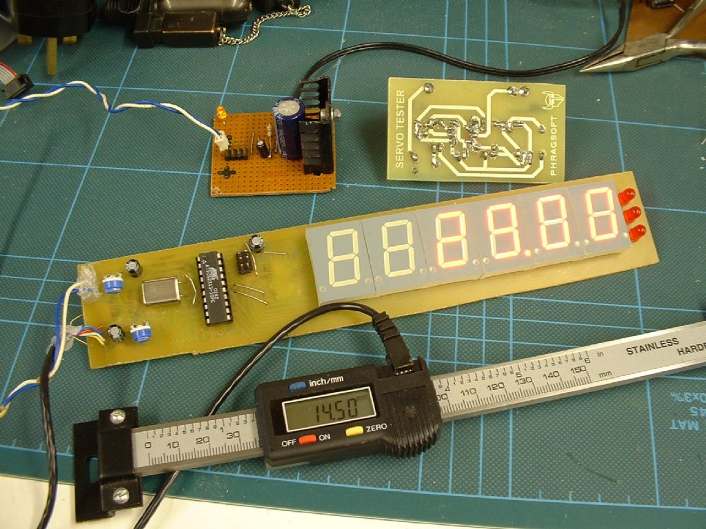
                                                    Poking my calipers with an oscilloscope revealed this:

                                                    caliper.jpg

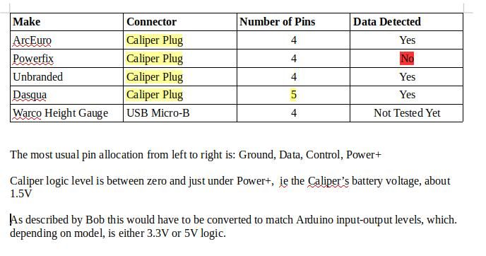
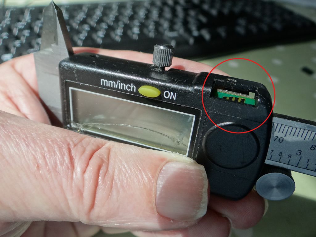
                                                    The first problem to overcome is the connector, which I've described as a 'Caliper Plug'. I don't think it's a standard fitting so my first problem will be to make one! It has to fit into the rectangular hole ringed red in the photo, which is normally hidden under a cover.

                                                    dsc04509.jpg

                                                    Anyway, the table shows that one of my calipers won't play, but the other three probably will. The Dasqua has a 5 pin socket (ground on the left) and will need a different plug. Although the height gauge has a real USB socket, it's not computer compatible USB. I expect to find when I've had time to break out the USB connector that the signalling is the same as the other calipers. If so, then not a good idea to plug the height gauge into a computer because the higher voltage computer could damage the caliper and perhaps itself in the process.

                                                    Dave

                                                    #310669
                                                    SillyOldDuffer
                                                    Moderator
                                                      @sillyoldduffer

                                                      Posted by Bob Mc on 05/08/2017 19:22:53:

                                                      One thing which was different with the Lcd I purchased was that the I2C address was slightly different but there seem to be only two addresses used…. either 0x3F of 0x27.


                                                      0x27 and 0x3F seem to be the most common but others are used. If anyone gets stuck with an IC2 display that won't work with one of Bob's values, I found this sketch on the web. It scans the LCD for a valid IC2 address and tells you what it is.

                                                      Apologies for the indentation; the forum software removes it!

                                                      #include
                                                      #include LiquidCrystal_I2C* lcd;

                                                      // UNO : SDA=A4 SCL=A5
                                                      // I2C Scanner
                                                      // Written by Nick Gammon
                                                      // Date: 20th April 2011

                                                      #include

                                                      void setup() {
                                                      Serial.begin (115200);

                                                      // Leonardo: wait for serial port to connect
                                                      while (!Serial)
                                                      {
                                                      }

                                                      Serial.println ();
                                                      Serial.println ("I2C scanner. Scanning …" )   ;
                                                      byte count = 0;

                                                      Wire.begin();
                                                      for (byte i = 8; i < 120; i++)
                                                      {
                                                      Wire.beginTransmission (i);
                                                      if (Wire.endTransmission () == 0)
                                                      {
                                                      Serial.print ("Found address: " )  ;
                                                      Serial.print (i, DEC);
                                                      Serial.print (" (0x" )  ;
                                                      Serial.print (i, HEX);
                                                      Serial.println (" "  )   ;
                                                      count++;
                                                      delay (1); // maybe unneeded?
                                                      } // end of good response
                                                      } // end of for loop
                                                      Serial.println ("Done." )   ;
                                                      Serial.print ("Found " )  ;
                                                      Serial.print (count, DEC);
                                                      Serial.println (" device(s)." ) ;
                                                      lcd = new LiquidCrystal_I2C( 0x3f, 16, 2 );
                                                      setup1();
                                                      } // end of setup

                                                      void setup1()
                                                      {
                                                      lcd->init(); // initialize the lcd
                                                      // Print a message to the LCD.
                                                      lcd->backlight();
                                                      lcd->print("Hello, worldy!" ) ;
                                                      }
                                                      void loop()
                                                      {
                                                      }

                                                      Lots of edits to remove poxy automatic smileys

                                                      Edited By SillyOldDuffer on 06/08/2017 13:11:05

                                                      Edited By SillyOldDuffer on 06/08/2017 13:14:21

                                                      Edited By SillyOldDuffer on 06/08/2017 13:15:28

                                                      Edited By SillyOldDuffer on 06/08/2017 13:16:40

                                                    Viewing 25 posts - 1 through 25 (of 96 total)
                                                    • Please log in to reply to this topic. Registering is free and easy using the links on the menu at the top of this page.

                                                    Advert

                                                    Latest Replies

                                                    Viewing 25 topics - 1 through 25 (of 25 total)
                                                    Viewing 25 topics - 1 through 25 (of 25 total)

                                                    View full reply list.

                                                    Advert

                                                    Newsletter Sign-up