DC motor Operation – Q&A

Advert

DC motor Operation – Q&A

Home Forums General Questions DC motor Operation – Q&A

Viewing 25 posts - 1 through 25 (of 32 total)
  • Author
    Posts
  • #129537
    Anonymous

      I thought I'd start this thread rather than continue to hijack a previous thread while trying to improve my understanding of DC motors.

      I think we've already covered permanent magnet, and shunt wound DC motors. Essentially the speed is directly proportional to applied voltage, and torque is directly proportion to armature current.

      Now to tackle series wound motors. It made my head hurt thinking about these. In a series wound motor the field coils and armature are in series, so the the same current flows through both. As before let's start with a 'perfect' motor, ie, no mechanical or electrical losses. If we apply a voltage across the terminals a current flows in both the field winding and armature. The interaction between magnetic field generated by the field coils and that generated by the armature causes the motor to start turning. As before, when the armature turns it also generates a back emf which reduces armature current. But this same current flows through the field windings, so the strength of the magnetic field from the field windings decreases. This is where my head starts hurting. In order to maintain the same back emf the armature has to turn faster because the field strength has decreased. But as the motor turns faster the current decreases still further and so on ad inifinitum, until the armature goes bang!

      In practise mechanical and electrical losses will limit the speed to a finite number, but not necessarily low enough to prevent damage to the motor.

      Does this argument seem reasonable?

      Regards,

      Andrew

      Advert
      #22826
      Anonymous
        #129538
        Les Jones 1
        Participant
          @lesjones1

          Hi Andrew,
          That is the same as my understanding of series motors. One thing I did consider was using a series motor from a washing machine as a shunt motor. (For better speed regulation.) I found that the resistance ov the field winding was very low. It would have required a very low voltage powering the field. (Less than 5 volts if I remember correctly – I did not keep any notes about the experiment.)

          Les.

          #129539
          jason udall
          Participant
            @jasonudall57142

            Am I missing something.
            More rpm.》.more back emf 》less current》 less torque》 less rpm less back emf 》more current 》more torque more rpm……ie will tend to regulate …

            #129540
            jason udall
            Participant
              @jasonudall57142

              I believe its called negative feedback

              #129541
              Michael Gilligan
              Participant
                @michaelgilligan61133

                This seems to be a reasonable introductory text.

                MichaelG.

                #129543
                Les Jones 1
                Participant
                  @lesjones1

                  Hi Jason,
                  I think it could be considered negative feedback in terms of torque. The torque will be proportional to the square of the current. In terms of speed I think it is more like positive feedback.

                  Les.

                  #129545
                  john fletcher 1
                  Participant
                    @johnfletcher1

                    Regarding running an ex washing machine seies wound motor as a shunt wound motor Jim ???? who other name I can't remember wrote a small book published by model engineering and he gave details of what he found when doing just that. As you say the field resistance is low, I ran a modified one as a seperately excited shunt wound generator several years ago, I think I energised the field from a 12 volt battery. I was just sort of playing around and didn't keep details, but it did work OK. The motors are well made, have very good balance, but rely on speed to obtain the power, they have a nice pair of bearings, very useful for other for other projects. I modified a Hoover pcb to give speed control, just got it working then some did an article in MEW on the very same thing. Motors on the latest machines with digital control are much the same, they are also fitted with a tacho for feed back.If you are interested in power electronic,there some very good components on early type printed circuit boards ready for removal,not so on the digital ones,shame. Ted

                    #129546
                    jason udall
                    Participant
                      @jasonudall57142

                      Les please explain..it would suggest “possitve feeback” implies more rpm 》more rpm…ie runnaway..but where would the energy come from..

                      #129547
                      Les Jones 1
                      Participant
                        @lesjones1

                        Hi Ted (john fletcher 1),
                        I have not seen the book you mention, All of the speed control boards I have seen contained an IC on which I could find no data. All the motors I have removed had tacho feedback which was just a magnet and a coil generating an output frequency proportional to speed. I think they all used an analog control loop. I have read somewhere that some modern machines use brushless DC motors. I would be interested in playing with one of these if I ever come accross a scrap one.

                        Les.

                        #129548
                        John Stevenson 1
                        Participant
                          @johnstevenson1

                          Andrew forgive me for the hijack but it's just a heads up for the future.


                          Fork trucks run on DC motors [ the electric ones that is smiley ] the motor is the most expensive part on the truck and the most unreliable, some of these can cost 4K each. Because they also run at usually 48 volts normally the control gear has to be big and heavy to handle the current so not cheap.


                          Modern trend is to now run them on 440 v 3 phase motors, so cheap and the control gear is far lighter to supply these.


                          The magic bit is a 48 v DC inverter that takes it up to 440v 3 phase and given moder electronics they seem very reliable.


                          So a few years into the future as these get scrapped out could be a nice source of genuine clean 3 phase power at 440 volts.


                          John S.

                          Edited By John Stevenson on 13/09/2013 18:43:40

                          #129549
                          MICHAEL WILLIAMS
                          Participant
                            @michaelwilliams41215

                            ” In order to maintain the same back emf the armature has to turn faster because the field strength has decreased. But as the motor turns faster the current decreases still further and so on ad inifinitum, until the armature goes bang! “

                            That is basically what happens .

                            Running speed is determined mainly by the mechanical load .

                            Top end speed is limited only by :

                            windings resistance ,
                            rise time of current in the armature coils and by magnetic saturation .

                            Series wound motors can and do run away to destruction when for instance a heavy load is suddenly removed .

                            The very bad speed regulation and the general tendency to run-away are the reasons that series wound motors are so unsuitable for things like tool grinders .

                            The situation can be improved considerably using a bit of feed back and simple electronics .

                            Final note : Most books giving simple DC motor theory assume an ‘ideal’ power source which maintains applied voltage regardless of current . In practice the internal resitance of the power source and the dropping terminal voltage under load can have significant effect on the motor characteristic and particularly the top end speed .

                            MikeW

                            #129550
                            Michael Gilligan
                            Participant
                              @michaelgilligan61133
                              Posted by john fletcher 1 on 13/09/2013 18:08:04:

                              Regarding running an ex washing machine seies wound motor as a shunt wound motor Jim ???? who other name I can't remember wrote a small book published by model engineering and he gave details of what he found when doing just that.

                              <etc.>

                              Ted

                              .

                              That would be Jim Cox … Workshop Practice No. 16.

                              MichaelG.

                              #129551
                              Les Jones 1
                              Participant
                                @lesjones1

                                Hi Jason,
                                As Andrew describes with a theoretically ideal series motor on no load runaway will occur. As the speed goes up the back emf increases. The difference between the supply voltage and the back emf will be less. This difference is the voltage across the field coils so the field current is reduced which means the motor must go faster to produce the same back emf. As the motor is producing no external torque there is no energy output. all the energy that has been supplied to the motor will be stored as kinetic energy in the rotating mass of the motor.

                                Les.

                                #129552
                                Ian P
                                Participant
                                  @ianp
                                  Posted by John Stevenson on 13/09/2013 18:42:06:

                                  Modern trend is to now run them on 440 v 3 phase motors, so cheap and the control gear is far lighter to supply these.

                                  The magic bit is a 48 v DC inverter that takes it up to 440v 3 phase and given moder electronics they seem very reliable.

                                  So a few years into the future as these get scrapped out could be a nice source of genuine clean 3 phase power at 440 volts.

                                  John S.

                                  John

                                  Well you could be right but to generate enough amps at 48V to drive the inverter will require a substantial power supply (or batteries and a charger) if the 440Voutput from the inverter is going to do any useful work.

                                  I don't see why the 'genuine clean' 440V will be any cleaner then the three phase synthesised in the common VFD. It only has to clean enough for the job, not clean enough for an operating theatre

                                  May as well convert the 240V mains to 440V with a simple autotransformer (with a VFD) its greener too.

                                  Ian P

                                  #129554
                                  jason udall
                                  Participant
                                    @jasonudall57142

                                    Les..”stored as kinetic energy in the rotating mass” …which is increasing in rpm
                                    ….I think from memory proportional to the square of theta or rpm”

                                    #129557
                                    Russell Eberhardt
                                    Participant
                                      @russelleberhardt48058

                                      Your argument is quite correct Andrew. A series would motor with no load will run away. The load will control the speed but the regulation (speed vs torque) is very poor.

                                      So why are they used? They have very high starting torque ( and current of course ) so can be used for example for car starter motors and for traction motors for everything from milk floats to railways.

                                      Russell.

                                      #129568
                                      Anonymous

                                        Thanks all for the comments, and for confirming that I have the basic idea correct. It was the ever increasing speed that made my head hurt! But, as Les says, I eventually realised that in the 'ideal' motor there is no energy loss, and ultimately no torque, so the speed can be whatever it likes.

                                        I don't know what the output waveforms of the inverters described by JohnS look like, but I can assure you that the output of VFD doesn't look anything like a 3-phase sinusoid. It is essentially three PWM waveforms, so constant amplitude, but varying duty cycle. There is no equivalent of the 'neutral' line so if you look at the output of a VFD you are effectively looking phase to phase. If you use an oscilloscope to look at the outputs it would be advisable to use a high voltage differential probe to avoid nasty surprises.

                                        Regards,

                                        Andrew

                                        #129579
                                        Muzzer
                                        Participant
                                          @muzzer

                                          Take a look at Curtis Instruments for typical inverters that are used in materials handling, utility and leisure vehicles (link below). They do controllers for brushed (series) DC motors as well as asynchronous (induction) and synchronous (permanent magnet). However, they don't boost the voltage up to mains levels. Instead they design the motors for the battery voltage in the first place.

                                          For higher power applications, the battery voltage will tend to be higher to avoid silly currents and resulting lower efficiency. However, as you can see, they do 24V induction motor drives.

                                          As Andrew says, the voltage is a PWM waveform but of course the current is smoothed by the inductance of the motor and is controlled to be a very smooth and accurate sinusoid. Most industrial motors nowadays are designed to tolerate the different voltage waveform which puts higher voltages stresses on the insulation but I've never had a problem with "old" motors when driven by a modern VFD.

                                          **LINK**

                                          Muzzer

                                          #129594
                                          MICHAEL WILLIAMS
                                          Participant
                                            @michaelwilliams41215

                                            When it comes to large power DC motors electrical engineers soon realised that neither simple design series or shunt wound motors were ideal for general purposes so various methods were soon developed to get more suitable running characteristics and make motors easier to control .

                                            Many and varied were the methods used – just a few examples :

                                            Making compound wound motors with both series and shunt field windings to get a more useful compromise characteristic .

                                            Having input tappings on field windings of series motors so that while the same current still went through armature and field coils the number of ampere turns in the field coils could be changed to get strong/weak field .

                                            Using mechanical governing of series wound motors :

                                            Just to trip an on/off switch and/or apply an emergency brake .

                                            To work a resistive or tap changing controller .

                                            Most of the problems of designing and controlling large motors had been solved long before the electronic age .

                                            Early power electrical systems are a fascinating subject to study .

                                            MikeW

                                            #129595
                                            Sub Mandrel
                                            Participant
                                              @submandrel

                                              As you say, they will just go faster and faster until mechanical losses limit the speed, which for a well made motor might be 'quite fast'.

                                              'Duplex' wrote a a small grinder for ME that was based on a simple 'universal (i.e. series wound) motor.

                                              It had a typically neatly made, but crude in action, adjustable brake to limit the off-load speed.

                                              Personally I woudl think this was a very silly way to make a grinding machine…

                                              Neil

                                              #129600
                                              MICHAEL WILLIAMS
                                              Participant
                                                @michaelwilliams41215

                                                Just one more mention –

                                                In pre electronic days large motors were often ‘ driven ‘ by a human operator who had to work the resistive and tap changing starting and running controls directly .

                                                This was skilled work and perhaps incredibly motors were still being manually controlled this way up until very recent times in coal mines and rolling mills .

                                                A similar system was also used on some of the early electric railway engines and lived on in simplified form on some of the Underground trains until just a few years ago .

                                                MikeW

                                                Edited By MICHAEL WILLIAMS on 14/09/2013 09:51:04

                                                #129610
                                                Russell Eberhardt
                                                Participant
                                                  @russelleberhardt48058
                                                  Posted by MICHAEL WILLIAMS on 14/09/2013 09:24:10:

                                                  Early power electrical systems are a fascinating subject to study .

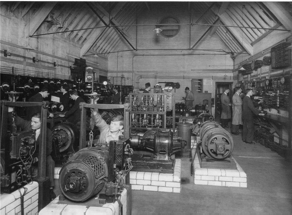
                                                  You mean like this?

                                                  battersea_machines_lab.jpg

                                                  That's where I did my study of electrical machines. The only "electronics" was the mercury arc rectifier and inverter. There was three phase ac on open brass terminals at that bench on the right. The HSE would have a field day there now!

                                                  Russell.

                                                  #129618
                                                  Anonymous

                                                    When I was deciding which university to attend I saw an electrical machines lab like that during one visit. And the guide was very proud that some of the machines were made in the 1890s. Put me right off, at the time. It didn't help that it poured down all day and on the bus ride from the railway station to the campus all I could see were damp, drab concrete buildings.

                                                    Regards,

                                                    Andrew

                                                    PS: Note the bus journey; none of the modern trend where the university tours are as much for the parents as the prospective students. I think the most my parents did was give me a lift to the railway station in my home town. wink

                                                    Edited By Andrew Johnston on 14/09/2013 10:55:31

                                                    #129630
                                                    Howard Lewis
                                                    Participant
                                                      @howardlewis46836

                                                      The risk is that a Series Wound Motor, off load will run faster and faster until it self destructs, as postulated in the original post.

                                                      Usually, what prevents this are the friction in the bearings and the windage on the rotor, which provide sufficient load to keep the speed below that where the centirfugal forces cause rotor windings to fly off.

                                                      Having said that, better not to find out the hard way that your motor is low friction and/or internall very aerodynamic!

                                                      Howard

                                                    Viewing 25 posts - 1 through 25 (of 32 total)
                                                    • Please log in to reply to this topic. Registering is free and easy using the links on the menu at the top of this page.

                                                    Advert

                                                    Latest Replies

                                                    Home Forums General Questions Topics

                                                    Viewing 25 topics - 1 through 25 (of 25 total)
                                                    Viewing 25 topics - 1 through 25 (of 25 total)

                                                    View full reply list.

                                                    Advert

                                                    Newsletter Sign-up