DC-DC converter

Advert

DC-DC converter

Home Forums Electronics in the Workshop DC-DC converter

Viewing 25 posts - 26 through 50 (of 73 total)
  • Author
    Posts
  • #460970
    Michael Gilligan
    Participant
      @michaelgilligan61133
      Posted by duncan webster on 30/03/2020 11:24:57:

      According to the interweb typical AAA battery is 1000 mAh at 1.5 V, SR44 is 200 mAh at 1.55 V. Apart from being a bit numb to handle I would not expect any issues with fastening a AAA battery holder to the back of your caliper.

      AAA are a lot cheaper and will last longer. If you're a real cheapskate you could fit a switch. Rechargeable are 1.2V might work? Neil's 1.22V did

      .

      Yes, Duncan … that’s why I emphasised the word may

      MichaelG.

      Advert
      #460972
      not done it yet
      Participant
        @notdoneityet
        Posted by Michael Gilligan on 30/03/2020 11:05:15:

        Posted by not done it yet on 30/03/2020 08:05:13:

        In addition to the KISS principle (use a 1.5V rechargeable cell), why would anyone even consider using goodness how many times the electrical power, for no good reason, a sensible option

        A rechargeable AAA cell should last several(?) weeks […]

        ?

        That may be a little too stupidly simple

        The SR44 is specified for many digital calipers

        Probably wise to compare voltages, before assuming that a rechargeable AAA cell will suffice.

        MichaelG.

        Perhaps you have not (properly) read the first post in this thread (or maybe you are getting a little forgetful?)

        Here it is to help you remember? :

        I am using a Buck converter to step down 12v DC to 1.5 volts to drive some digital callipers (Modified for the Z axis of the mill). My bolding and underlined value.

        My post was specifically related to the thread. Maybe you could do likewise?

        #460974
        Michael Gilligan
        Participant
          @michaelgilligan61133

          Posted by Andrew Johnston on 30/03/2020 11:31:50:

          […]

          I've had another read of the LM2596 datasheet. Not a great fan of TI datasheets (the old Nat Semi ones were better), but buried in the applications section is a note saying the IC is perfectly happy running in discontinuous mode, even if designed to run in continuous mode. It's been a long time since I used any of the Simple Switcher IC family, but I don't recall any particular instability problems at low currents. They should operate at tens or hundreds of milliamps without stability problems. Although of course there will be greater output voltage ripple and the unit will be noiser due to ringing on the switching edges.

          .

          Thanks, Andrew yes

          MichaelG.

          #460976
          Michael Gilligan
          Participant
            @michaelgilligan61133
            Posted by not done it yet on 30/03/2020 12:32:03:

            Posted by Michael Gilligan on 30/03/2020 11:05:15:

            Posted by not done it yet on 30/03/2020 08:05:13:

            In addition to the KISS principle (use a 1.5V rechargeable cell), why would anyone even consider using goodness how many times the electrical power, for no good reason, a sensible option

            A rechargeable AAA cell should last several(?) weeks […]

            ?

            That may be a little too stupidly simple

            The SR44 is specified for many digital calipers

            Probably wise to compare voltages, before assuming that a rechargeable AAA cell will suffice.

            MichaelG.


            Perhaps you have not (properly) read the first post in this thread (or maybe you are getting a little forgetful?)

            Here it is to help you remember? :

            I am using a Buck converter to step down 12v DC to 1.5 volts to drive some digital callipers (Modified for the Z axis of the mill). My bolding and underlined value.

            My post was specifically related to the thread. Maybe you could do likewise?

            .

            Oh please !

            Do tell me where you can find 1.5 volt rechargeable AAA cells.

            MichaelG.

            .

            Edit: Here is a datasheet for an Energizer 357 [SR44]

            https://data.energizer.com/pdfs/357-303z.pdf

            Edited By Michael Gilligan on 30/03/2020 12:56:11

            #460988
            Martin Kyte
            Participant
              @martinkyte99762

              You are perfectly correct Andrew, being a more expirienced switcher designer than me. My usage of switchers is limited to high current LED drivers for biogenetics usually at fixed current with low frequency PWM for dimming where neccesary.

              I should have said near to saturation with as I understand it the max ON phase current bringing the inductor to the point of saturation just before it switches off. This being the flattest part of the BH curve. If I'm wrong I would be delighted to be enlightened. Any increase in understanding is always welcome. My thrust was it's the wrong module for the job. Yes it will work happily in discontinuous mode but the combination of regulate then 'freefall' doesnt suit the appliction as you say due to the high ripple.

              regards Martin

              #460996
              not done it yet
              Participant
                @notdoneityet

                Oh please !

                Do tell me where you can find 1.5 volt rechargeable AAA cells.

                MichaelG.

                Ha ha, can be primary cells, can be recharged or use the alkaline/RAM type. Clearly a single rechargeable cell will not cope for your 3V caliper, but many items will run on the same number of rechargeables as primary cells (although my old CB radio had spaces for 8 primary cells plus 2 dummies or 10 rechargeables).

                Go away and look it up for yourself. Oh, here is a video I found specially for you **LINK**

                #461058
                Michael Gilligan
                Participant
                  @michaelgilligan61133
                  Posted by not done it yet on 30/03/2020 14:35:50:

                  Oh please !

                  Do tell me where you can find 1.5 volt rechargeable AAA cells.

                  MichaelG.

                  Ha ha, can be primary cells, can be recharged or use the alkaline/RAM type. Clearly a single rechargeable cell will not cope for your 3V caliper, but many items will run on the same number of rechargeables as primary cells (although my old CB radio had spaces for 8 primary cells plus 2 dummies or 10 rechargeables).

                  Go away and look it up for yourself. Oh, here is a video I found specially for you **LINK**

                  .

                  This is getting very silly

                  First … No way would I consider recharging primary cells

                  Second … When [until now] did I mention a 3V caliper ?

                  I can only suggest that you follow your own advice, and actually read what was written

                  … by yourself, and by me.

                  Expect no further comment from me

                  MichaelG.

                  #461063
                  Anonymous
                    Posted by Michael Gilligan on 30/03/2020 17:03:08:

                    This is getting very silly

                    Cabin fever must be setting in. smile

                    Andrew

                    #461066
                    SillyOldDuffer
                    Moderator
                      @sillyoldduffer

                      Here's my contribution.

                      I have a Lidl Digital Caliper to which I've added remote wiring. Although I cracked the display by dropping and standing on it, it works OK on a SR44 and I had it working OK when powered by an Arduino.

                      Today I connected a 1k potentiometer across a linear power supply set to 15Vdc (15mA load), and adjusted the slider to an output of 1.5V, that could be adjusted finely up or down to see the effect of voltage changes on the Caliper.

                      Immediately obvious that my caliper does not care for a noisy power supply! With an oscilloscope I could see about 12mV of noise on 1.5V (0.8%), and this probably made setting the voltage more critical. Display numbers changed partly due to the supply itself, partly because my long lead lash-up wiring.

                      My caliper fails absolutely below 1.48V and was reliable only above 1.51V. The SR44 cell produces 1.55V, and this voltage appears to be critical : a drop of 0.05V is enough to upset this caliper, at least with my noisy supply. I took it up to 1.65V with no ill-effects.

                      This caliper draws a constant 6 micro-amps whether on or off, or switching between mm and inches. It doesn't draw more current when the slide is moved, but pressing the Zero button takes 15 micro-amps.

                      Real batteries: Duracell Plus Power AAA and Energizer AA both nominally 1.5V but actually 1.64V out of the packet. Just changed the Duracells in my TV remote, they're down to 1.08V.

                      Conclusions.

                      The caliper is VERY sensitive to low voltages AND it dislikes noise.

                      My caliper worked with an Arduino (linear stabilised PSU) and short wires but long straggling wires and a noisy PSU upset it.

                      I'd be confident a digital caliper would be OK on a new AAA, but watch out – Alkaline batteries tend to lose voltage very quickly when used. SR44 stay at their out-of-the-box voltage for a long time and then drop suddenly. When an AAA drops too low to work a caliper, it will still be almost fully charged and fine for other work – don't throw it away! I don't know how long an AAA would last compared with an SR44 – although the big battery has far more current capacity, SR44 are better at keeping volts steady. Someone needs to try it!

                      Dave


                      Edited By SillyOldDuffer on 30/03/2020 17:35:05

                      #461303
                      Anonymous
                        Posted by Martin Kyte on 30/03/2020 13:56:31:

                        My thrust was it's the wrong module for the job.

                        I'd agree with that.

                        One of the problems when designing switch-mode power supplies is that magnetic components have all sorts of limitations compared to the ideal. When designing a buck converter in continuous mode the key parameters for the inductor are the delta current and the peak current. The delta current is a compromise between output ripple and inductor value as well as determining at what output current the converter will go into discontinuous operation. Values are commonly in the range 20-50%. Peak current is what determines the choice of inductor. Many small inductor datasheets quote a current rating based on an inductance decrease of 20%, ie, starting to go into saturation. Given the wide manufacturing tolerances I'd normally keep the peak current to about 70-80% of rated current.

                        Another consideration is the curent limit within the IC. This is a last resort and is poorly characterised: worst case more than a 2 to 1 variation in the datasheet. It's a moot point as to whether the inductor should be sized to cope with the worst case over current. It would depend upon the inductor and IC capabilities and heatsinking. As far as I can see the LM2596 goes into cycle by cycle current limiting if there's a problem, so both the inductor and IC might get hotter than desirable.

                        Time to test the lockdown by going for a cycle ride – less than an hour though!

                        Andrew

                        #461311
                        Martin Kyte
                        Participant
                          @martinkyte99762

                          Helpfull Andrew. My designs have all been for constant known current so I guess my design parameters have been a little more fixed.

                          Enjoy the fresh air. Are you missing the glider?

                          regards Martin

                          #462652
                          Sparks
                          Participant
                            @sparks

                            Probably the 'spiky' waveform getting into the digital circuitry… better with a linear reggy. You could try taking the output through a choke, say about 220uH and another electrolytic to help the ripple content…. lob a oscilloscope on under load might tell a tale.

                            The electrolytics in switch-mode and buck reggy's need be low ESR and not the 'bog standard' types.The LM317 needs about 1.25V min. output…… to get round this add a diode or two 1N4001 will do fine, in series with the output and a 470 Ohm to ground to 'load' the diodes, this will enable you to get down to near zero volt's. I've done this trick when building a buck booster to supply between 45 to 190V from a 12V supply to power 'battery valve' radios. For the heaters I used a LM317 with three series diodes and can adjust between 0 to 6V to use for heater supply voltages.

                            I would imagine the current supply for digital calipers wouldn't be very high, would be surprised if more than  about 100mA….. I could be wrong.

                            Dave

                            Edited By Sparks on 05/04/2020 23:57:18

                            Edited By Sparks on 05/04/2020 23:58:01

                            #462909
                            Speedy Builder5
                            Participant
                              @speedybuilder5

                              Ok, so final result. I placed a 10 uf Tantalum capacitor in the space where the battery went and it seems to read OK. Tried the capacitor on the output pads of the DC-DC converter, but that made no difference, adding a resistor made no difference either, so it seems as others have said, you need to reduce noise at the callipers, not the feed to them.

                              #462937
                              Anonymous

                                Resistor in series or parallel? Putting the capacitor at the battery terminals creates a low pass filter with the resistance of the wire to the converter output, which may be just emough to reduce switching noise.

                                Andrew

                                #462945
                                SillyOldDuffer
                                Moderator
                                  @sillyoldduffer
                                  Posted by Speedy Builder5 on 07/04/2020 08:32:41:

                                  Ok, so final result. I placed a 10 uf Tantalum capacitor in the space where the battery went and it seems to read OK. Tried the capacitor on the output pads of the DC-DC converter, but that made no difference, adding a resistor made no difference either, so it seems as others have said, you need to reduce noise at the callipers, not the feed to them.

                                  I guess what's going on is the caliper expects to run off a cell and they are as electrically pure as you can get. There's no need for the caliper's electronics to have any protection whatever against spikes, ripple or voltage variations because – in normal operation – there are no long leads to pick up mains hum or other interference, and battery DC is clean.

                                  Adding an external power supply opens the door to a bunch of nasties, which the caliper isn't equipped to deal with. Putting a capacitor across the battery terminals will decouple the caliper, which is good. Putting it at the power supply end won't have the same benefit.

                                  Another easy thing to try is making the power leads into a twisted pair. Twisting wires together reduces external noise by balancing it out.

                                  Dave

                                  #462946
                                  Joseph Noci 1
                                  Participant
                                    @josephnoci1
                                    Posted by Michael Gilligan on 30/03/2020 12:38:22:

                                    Posted by not done it yet on 30/03/2020 12:32:03:

                                    Posted by Michael Gilligan on 30/03/2020 11:05:15:

                                    Posted by not done it yet on 30/03/2020 08:05:13:

                                    In addition to the KISS principle (use a 1.5V rechargeable cell), why would anyone even consider using goodness how many times the electrical power, for no good reason, a sensible option

                                    A rechargeable AAA cell should last several(?) weeks […]

                                    ?

                                    Oh please !

                                    Do tell me where you can find 1.5 volt rechargeable AAA cells.

                                    Here…????

                                    LINK

                                    LINK

                                    LINK

                                    LINK

                                    #462952
                                    Michael Gilligan
                                    Participant
                                      @michaelgilligan61133

                                      Thanks, Joe … If you say so, I am inclined to believe it .

                                      MichaelG.

                                      .

                                      That said; I have yet to check how the discharge curves compare with the trusty SR44

                                      #462961
                                      Joseph Noci 1
                                      Participant
                                        @josephnoci1
                                        Posted by Michael Gilligan on 07/04/2020 11:59:46:

                                        Thanks, Joe … If you say so, I am inclined to believe it .

                                        MichaelG.

                                        .

                                        That said; I have yet to check how the discharge curves compare with the trusty SR44

                                        Well, not sure yet that I believe it…

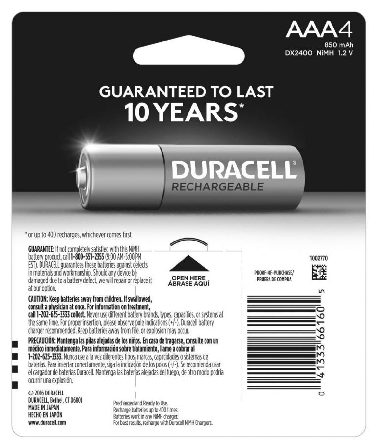
                                        At least one of the advertised cells achieves this through trickery – a DC-DC built in to the cell, the latter appears evidently to be 3.6V chemistry. The DC-DC converts to 1.5V, and also seems to be the 'charger' when charging the cell from 5V ( a USB port, it would appear).

                                        The advertised 1.5V rechargeable DURACELL's – I have failed to find an image of the cell, or a blister pack image of 'cells' actually showing the depicted 1.5V on the cell itself! Also, non of the MANY vendors of this specific cell have any in stock! Phantomware?

                                        Anyway, assuming life is good, and the so called 1.5V rechargeables all use an integral DC-DC, maybe with all the fanfare regarding the caliper's noise sensitivity, the cell won't work anyway – perhaps the DC-DC noise will be an issue?

                                        Regardless, I was just stirring a little – As Michael asked – show me a 1.5v rechargeable cell where the native chemistry results in a direct nominal 1.5v .

                                        Joe

                                        #462966
                                        Michael Gilligan
                                        Participant
                                          @michaelgilligan61133

                                          Well … The Duracells are certainly off my list of candidates

                                          Here’s the back of the package:

                                          532ef38b-cc40-4efd-bab9-fbec7df3f655.jpeg

                                          #462980
                                          Anonymous

                                            SoD: Ok as far as it goes. thumbs up But I'd expect the problem to be due to noise direct from the DC-DC converter, not external pickup.

                                            Andrew

                                            #462981
                                            Joseph Noci 1
                                            Participant
                                              @josephnoci1

                                              That 'advertising' for you! Blatantly stating 1.5V but not letting one see the truth…!

                                              Joe

                                              #462995
                                              Michael Gilligan
                                              Participant
                                                @michaelgilligan61133

                                                Hidden in plain sight, Joe

                                                The photo is grabbed from the link that you provided.

                                                MichaelG.

                                                #463001
                                                Macolm
                                                Participant
                                                  @macolm

                                                  Presumably the integrated circuit in a digital calliper uses the same type of CMOS as watches. Here, in the interests of best battery life, the FET device parameters are chosen to minimise the totem-pole currents (as well as otherwise operating reliably). The absence of external connection, and the fairly complete Faraday cage of the case means that watches are generally immune to ordinary levels of interference.

                                                  The same technology is not so sensible for digital callipers, particularly when an external connection is able to import RFI. It occurs that a possible investigation might be to increase the voltage of external supply slightly from 1.5v.

                                                  Initially, the supply current should be graphed against increasing voltage from 1.5v upwards to, say, 2.0v , or until the current indicates chip dissipation of a few milli-watts. For example, at 2.0v, 500 micro amps would result in 1 milli-watt, and hopefully such a small dissipation and over-voltage would do no harm. An increased supply voltage should provide higher noise immunity. Decoupling at the calliper would clearly still be essential.

                                                  Anyone looking for a project?

                                                  #463003
                                                  SillyOldDuffer
                                                  Moderator
                                                    @sillyoldduffer
                                                    Posted by Andrew Johnston on 07/04/2020 14:08:44:

                                                    SoD: Ok as far as it goes. thumbs up But I'd expect the problem to be due to noise direct from the DC-DC converter, not external pickup.

                                                    Andrew

                                                    Method in my madness though! I tested my caliper with a linear PSU and 40cm leads and it was all over the place. Previously, I'd powered the same caliper from an Arduino with short 5cm leads and it was fine. (Arduino's on-board linear regulator, my potential divider.)

                                                    Thinking about it though the experiment isn't convincing. I ought to repeat it with a battery rather than a mains PSU. If I repeat with battery clean volts and the caliper still misbehaves, it must be noise picked up by the wires?

                                                    Induced noise is quite likely I feel because the caliper is high impedance? (I make 6uA at 1.55v about 260kΩ but you know what my maths is like!)

                                                    I still think my conclusions about the caliper being very sensitive to low volts are valid though. I found:

                                                    My caliper fails absolutely below 1.48V and was reliable only above 1.51V. The SR44 cell produces 1.55V, and this voltage appears to be critical : a drop of 0.05V is enough to upset this caliper, at least with my noisy supply.

                                                    No harm in checking again especially as I qualified the conclusion with 'at least with my noisy supply'. Playing electronics is more interesting than tidying, which is what I'm supposed to be doing! I might have a glass of wine and do the experiment in a drunken haze.

                                                    Dave

                                                    Edited By SillyOldDuffer on 07/04/2020 15:45:07

                                                    #463442
                                                    Sparks
                                                    Participant
                                                      @sparks

                                                      How about using screen leads, grounding the outer screens ONLY at the Caliper end? Dunno if a common mode choke will work along with some decoupling caps. these will need be near the input.

                                                      Sounds like there's very little decoupling in the calipers and a high impedance on the supply line to save battery drain….. try and get the external battery to work and then the external power supply.

                                                      Dave

                                                    Viewing 25 posts - 26 through 50 (of 73 total)
                                                    • Please log in to reply to this topic. Registering is free and easy using the links on the menu at the top of this page.

                                                    Advert

                                                    Latest Replies

                                                    Viewing 25 topics - 1 through 25 (of 25 total)
                                                    Viewing 25 topics - 1 through 25 (of 25 total)

                                                    View full reply list.

                                                    Advert

                                                    Newsletter Sign-up