clarke lathe problem.

Advert

clarke lathe problem.

Home Forums Help and Assistance! (Offered or Wanted) clarke lathe problem.

Viewing 11 posts - 1 through 11 (of 11 total)
  • Author
    Posts
  • #33311
    Geoffrey Gould
    Participant
      @geoffreygould68044

      electrical speed control.

      Advert
      #380428
      Geoffrey Gould
      Participant
        @geoffreygould68044

        Hello Creetings, this is my first post so I hope its in the correct place, if not then apologies.

        The lathe is a clarke cl300m, the problem is that the variable speed control only starts to increase the speed after it has been rotated for 1/3 of its travel. The control should be 4.7K ohms but actually measures 4.0K, I would not have thought that this would make 'that' much difference. R17 is slighty discoulred, not burnt, the colours have never been very clear and apear to be browm/black/brown but that is a pure guess.

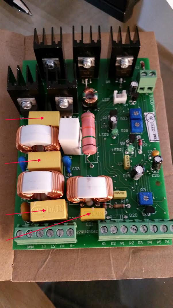
        The PCB is a SEIG XMT 2325.

        Any suggestions would be gratefully received.

        Thank you.

        Geoff Gould.

        #380439
        Tim Stevens
        Participant
          @timstevens64731

          A bit of history on your machine would perhaps help with diagnosis, too. Has it slowly got worse, or was it sudden, and what else was happening at the time? It certainly sounds like a replacement potentiometer is needed, but that is the only detail you have offered so far.

          cheers, Tim

          #380444
          Brian Oldford
          Participant
            @brianoldford70365

            The resistor marking suggest it started life as a nominal 100 ohms. Does it have a tolerance marking?

            It might be worth checking with a meter. If anyone has a similar controller perhaps they could measure theirs and let you know its value.

            #380470
            Les Jones 1
            Participant
              @lesjones1

              From this picture of the XMT2325 I think R17 is the large resistor in the middle of the board.

              xmt2325 1.jpg

              If I am correct it's value is 15 K ohms.

              Les.

              #380480
              John Paton 1
              Participant
                @johnpaton1

                and 5% tolerance (gold band)?

                #380482
                Neil Wyatt
                Moderator
                  @neilwyatt

                  There should be a 'dead' zone after the switch has operated before the motor starts.

                  Have a look at this long thread (especially pages 1 and 7) for the functions of the three small adjustment pots. Check you have the same board.

                  http://www.model-engineer.co.uk/forums/postings.asp?th=38809&p=7

                  Neil

                  Edited By Neil Wyatt on 13/11/2018 21:38:39

                  #380490
                  John Rudd
                  Participant
                    @johnrudd16576

                    As a repairer of many speed control boards, I can confirm that R17 should read as 15k, its power rating should be in excess of 2 watts. The resistor fitted is of carbon film, really needs to be wire wound if longevity is required…they do dissipate some heat….that particular resistor is also responsible for a high failure rate in boards not working/ working properly..

                    I do not recommend "twiddling" any of the pots on board without proper diagnosis…

                    As to the value of the 4.7k pot, how was this measured?


                    Edited By John Rudd on 13/11/2018 22:21:12

                    #380581
                    Geoffrey Gould
                    Participant
                      @geoffreygould68044

                      Good afternoon gentlemen, thank you very much for your many and quick answers, I was very surprised. A little about me, late seventies and eyesight not as sharp as it was, hands a bit shakey and a faulty memory chip!!

                      Anyway here goes.

                      Tim steadilly got worse not a sudden thing.

                      Brian measured at spot on 14K.

                      Les and John you are quite correct at 15K, seems to be what it was, reads 14K spot on, has a gold band but the other colours have not been good as regards being able to be read from new!

                      Neil sorry mine must be a different board because it does not have a switched pot.

                      John measured (4k.) disconected , AVO 8 Mk6. Also measured from wiper end to end and gives a smooth reading with no dead spots.

                      I have split the answers as memory not good enough to retain all the info. at one go.

                      I checked the F & R switch as I had the board to hand and noted that there was a tendensy for one set of contacts to give a reading, when closed ,sometimes, of 400 ohms. I have ordered a new switch.

                      Something I have just remembered is that when the switch is in 'neautral' the motor will run for a second or give a kick a couple of times, in the falword direction. This happens very very ocasionally.

                      Many thanks for your help and interest.

                      Nothing will be twiddled with the small adjustment pots, they are very well sealed and I don't think it is a good idea. There are a lot of smd's on the back of the PCB and the soldering does not look too clever ( lead free solder?) I don't think that either my soldering iron , not hot enough, or indeed I am good enough to tidy things up without doing some damage!!

                      Thank you again.

                      Now for a bit of a laugh just to prove that actually I am a Geneous Ha Ha. Replaced the bearings in the gearbox with a better quality set. Spun the chuck by hand and at one point there wa a rubbing sound, instant panic, what have I done. A cork from a champayne bottle was a perfect fit in the shaft to stop swarf dropping into the gear set. It has a plastic top, if it is pushed in too far it rubs on the gear case. Silly twit.

                      All the best.

                      Geoff.

                      #381190
                      Geoffrey Gould
                      Participant
                        @geoffreygould68044

                        Hello everybody, first an apology sorry but I got it wrong with the 240 volt reference with the switch contacts being burnt, it was the Motor supply contacts, got my wires crossed (in my head, not physically!).

                        I am very pleased the pot arrived yesterday and measured just a few ohms short of 4.7K. The combination of R17 and the pot has made it into a different machine, instead of being sudden and course the control now starts to operate after about 3/16” of turn. I can control the speed smoothly from just turning, I haven’t timed it but something like 8 seconds to turn 360 degrees. It is completely smooth with no fluctuation which is something it would not do before as it tended to ‘hunt’.

                        The new gearbox bearings are so much better, smooth with absolutely no play what so ever, I put a 6mm bar in the chuck and was able to set it up with less than .001” run out, the bar surface was a bit rough, oh the wonders of a 4 jaw chuck, I should have done this long ago.

                        I was able to true up the bar and take .0005” cuts and have a lovely finish. Before that would not have been possible at all, the surface would have been rough and uneven.

                        Ordered some good turning tools and a light so I might stand a better chance of seeing what I am doing.

                        Your help and encouragement have been great, having started from scratch it is a learning process. Space is very limited so something bigger is out I am afraid.

                        Will be back I suspect with more questions I think.

                        All the best.

                        Geoff.

                        Actually, forgot to ask are there any uprated SCR’s? etc. and a wiring diagram so I may understand the workings better, got a curious mind!

                        #381191
                        Geoffrey Gould
                        Participant
                          @geoffreygould68044

                          Hi sorry it apears that something I posted has disapeared, probably not that important, a bit of a waffle so please ignore the remarks about 240 Volts, the switch contacts burned still stands, it was the motor supply.

                          Cheers.

                          Geoff.

                        Viewing 11 posts - 1 through 11 (of 11 total)
                        • Please log in to reply to this topic. Registering is free and easy using the links on the menu at the top of this page.

                        Advert

                        Latest Replies

                        Viewing 25 topics - 1 through 25 (of 25 total)
                        Viewing 25 topics - 1 through 25 (of 25 total)

                        View full reply list.

                        Advert

                        Newsletter Sign-up