Batch turning small parts to tolerance

Advert

Batch turning small parts to tolerance

Home Forums Beginners questions Batch turning small parts to tolerance

Viewing 18 posts - 1 through 18 (of 18 total)
  • Author
    Posts
  • #392451
    Robin Graham
    Participant
      @robingraham42208

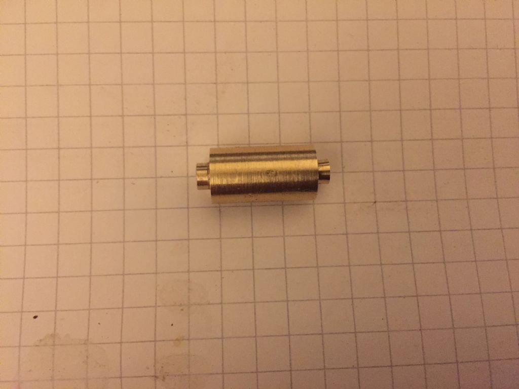
      I want to make a small batch (maybe 12) of rollers like this:


      img_1906.jpg


      I would like to get the width of the rollers between shoulders to 15mm +0 / -0.05mm – the prototype in the pic is actually within that tolerance despite appearances – either cr@ppy graph paper or a trick of the camera!

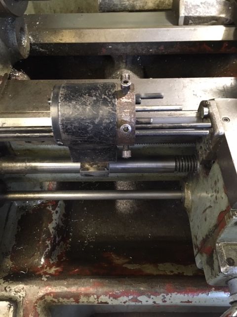
      How would folk go about it? I have a carriage stop which is good to better than +/- 0.01 mm (according to the lathe DRO) and also a backstop which I made a some time ago:

      dsc_0501.jpg


      I fouled up on the design – the first and only time I used it the MT got well stuck in the lathe spindle and it was the devil of a job to get it out – I hadn't made any provision for extraction. I could ( should) re-machine it to correct that, but I'm not convinced it would work for this job. The chuck jaws are 50mm deep so I'd have to make a longish slender extension to the stop. Is it likely that I could hold the tolerance I want with this arrangement if I sort out the design of the backstop? Or is there a better way to do this?

      Robin.


      Edited By Robin Graham on 22/01/2019 23:10:50

      Edited By Robin Graham on 22/01/2019 23:22:50

      Advert
      #9491
      Robin Graham
      Participant
        @robingraham42208
        #392457
        Emgee
        Participant
          @emgee

          You don't say which material but you could perhaps use a grooving tool for all operations, lengths can be read direct off the DRO as can the diameters if the DRO is set to show diameter.
          You need length of workpiece plus a parting allowance and chuck to tool clearance extending from the jaws to start with.

          Emgee

          #392458
          John Reese
          Participant
            @johnreese12848

            A draw type collet with a stop will not work. If the stock diameter varies the collet position, when closed, will vary.

            I would use a backstop n the spindle. The work would be held in a 3-jaw chuck. I would saw the blanks to approximate length. Face, machine shoulder, drill & tap one end. Do all pieces. Do the same to the other end.

            How the lathe carriage stop is used is key. I have a 4 position carriage stop so I can set up all 4 stop positions in advance using a test part.

            If using a fixed stop, make a spacer equal in thickness to the length of the spigot. Hold the spacer against the fixed stop when facing off. The stop without the spacer will control the length of the spigot. Reset he fixed stop to get the correct shoulder to shoulder length. Do the second end of the part in the same manner as the first.

            For more consistent results a tubular backstop contacting only the shoulder could be used

            #392460
            Neil Lickfold
            Participant
              @neillickfold44316

              It looks to me , that part can all be made using a MDT , multi direction Turning tool. Looks like a parting off blade, but has side clearance to be able to takes cuts left and right. If both ends are the same diameter, you can plunge cut the outer end, then go in to the 1st shoulder length and cut to finish diameter and traverse out. Skim the od, then plunge cut the back shoulder, and the remainder of the back material, then part off.

              Without knowing the stock you have and material etc. But with the above approach is quite easy on a Myford, If you have decent digit read out, it will be even easier.

              Keep in mind, that with most digital readouts, you need to be still going in the same direction every time to get really good results. A bit like taking away the backlash on a lathe nut.

              Neil

              #392462
              Jeff Dayman
              Participant
                @jeffdayman43397

                12 pcs may not justify the method below, but for lg qty here's how I would do it on a home shop lathe. The method assumes you have a 4 or 6 position QC toolholder.

                1. Make a two tool cutter with the HSS cutters mounted in a block 15 mm (plus or minus X within your tolerance) apart, and wide enough to cut the end dia's plus partoff tool width at headstock end.

                2. set up above two tool cutter in toolholder, and set up a parting tool for next indexed op.

                3. set up a work stop on the tailstock (could be just a rod in the drill chuck, and a removeable spacer so the stock doesn't rub on the stop) and arrange stock to feed through spindle hole up to spacer on stop. The stop and spacer should be set relative to the two tool cutter so cut is in correct place relative to stock end. Lock tailstock.

                after setting up as above, ops as follows:

                1. feed stock through spindle, through chuck or collet , to the spacer on the stop rod. Tighten chuck or collet.

                2. remove spacer from stop rod.

                3. make cuts to depth on ends with the two tool cutter, using cross slide (carriage locked).

                4. index toolholder to the parting tool, to part off cleanly (no pip ideally)

                5. replace spacer on stop rod. Index toolholder back to two tool cutter

                6. repeat for next part.

                Just my $0.02 worth. Done many like it. Standing by for the flaming. Just trying to offer simple practical methods.

                Edited By Jeff Dayman on 23/01/2019 00:53:35

                #392463
                John Reese
                Participant
                  @johnreese12848

                  The ideal tool would be a CCMT or similar shaped HSS. The same tool could be used for both facing and turning. If an a sharp interior corner were requires the tool would hae to be HSS.

                  #392466
                  John McNamara
                  Participant
                    @johnmcnamara74883

                    A backstop in the spindle is very useful to turn parts to dead length, easy to make at minimal cost. Mine is just a piece of threaded rod with its end bored and carefully faced, the bored hole means that any pip or slight bulge in the part face will not change the length. Just remember its there if you are working with a small diameter part that would fall into the hole.

                    On bigger lathes you may need a version for long and a version for short parts to avoid too much stick out of the threaded rod from the headstock, not safe and it can vibrate.

                    You will need to make some sort of split expanding collet to hold the stop securely in the spindle bore not hard to make it does not have to be super accurate. keep it short so that you have more capacity to hold longer parts.

                    Depending on the length of the spindle bore you may need to support the free end of the threaded rod in the bore, On my setup I did and made one from a piece of nylon cutting board a running not tight fit in the bore mounted between nuts and washers on the threaded rod, it does not rattle and keeps the rod centered.

                    Regards
                    John

                    Edited By John McNamara on 23/01/2019 01:20:48

                    #392467
                    Hopper
                    Participant
                      @hopper

                      12 parts is not worth setting up a production run for. Just make them in the normal manner.

                      #392472
                      Chris Trice
                      Participant
                        @christrice43267

                        As others have mentioned, you'll find a spindle backstop invaluable for repetitive work. Combined with a DRO, you can machine parts consistently accurately.

                        #392474
                        Neil Lickfold
                        Participant
                          @neillickfold44316

                          When I was making a series of parts with a thread and a 45 deg taper that was a fit to another part, I made a series of tool stops. So I faced the end of the bar, then tuned the Ø6mm length based on the tool stop that touched the end of the part. Then when the diameter stepped up to 9mm , the length was on the step of the tool stop,and again touched the end of the work piece. The final diameter of 13mm and and allowance for parting off, was the last step in the stop bar. So it is progressed a bit like a wood workers tool. The taper turn tool had some of the material removed already, and again had its own tool stop that referenced off the end face of the part.

                          It worked really well, and is only as good as the stop is set / made. The down side is if the radial distance is too close, it becomes not a very practical of an option.

                          The Parting tool used a stop as well. When the part was at about 3mm to go, the stop had worked its way off the diameter of the end detail, so it was free to fall and not jam up on the parting tool. My lathe does not have DRO. From batch to batch, these parts were quite accurate. As long as there was no swarf on the end face etc, and no pip at the centre. I normally where ever possible, leave a centre drill spot on the end faces. That way the tools never have to turn to zero when facing, Makes all your tools so much longer , on harder materials for sure.

                          #392492
                          Neil Wyatt
                          Moderator
                            @neilwyatt
                            • Make a batch of parts but only one with the final shoulder not cut.
                            • Make a cylinder with a flange, the cylinder a bit wider than the parts.
                            • Centre pop to mark the flange for jaw 1 and chuck in 3-jaw.
                            • Drill slightly larger than the spigot.
                            • Drill and finish with d-bit to make a flat-bottomed hole to suit the body of the parts.
                            • Remove, cut three slits and replace.
                            • Use as a collet to hold the finished example to set a tool and stop for cutting the shoulders.
                            • Now work through the unfinished parts and make the shoulders.

                            Not really worth the bother for 12 which are more easily done with a parting tool, and using the top slide to move it by the width across the flange + tool width.

                            Neil

                            #392494
                            Martin Kyte
                            Participant
                              @martinkyte99762

                              Or if you don't want to bother with the backstop in the taper then:-

                              Make all the blanks and centre drill one end.

                              Finish the shoulder on the other end.

                              Rough turn the shoulder on the second end

                              Hold the part in the 3 jaw by the spigot so that the shoulder is against the chuck jaws and with the other end supported by a tailstock centre.

                              Finish turn the shoulders to the correct length with the saddle locked and they will all be identical.

                              regards Martin

                              (Works a treat for clock pillars)

                              #392605
                              jimmy b
                              Participant
                                @jimmyb

                                I'd just bore some soft jaws.

                                Jim

                                #393154
                                Robin Graham
                                Participant
                                  @robingraham42208

                                  Thanks for suggestions – I've been a bit deprived of workshop time lately so haven't implemented any yet, but shall do.

                                  I understand that for such a small batch the most efficient way might be to 'do it conventionally', but being a self-teacher I sometimes do things the hard way just to develop skills and increase knowledge.

                                  Robin

                                  #393160
                                  Martin Connelly
                                  Participant
                                    @martinconnelly55370

                                    My version of a spindle backstop as mentioned above is to put a rod or tube in a collet then fit a chuck over it.

                                    Martin C

                                    #393166
                                    JasonB
                                    Moderator
                                      @jasonb

                                      As you have a DRO you can use that as your "stop" to position the work.

                                      1. Mount up a parting tool and zero the DRO when it is overall length plus say 2mm from the chuck jaws.

                                      2. Put bar into chuck and hold the end against the edge of the parting tool as you tighten the chuck.

                                      3. Now move carrage until DRO reads overall length and part off.

                                      4. Return carrage to zero and set the next piece of work.

                                      5. Go back to No2.

                                      For the spigots do similar

                                      1. Mount a tool that will cut and face such as CCMT and zero DRO at spigot length plus 2mm from chuck.

                                      2. Put work into chick and set length against tool

                                      3 Cut spigot using DRO for length and zero depth once first spigot is to diameter

                                      4. Back to No2 for the next one but use the zero depth for the rest.

                                      #393212
                                      Clive Foster
                                      Participant
                                        @clivefoster55965

                                        This is the sort of job the multi-position bed stop was invented for. Especially useful if you have a QC tool-post and longitudinal travel dial on the apron or, better, a DRO.

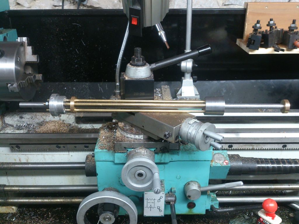
                                        Here is mine :-

                                        multi position bed stop.jpg

                                        I use the apron dial to set the stop positions for workpiece extension from the chuck or collet for both turning operations and parting off as I don't have a DRO on the lathe. Big advantage is being able to do the whole job in sequence on the parent bar before parting off. I'd use a collet for that job as my spindle is native 5C and I have a full set of collets to fit.

                                        I use the Morse Taper drill carrying block out of my Dickson QC to set-up initial workpiece extension. Side is flat to close limits so it makes a nice solid work-stop. As I have the device might as well use it for something! (Also use it for setting the tool-post square to the tailstock barrel. Yet to meet any Home Shop person who actually uses one for its intended purpose tho'.)

                                        With this sort of step turned job I find it worthwhile to take the time to adjust tool projections so that the final cuts are made with the cross slide dial reading zero. Easier with a decent DRO as they all seem to be able to store multiple zero positions. Assuming you have the discipline to switch zero position number when changing tools.

                                        Habitually setting up to finish on dial zero is an effective way of limiting the number of "Oh bother. Took off too much!" moments.

                                        Frankly setting the stop up is about the tipping point as to whether a DRO is worth having (I have dual imperial / metric dials). I imagine that with a DRO set-up is so fast that using the stop would pretty much be the normal way of doing anything more than a couple of parts.

                                        Clive


                                        Edited By Clive Foster on 27/01/2019 12:02:48

                                        Edited By Clive Foster on 27/01/2019 12:35:20

                                      Viewing 18 posts - 1 through 18 (of 18 total)
                                      • Please log in to reply to this topic. Registering is free and easy using the links on the menu at the top of this page.

                                      Advert

                                      Latest Replies

                                      Home Forums Beginners questions Topics

                                      Viewing 25 topics - 1 through 25 (of 25 total)
                                      Viewing 25 topics - 1 through 25 (of 25 total)

                                      View full reply list.

                                      Advert

                                      Newsletter Sign-up