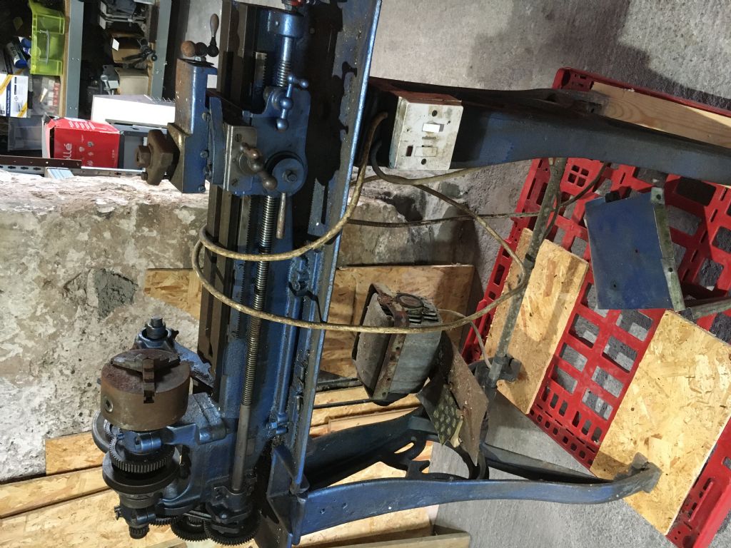
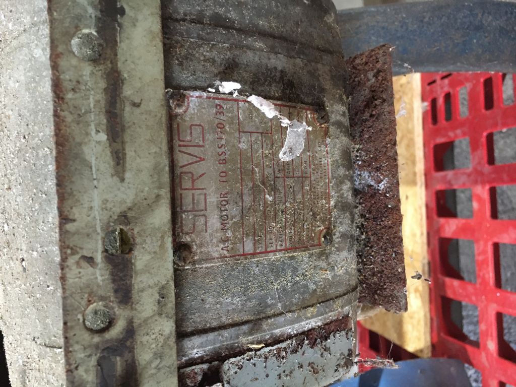
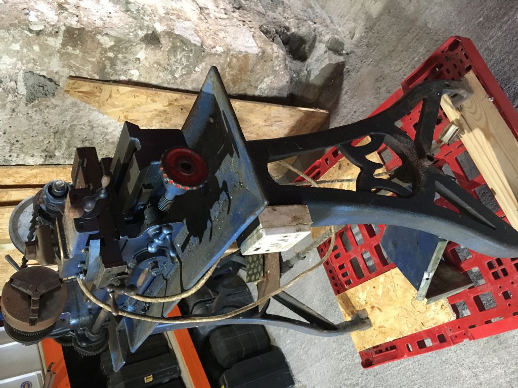
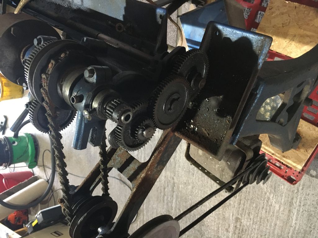
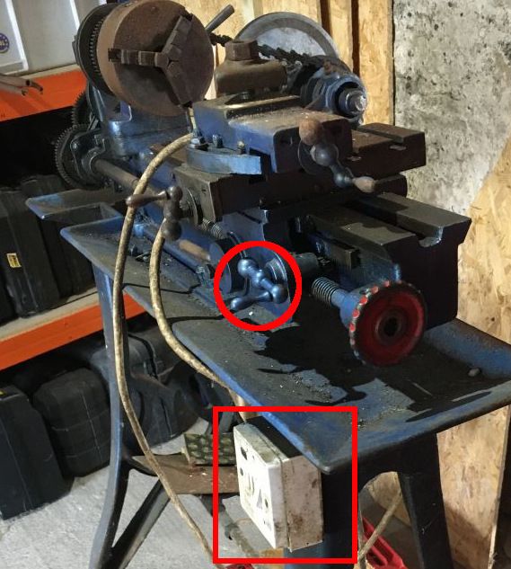
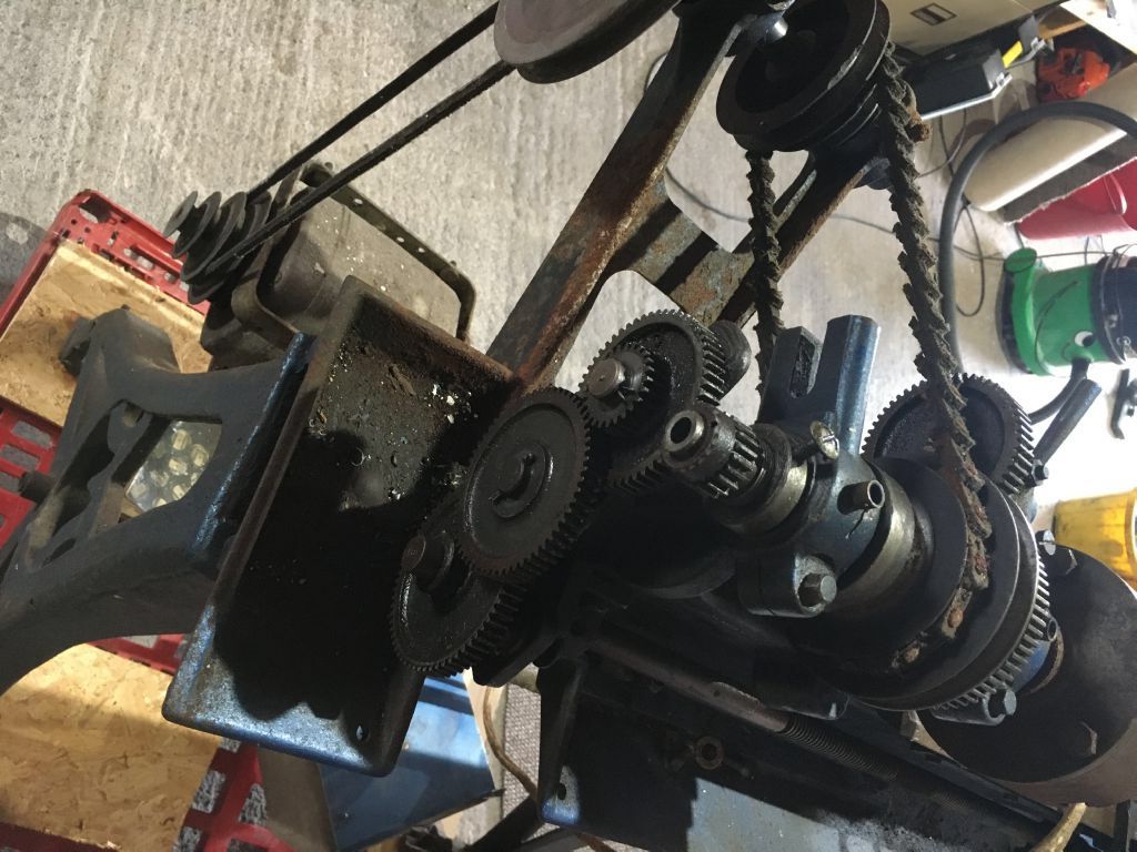
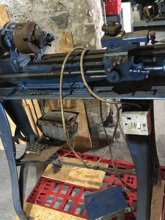
Can't see clearly enough for my old eyes, but it does look like a Myford ML
Yes, it needs a Tailstock.
It can be quite a useable little machine.
If it needs to be said, Do NOT engage back gear to remove the chuck. This is likely to result in broken teeth on the gears.
Not all machines had Tumbler Reverse; that was an optional extra for a new machine.
When back gear is engaged, the grubscrew in the bottom of the vee in the Headstock cone pulley needs to be slackened off. (Preferably removed, and put in a safe place, so that it cannot fly out and get lost when the lathe is running ).
There is a lot of information on the Lathes UK website (which is where a lot of what follows comes from )
If you need telling, the threads will be BSF and BSW, possibly BA for the gibs.
If it is a long bed (24" centres or so, it will be a ML2 or ML4. ML1 and ML 3 were 15" centres )
You will already have found that the Saddle Handwheel moves in the opposite way to what you may expect; i.e. clockwise rotation moves the Saddle away from the Headstock.
The ML1 and ML2 had a centre height of 3.125". The ML3 and 4 were 3.5" centre height
Very early MLs had the Headstock cast into the bed. On later ones the headstock was secured to the bed with 1/4 BSF studs and nuts. production started in about 1937, and ended in the 1940s. These machines were superceded by the ML7 which was introduced in 1947.
The early Mandrels had a standard 3/4 BSW 9 tpi thread, this was superceded by a 3/4 x 12 tpi thread, and i think that the very latest had the 1.125 x 12 tpi thread used on the Series 7 machines.
For my friend, I made up a 3/4 BSW to 1.125 x 12 tpi adaptor, so that the later Myford standard backplates and chucks could be fitted.
There should be a cover over the changewheels. A few machines had a cover with a vertical hinge, but most, I believe, hinged about a horizontal shaft (carried in a cast bracket ) secured behind the Headstock, with 5/16 setscrews..
Having the bracket, but not the cover, I made one from some sheet Aluminium, pop rivets, some simple collars, and some 5/32 Whitworth setscrews. One setscrew was modified to fit the slot in the bracket, which limits the travel of the cover.
Change wheels should run from 20T to 65T in increments of 5T. There should be two 20T, but only one 60T. in the complete set.
The gears are driven and compounded, by 3/32" pins connecting the gears to each other or the driving collars, (on Mandrel and Leadscrew ).
If you are short of Changewheels, 7 Series wheels will fit, but will need to be drilled part way through to take the 3/32" driving pin. Drill the hole away from the keyway! The gears are 20 DP, 14.5 pressure angle.
The leadscrew is 8 tpi.
If you can collect three x 20T gears, two x 60T gears and a 65T you can set up a 20 : 60/20 : 65/20 : 60 train which will provide a fine feed of 0.00427" / rev.. You may need to fettle the inside of the ends of the banjo to fit in all three studs to set up the geartrain.
The Cross Slide and Top Slide Leadscrews are 12 tpi, and the dials have 80 divisions, so each division is not 0.001", but, 0.00104".
With a full set of changewheels, you would be able to cut a range of Imperial screw threads
Headstock and Tailstock are both 1 MT.
If you lack centres (ideally you need at least two, preferably three ), they can be made by cutting the flutes off (preferably scrap ) 1 MT drills, and offsetting the Top Slide by 30 degrees to produce the 60 degree centre.
It will be worth spending time making a Centre Height Gauge. It will make setting tools, so much easier!
Hope that this is helpful, but not insulting to your intelligence.
Howard
SillyOldDuffer.


