Alexander master toolmaker

Advert

Alexander master toolmaker

Home Forums Manual machine tools Alexander master toolmaker

Viewing 21 posts - 51 through 71 (of 71 total)
  • Author
    Posts
  • #444043
    David Broadbent
    Participant
      @davidbroadbent33226

      img_4183.jpg

      Advert
      #444044
      Brian H
      Participant
        @brianh50089

        David, I can let you have 2 or 3 pins at 3,94 at the large end by 32,46 long if they are any use. If so just PM me with your address.

        Brian

        Or, a search on Ebay has possibilities


        Edited By Brian H on 31/12/2019 14:28:03

        #444062
        mark smith 20
        Participant
          @marksmith20
          Posted by David Broadbent on 30/12/2019 13:00:27:

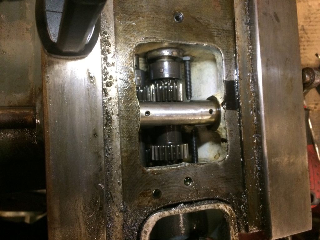
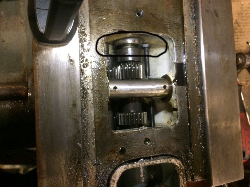
          I think this is the most telling shot – the 4mm gap above the upper dog clutch.

          img_4172.jpg

          Where is this 4mm gap your refering to?

          #444085
          David Broadbent
          Participant
            @davidbroadbent33226

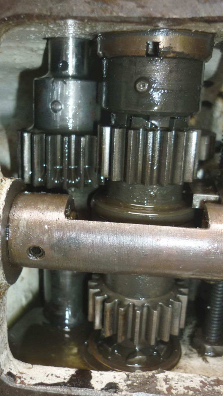
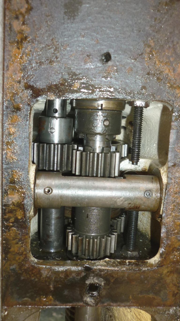
            Take a look at the photo, the 4mm gap is between the top of the dog clutch and the bearing tube as it emerges from the casting. You can also see on this photo that the selector quadrant is against its lower stop although the upper dog clutch is fully engaged.

            As I discovered this was due to the lower bevel drive being rusted solid to the drive shaft lower down. As the machine tried to move the table upwards under power, the rusted bevel drive didn't allow the shaft to move, so the carriage moved without it – effectively pulling the shaft downwards, shearing the taper pin in the upper bevel drive and creating the 4mm gap you see. I hope that's clear – it isn't easy to desc ribe in so few words!

            #444089
            Phil P
            Participant
              @philp

              Does this help ?

              847555.jpg

              #444119
              mark smith 20
              Participant
                @marksmith20

                Thanks , does mine look right??

                p1290393.jpg

                p1290335.jpg

                #444242
                David Broadbent
                Participant
                  @davidbroadbent33226

                  In my limited, recent experience I would say yours looks fine. The 4mm gap I saw was the distance that the carriage had been pulled off the shaft, shearing the taper pin in the upper bevel gear in the process. There can't have been much shaft still within the bevel gear actually, although it still worked as the mechanism was turned by hand. The gap was the only indication that anything was actually wrong.

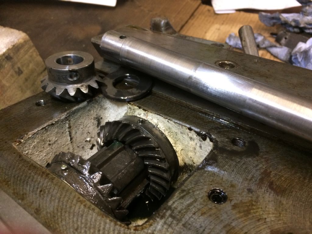
                  Normally the distance between the upper dog clutch and the upper bevel gear is fixed by both parts being located on the shaft by taper pins. In fact that is the only vertical location provided for the shaft, everything else being keyed to slide up and down it. There is a thick washer under the upper bevel gear, which may possibly be some kind of selective assembly fit as there are no other shims or packers in the system to eliminate any up and down movement. My guess would be that the thick washer maintains the optimum clearance between the upper bevel gear and the upper dog clutch to the bearing tube that sits between those two parts and sits slightly proud of the casting as it emerges top and bottom. The correct setting of the upper bevel gear into the two crown wheels within which it runs is then achieved by moving this bearing tube within the machine casting. Once set this tube is fixed in place by a pair of grub screws. The diagram posted by Phil P illustrates this relationship pretty well – although it only shows one grub screw holding what may even be a two part bearing tube in the Deckel machine whereas my machine has an upper and lower grub screw. .

                  To me it looks like the whole thing is designed to run for a long time without being messed about with – unless of course the machine is left outside for several years and bits get stuck together with rust causing a taper pin to shear!

                  #444289
                  Bikepete
                  Participant
                    @bikepete
                    Posted by David Broadbent on 31/12/2019 13:58:42:

                    …The Deckel handbook identifies the pin as a "4 x 30 Din 1" which would probably not be far away but would be a different taper than an Imperial pin? Measuring the holes in the bevel gear seems to suggest 11/64" x 1 1/8" as the nearest fractional imperial size, so it looks like a job for the old Raglan – unless anyone knows where such a thing might be bought in quantities of less than 100?

                    You can buy just a single one here:

                    https://www.ebay.co.uk/itm/Qualfast-4x30mm-Taper-Pin-Turned/143060355755

                    and FWIW that listing helpfully also includes a note that "Standard inch-sized taper pins have a taper on diameter of 1:48 while metric ones have a taper of 1:50".


                    Edited By Bikepete on 02/01/2020 11:42:34

                    #444301
                    Phil P
                    Participant
                      @philp
                      You can buy just a single one here:

                      **LINK**

                      Pete

                      That listing is actually for a box of 50.

                      David

                      I will have a look in my box of taper pins tonight and see if have an odd one spare.

                      Phil

                      #444309
                      Bikepete
                      Participant
                        @bikepete
                        Posted by Phil P on 02/01/2020 12:55:46:

                        That listing is actually for a box of 50.

                        Doh! Well spotted Phil. Did seem like the price was 'ambitious' for just one…

                        Great to see this proceeding towards a successful conclusion – as a former owner of a very similar Deckel it is good to see it being given a new lease of life. Good work David and hope it serves you well once repaired.

                        #444339
                        Brian H
                        Participant
                          @brianh50089

                          David, I put some pins in the post for you this morning (02-01-2020).

                          Brian

                          #444452
                          David Broadbent
                          Participant
                            @davidbroadbent33226

                            Just received your taper pins in this morning's post, Brian and rushed out to try them. Sadly they are too small. If you would like to message me your address I would be happy to return them.

                            The actual measurements I have taken this morning from the hole through the bevel gear show the smaller hole to be 0.152" diam. and the bigger to be 0.166" diam. The pin is just over an inch long. I will have a go at making one today.

                            Currently busy with washing parts in paraffin – although still resisting the temptation to get a tin of paint out!

                            #444505
                            Brian H
                            Participant
                              @brianh50089

                              Sorry they didn't work David. No need to return them, just add them to your spare fasteners box. Please let us know how a bespoke one works out.

                              Brian

                              #444704
                              John Reese
                              Participant
                                @johnreese12848
                                Posted by David Colwill on 22/12/2019 07:48:37:

                                On some tapered gib arrangements there is a screw on each end of the gib. These are used to keep the gib from moving once set. If it isn't properly held it can act as a wedge and I would suspect that this is what is happening on your machine. Try to find out how the gib is secured and back it off. If that frees it of readjust and try to look for movement of the gib when moving the slide.

                                Regards.

                                David.

                                If the gib had only one screw it was common practice to have a slot in the head of the gib that surrounded the head of the screw. That prevented the gib from moving inward and locking the slide. It id possible the head of the gib was broken, losing the slot.

                                #444722
                                Clive Foster
                                Participant
                                  @clivefoster55965

                                  Further to Johns comment about single screw adjusters for taper gibs its important that the screw head is a nice fit in the slot and that the head is exactly perpendicular to the slot. The head is usually quite large in relation to the thread so they can be bent by careless and hamfisted folk.

                                  Moving OT for a moment.

                                  Had the jackpot on a Chinee import mill pushing 20 years ago. Slot too wide, screw shank bent and threaded hole in the slide out of line. An object lesson in how an insecure taper gib can turn into an evil minded self adjusting wedge. I imagine the minimum wage guy on the assembly bench did what he had to to to get it all together despite the misaligned thread. Once I'd identified the problem and re-made the necessary parts it worked very well indeed. A good machine spoilt by a seemingly trivial error.

                                  Clive

                                  #444737
                                  David Broadbent
                                  Participant
                                    @davidbroadbent33226

                                    The gib strips on the Alexander are exactly as you describe with a single screw at one end to tighten the job. I have actually discovered that one had sheared off – no doubt due to over enthusiastic tightening at some point. Somebody had introduced a metal plate, held to the machine by drilling and tapping for a couple of small bolts. This plate engaged the slot in the gib strip and presumably worked by removing packers from under the plate! I have since managed to extricate the snapped screw and am currently in the process of making a new one for the reassembly. Luckily I have one to copy off.

                                    Dave

                                    #446592
                                    David Broadbent
                                    Participant
                                      @davidbroadbent33226

                                      img_4221.jpgIt has taken longer than I expected, but today I am very pleased to announce that my Alexander milling machine is back up and running with everything functioning perfectly! Thanks again to all who helped in providing invaluable advice.

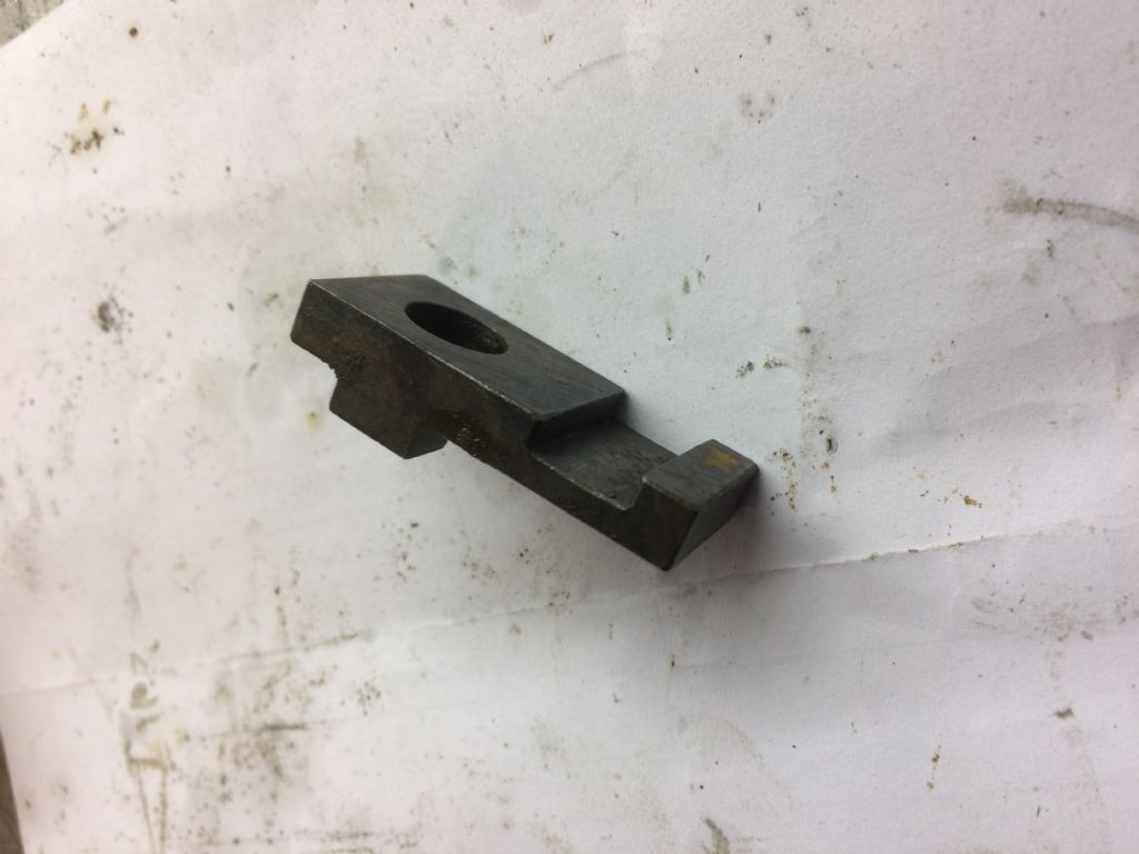
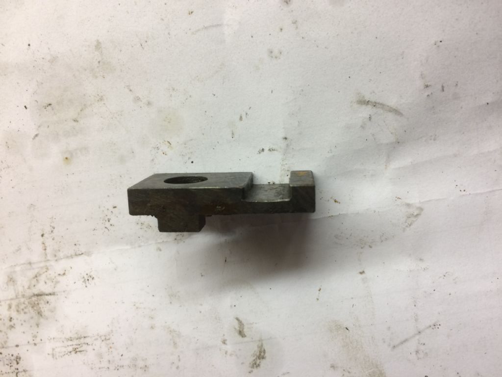
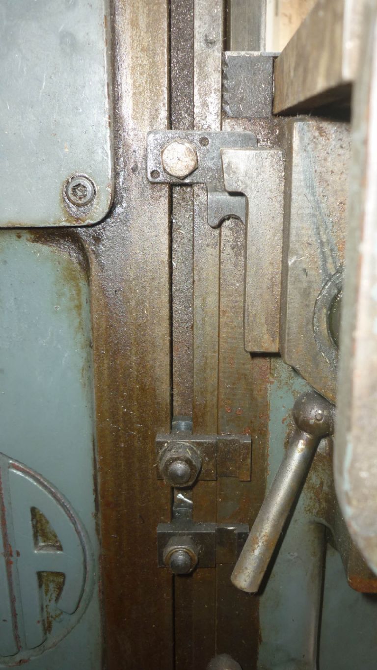
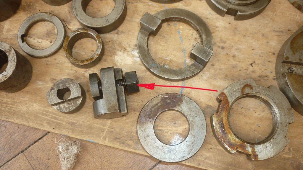
                                      OK so it's up and running but I do have a couple of parts left over! Before I get mercilesslty trolled for this remark can I point out I know where these bits go – just don'timg_4220.jpg know what they do. As you may gather from the pics they fit in the vertical slot you might expect limit stops to fit, but with the channel machined into them – the wheel on the power feed limit crank just passes through/over them. Can anybody tell me how these things are intended to be used – I have three of them!

                                      Thanks again,

                                      Dave

                                      #446609
                                      mark smith 20
                                      Participant
                                        @marksmith20

                                        Dave, they are movable limit trips ,but im also confused how they work. smiley There should be two on each axis in between the fixed ones at the ends.

                                        Heres  mine on the z axis. I also have this bit which im unsure what its for?


                                        Edited By mark smith 20 on 14/01/2020 19:09:25

                                        p1290135.jpg

                                        p1280911.jpg

                                        Edited By mark smith 20 on 14/01/2020 19:16:23

                                        #446611
                                        Phil P
                                        Participant
                                          @philp

                                          When the power feed is already in neutral the trip lever will pass through the slot to prevent you manually crashing into it with the hand wheel feed.

                                          When the power feed is engaged the trip lever will not pass through the slot until it has been pushed into neutral again.

                                          Phil

                                          #446616
                                          Howard Lewis
                                          Participant
                                            @howardlewis46836

                                            Excellent news, David!

                                            Your perseverance has paid off, and now the machine is better than it has been for a very long time!

                                            Good Luck, and Enjoy!

                                            Howard

                                            #482197
                                            Jerry Bland 1
                                            Participant
                                              @jerrybland1

                                              I an so grateful for the information and help in this thread. I am currently stripping and overhauling my 'Master Toolmaker,…. Can anyone help, with where to obtain the felt seals in the housing around the long drive gear ? Regards to all

                                            Viewing 21 posts - 51 through 71 (of 71 total)
                                            • Please log in to reply to this topic. Registering is free and easy using the links on the menu at the top of this page.

                                            Advert

                                            Latest Replies

                                            Home Forums Manual machine tools Topics

                                            Viewing 25 topics - 1 through 25 (of 25 total)
                                            Viewing 25 topics - 1 through 25 (of 25 total)

                                            View full reply list.

                                            Advert

                                            Newsletter Sign-up